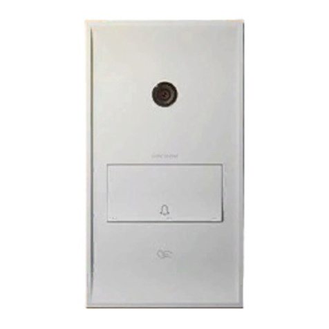
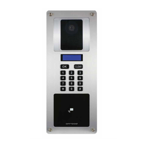
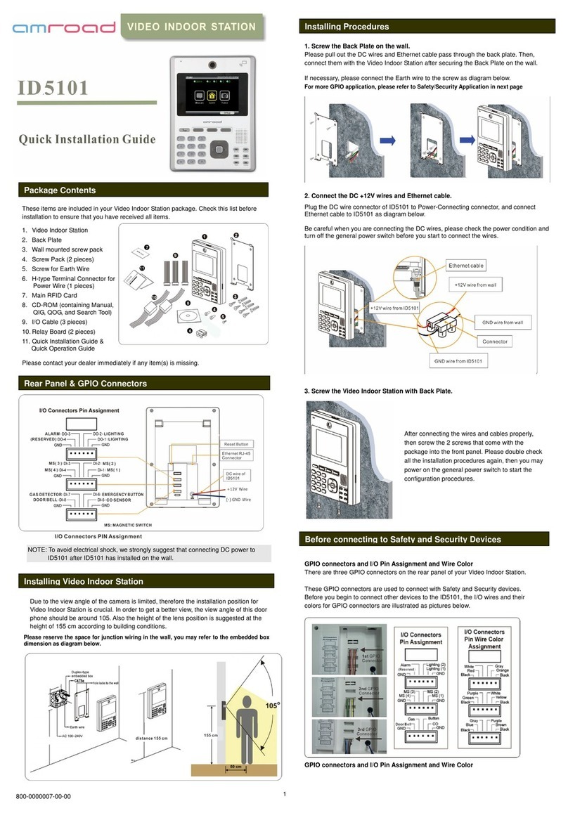
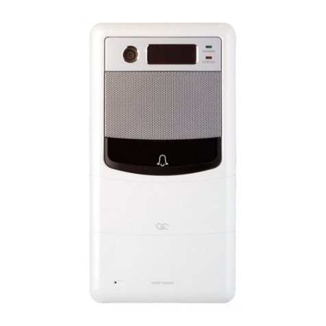
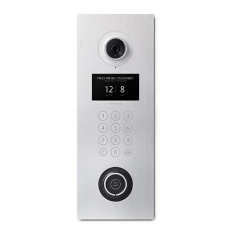
Amroad DB3100R User manual


Copyright
© 2012 Amroad Technology Inc.
All Rights Reserved. No part of this publication may be reproduced, transmitted, transcribed, stored in a retrieval system or translated into any language in any
form or by any means without the express written permission of Amroad Technology Inc. To obtain consent, write to the attention of Amroad Technology Inc.
Document No. DB3100R 2012-0402
www.amroad.com.tw
DISCLAIMER
Amroad reserves the right to change product specification without prior notice.
Changes may be made to the information in this publication without obligation to notify. Amroad shall not be liable for technical or editorial errors contained
herein.
TRADE MARKS
Amroad logo is copyright of Amroad Technology Inc. All other products, services or trade marks mentioned in this document are the property of their respective
owners, companies or organizations.

Contents
Copyright
Chapter 1: Introduction 1
Welcome 1
General Application of Door Entry System 2
Unit in Luxury Apartment Building 2
Use of SIP 3
Chapter 2 : Knowing Video Door Phone 5
Package Contents 5
Front Panel 6
Rear Panel & Side View 7
Dimensions 8
Chapter 3 : Installing Video Door Phone 9
Suggested Installation Position 9
View Angle 9
Installion Procedures 10
1. Prepare Flush-Mounted Box 10
2. Secure Flush-Mounted Box on Steel Frame 11
3. Wire and Cable Connection 12
4. Installing DB3100R Unit 13
Reset Button 14
Connecting to Ground Wire 15

Chapter 4 : Use of the Video Door Phone 17
Making Calls From Video Door Phone 17
Answering Calls on IP Video Phone 17
Open the Door 17
Common Controls 17
DB3100R RFID Card Usage 18
Issue Master RFID Card First Time 18
Issue a New Card with Master RFID Card: 18
Wall Lamp and RFID LED Indicators 19
Status LED 20
Audio Announcement 21
Chapter 5 : Configuring Video Door Phone 23
Finding Video Door Phone on Networks 23
Entering Web User Interface 24
System - Basic Settings 25
System - Networking Settings 26
System Login Name 27
System Reboot 27
Streaming Settings – Video 28
Streaming Settings – Audio 30
SIP Settings 31
Entrance Settings – Extensions 33
Entrance Settings – GPIO 36
Entrance Settings –RFID 38

Upgrade –Upgrade 40
Upgrade –Configuration 41
AR APS 42
Functions Performed by the IP-PBX (Compatible with Amroad IP-PBX) 43
Appendix A : IO Application 45
Electronic Lock 45
Wiring Connection and Web Page Setup 45
Electronic Bolt 45
Electronic Strike 47
Appendix B : Regulatory Information 49
FCC STATEMENT 49
FCC Radiation Exposure Statement 49
CE DECLARATION OF CONFORMITY (EUROPE) 50

Amroad Technology Inc.
1
MANUAL FOR SYSTEM INTEGRATOR
Chapter 1: Introduction
Welcome
Thank you for choosing this Video Door Phone. This device is designed to work as Video Door Phone of inside large building to form a
SIP-based door entry system. Besides taking advantages of IP technologies, this device links to other SIP devices. It will work with most IP
PBX systems supporting audio and video, and it can be configured via a web interface.
This product contains following main features:
• Talk to visitors with real time video and voice on IP Video Phone or Video Indoor Station
• SIP 2.0 (RFC3261) Compliant
• Support H.263 video format.
• Support G.711 audio formats.
• RFID card reader (ISO14443A/13.56MHz (MIFARE Standard) with embedded RFID card database
• Support Peer-to-Peer Mode
• Build-in wide angle lens
•Wall Lamp (White LEDs)
• Build-in speaker and microphone.
• Scan RFID card to open the door
• Support PoE (Power over Ethernet, 802.3af) module (External power supply AC 48V In)
• Web user interface for configuration and management.
Please read this user guide before installing the device. Please contact your dealers or system integrators if you have questions.
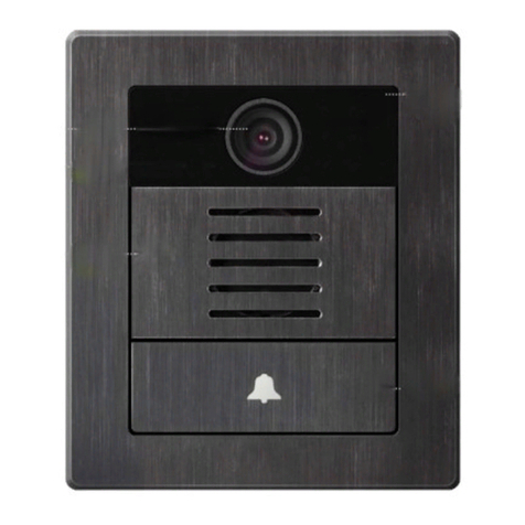
Figure 1: DB3100R

Amroad Technology Inc.
2
3
DB3100R VIDEO DOOR PHONE
General Application of Door Entry System
There are two major series of Video Door Phone: community series and single unit series. They are applied on dierent conditions.
DB3100R is designed for Unit in Luxury Apartment Building Application. It can work with IPBX servers to communicate with other
SIP-based devices. DB3100R works not only
as an intercom system but is also able to
integrate RFID card reader and connect to
other SIP devices to form a complete door
entry system.
Figure 2: Unit in Luxury Apartment Building Application
Unit in Luxury Apartment
Building
Unit in Luxury Apartment Building is illus-
trated. Please see Figure 2 for reference.
•Using a home IP PBX to connect all SIP-
based devices.
•Communicate with each device simply
with extension numbers.
•Connect to SIP VoIP services via Inter-
net.

Amroad Technology Inc.
3
MANUAL FOR SYSTEM INTEGRATOR
Use of SIP
SIP, initial of Session-Initiation-Proto-
col, it is an application-layer control
(signaling) protocol for creating, modi-
fying, and terminating sessions with
one or more participants. These ses-
sions include Internet telephone calls,
multimedia distribution, and multime-
dia conferences. In short, SIP is a most
commonly used protocol that has been
used to interconnect SIP Enabled PBXs
and/or SIP User Agents to each other
to establish voice and video sessions
between SIP based devices over IP
Network.
There are few typical applications of
SIP products, please refer to Figure 4:
•RingtheDoorBellfromVideoDoor
Phone (DB3100R) to IP Video Phone
(VP113/P)/Video Indoor Station
(ID5101)/IPC Softphone
•MakeaDB3100Rlive-videoviewphonecallfromIPCSoftphone/IPVideoPhone/VideoIndoorstation.
•MakeavideophonecallfromID5101VideoIndoorStationtoVP113IPvideophone.
Figure 3: General SIPApplication

Amroad Technology Inc.
4
5
DB3100R VIDEO DOOR PHONE

Amroad Technology Inc.
5
MANUAL FOR SYSTEM INTEGRATOR
Chapter 2 : Knowing Video Door Phone
Package Contents
The following items are included in your Video Door Phone package. Check this list before installation to ensure that you have received
all items.
1. Video Door Phone Main Unit
2. Front Panel
3. Flush-Mounted Box
4. 2-pin Terminal block
5. 5-pin Terminal block + Cord End Termi-
nal (7 pieces)
6. Screw Pack
7. Relay Board
8. Long Screws (x4)
9. Short Screws (x2)
10. Screws (for firmness in concrete)
11. Master RFID Card
12. H Type Terminal Connector for Power
Wire
13. Tool for removing the Front Panel from
Video Door Phone Unit
14. Quick Installation Guide & Quick Start
Guide (English and Chinese)
Please contact your dealer immediately if
any item(s) is missing.
Figure 4: Package Contents

Amroad Technology Inc.
6
7
DB3100R VIDEO DOOR PHONE
Front Panel
Figure 5: Front Panel

Amroad Technology Inc.
7
MANUAL FOR SYSTEM INTEGRATOR
Rear Panel & Side View
Figure 6: Rear Panel & Side View

Amroad Technology Inc.
8
9
DB3100R VIDEO DOOR PHONE
VOID Sticker
There is a “VOID” sticker on the left side of the DB3100R.
This VOID sticker is used to prevent opening the case and tampering concealment. Amroad shall not be respon-
sible under warranty if the VOID sticker is broken or removed.
WARNING: “VOID” means “WARRANTY VOID IF SEAL BROKEN”
Amroad shall not be responsible under warranty if the VOID sticker is broken or removed.

Amroad Technology Inc.
9
MANUAL FOR SYSTEM INTEGRATOR
Dimensions
Figure 7: Dimensions

Amroad Technology Inc.
10
11
DB3100R VIDEO DOOR PHONE

Amroad Technology Inc.
11
MANUAL FOR SYSTEM INTEGRATOR
Figure 8: Suggested Installation Position
Chapter 3 : Installing Video Door Phone
Suggested Installation Position
The view angle of the lens module is limited, so the installation position for Video
Door Phone is crucial. The video door phone comes with a Flush-Mounted Box. In order
to get a better view and the view angle of this door phone, the height of the bottom
of the Flush-Mounted Box is suggested about 141 cm far away from the ground (please
also refer to the diagram in the following sections) according to building conditions.
Please refer to the Figure.
View Angle
The Lens module of this device is able to see color images. To view clear live-video
images from IP Video Phone or Video Indoor Station, the view angle of this video door
phone should be less than 105o.
NOTE: The height of the camera lens is suggested at the distance of 155 cm above the
oor.

Amroad Technology Inc.
12
13
DB3100R VIDEO DOOR PHONE
Installion Procedures
1. Prepare Flush-Mounted Box
Before installing the Flush-Mounted Box, you can
fasten four screws on Flush-Mounted Box as shown in
Figure. This will make Flush-Mounted Box be mounted
on the wall more firmly and securely after grouting
foam concrete.
Use a Plug to connect Corrugated Tube to Flush-
Mounted Box. The corrugated tube allows cable and
wirings to pass through. The cable and wirings are Eth-
ernet cable, DC power, and Relay control.
Figure 9: Tighten four Screws and Connect Corrugated Tube

Amroad Technology Inc.
13
MANUAL FOR SYSTEM INTEGRATOR
2. Secure Flush-Mounted Box on Steel Frame
Before attaching Plaster Board and grouting Foam
Concrete on the wall, it’s necessary to secure Flush-
Mounted Box on Steel Frame.
The heights of the Steel Bars for installing Flush-
Mounted Box are suggested as shown in Figure.
The height between the bottom of the Flush-Mounted
Box and oor is 141 cm. And the depth of the Flush-
Mounted Box is 47.2mm.
Use four Drill Screws to secure Flush-Mounted Box on
Steel Bars in the Steel Frame. At the same time, a bub-
ble level is used to ensure Flush-Mounted Box is level.
Figure 10: Secure Flush Mounted Box to Steel Frame

Amroad Technology Inc.
14
15
DB3100R VIDEO DOOR PHONE
3. Wire and Cable Connection
Wire and cable go through wall and corrugated tube, and are used for DC power, network connection, and relay control. There are IO connectors on
the rear side of the DB3100R. They are for DC power, Ethernet port (RJ-45 connector), and GPIO wire. Please refer to the Figure and following sec-
tion- GPIO & Relay Control. For space saving, AR Relay Board can be placed on the top of the rear side and connect GPIO wires.
Figure 11: Wire and Cable Connection on the Rear Side of DB3100R

Amroad Technology Inc.
15
MANUAL FOR SYSTEM INTEGRATOR
4. Installing DB3100R Unit
Before installing DB3100R on the wall, Flush-Mounted Box should be first mounted on the wall firmly. The following diagram shows the
detail on how to install DB3100R Unit into Flush-Mounted Box.
Secure DB3100R Main Unit
to Flush-Mounted Box
by tightening four long
screws.
Then, attach Front Panel
by putting front cover on
DB3010R Main unit and
firmly press Front Panel to
snap into DB3100R Main
Unit. Lift Doorbell button
and use two short screws
to secure Front Panel.
NOTE:
Before securing DB3100R
Main Unit to Flush-Mount-
ed Box, you should have
connected Ethernet cable,
power wire, relay control
wiring. Figure 12: The details on how to install DB3100R Unit
Table of contents
Other Amroad Intercom System manuals

Amroad
Amroad DP101 User manual

Amroad
Amroad DP3210 User manual

Amroad
Amroad DP101 User manual

Amroad
Amroad ID5101 User manual

Amroad
Amroad AMROAD P3 User manual

Amroad
Amroad VP115 User manual

Amroad
Amroad DP3010R User manual

Amroad
Amroad AMROAD P3 User manual

Amroad
Amroad DP101R User manual

Amroad
Amroad DP3211 User manual

Amroad
Amroad DP3210 User manual

Amroad
Amroad DP3211 User manual

Amroad
Amroad DP3210 User manual

Amroad
Amroad DP100-25 User manual
Amroad
Amroad DP3010R User guide

Amroad
Amroad ID5101-RN User manual

Amroad
Amroad XL COMMUNITY STATION User manual

Amroad
Amroad DP101 Quick setup guide

Amroad
Amroad AMROAD P3 User manual

Amroad
Amroad DP100 User manual