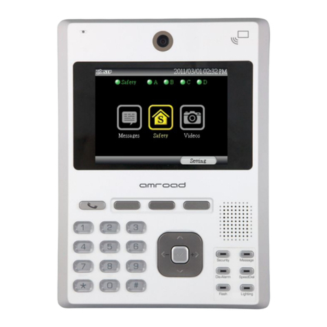
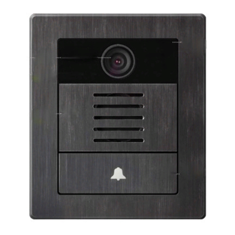
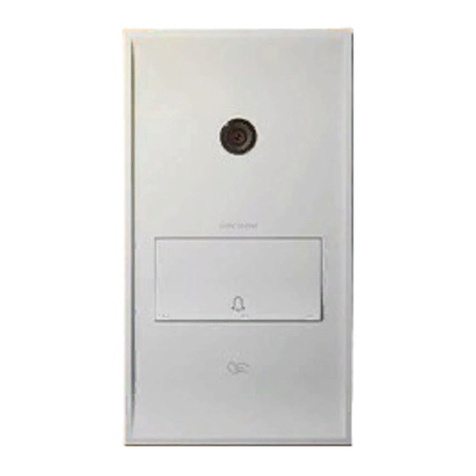
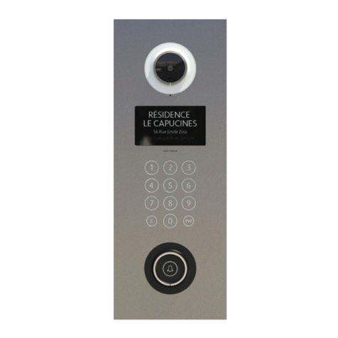
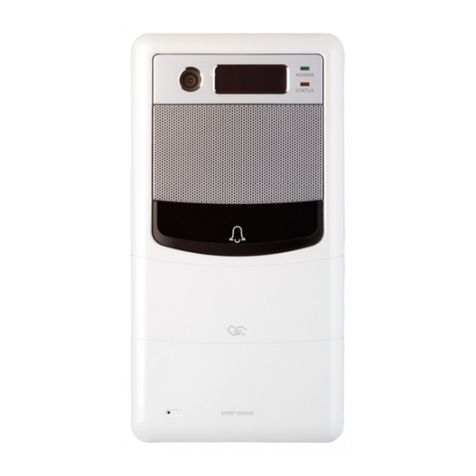
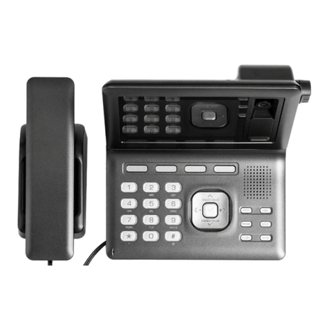
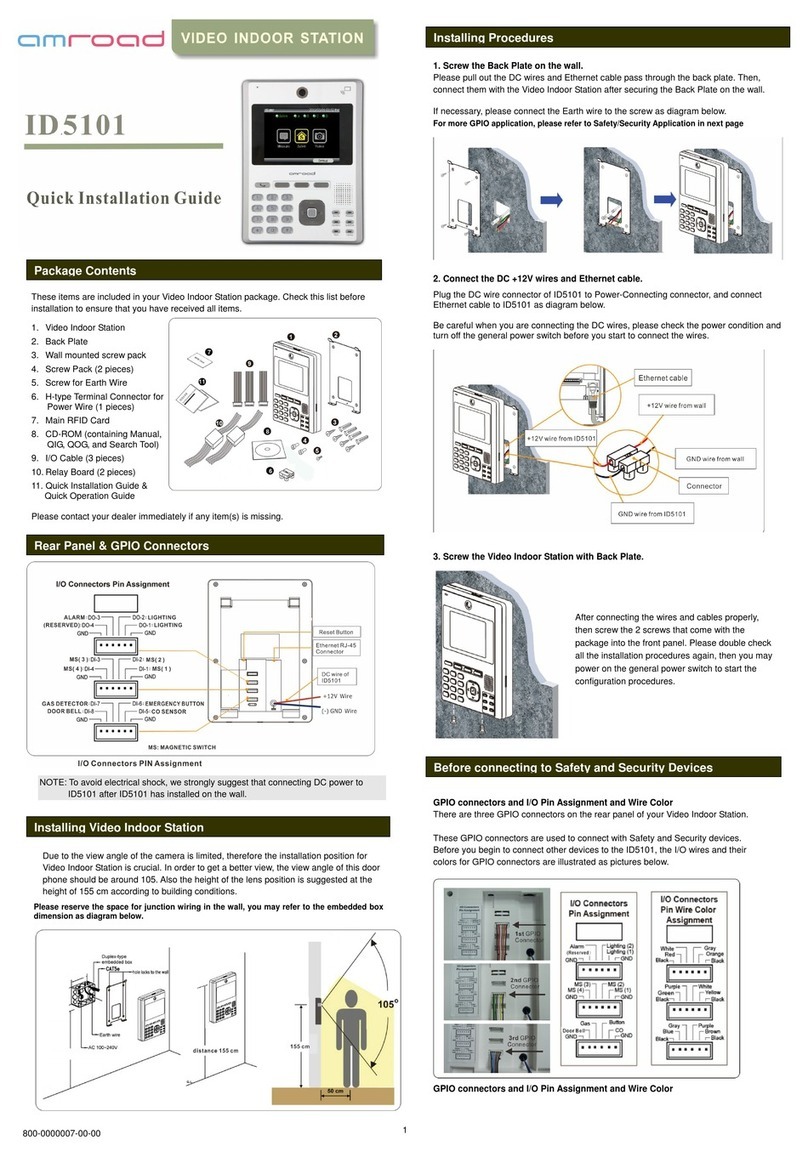
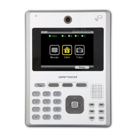
Amroad DP3210 User manual


COPYRIGHT
Copyright
© 2011 Amroad Technology Inc.
All Rights Reserved. No part of this publication may be reproduced, transmitted, transcribed, stored in a retrieval system or translated into
any language in any form or by any means without the express written permission of Amroad Technology Inc. To obtain consent, write to the
attention of Amroad Technology Inc.
Document No. DP3210 2012-0918
www.amroad.com.tw
DISCLAIMER
Amroad reserves the right to change product specification without prior notice.
Changes may be made to the information in this publication without obligation to notify. Amroad shall not be liable for technical or editorial
errors contained herein.
TRADE MARKS
Amroad logo is copyright of Amroad Technology Inc. All other products, services or trade marks mentioned in this document are the
property of their respective owners, companies or organizations.

CONTENTS
i
Contents
Copyright .........................................................................................................................................................................2
Contents ...........................................................................................................................................................................i
CHAPTER 1: INTRODUCTION ...........................................................................................................................................1
Welcome ..........................................................................................................................................................................1
Use of SIP .........................................................................................................................................................................4
CHAPTER 2:KNOWING VIDEO DOOR PHONE ....................................................................................................................6
Package Contents .............................................................................................................................................................6
Front Panel .......................................................................................................................................................................7
LED Indicators ..................................................................................................................................................................8
Rear Panel ......................................................................................................................................................................10
Dimensions ....................................................................................................................................................................11
CHAPTER 3:INSTALLING VIDEO DOOR PHONE.................................................................................................................13
Suggested Installation Position .......................................................................................................................................13
Lighting Condition ..........................................................................................................................................................13
Installing Procedures.......................................................................................................................................................14
1. Screw the Back Plate on the wall...............................................................................................................................................14
2. Connect the Ethernet Cable and DC wires .................................................................................................................................15
3. Screw the Video Door Phone with Back Plate. ...........................................................................................................................17
CHAPTER 4:CONFIGURING VIDEO DOOR PHONE .............................................................................................................19
Finding Video Door Phone on Networks ...........................................................................................................................19

ii
Entering Web User Interface............................................................................................................................................20
System ...........................................................................................................................................................................22
System Basic Settings ........................................................................................................................................................................22
System Login Name...........................................................................................................................................................................25
System Reboot ..................................................................................................................................................................................25
Streaming Settings .........................................................................................................................................................26
Video Settings...................................................................................................................................................................................26
Audio Setting ...................................................................................................................................................................................27
SIP Settings.....................................................................................................................................................................28
Entrance Setting .............................................................................................................................................................31
Upgrade .........................................................................................................................................................................34
Firmware Upgrade ............................................................................................................................................................................34
Config..............................................................................................................................................................................................35
APS..................................................................................................................................................................................................37
CHAPTER 5:USING VIDEO DOOR PHONE........................................................................................................................39
Ringing Door Bell from Video Door Phone ...........................................................................................................................................39
Answering Calls on IP Video Phone .....................................................................................................................................................39
Keypad Controls................................................................................................................................................................................39
Functions Performed by the IP-PBX (Compatible with Amroad IP-PBX) .............................................................................41
APPENDIX A:REGULATORY INFORMATION .....................................................................................................................43
FCC STATEMENT ...............................................................................................................................................................................43
FCC Radiation Exposure Statement ....................................................................................................................................................43
CE DECLARATION OF CONFORMITY (EUROPE) ...............................................................................................................44

CONTENTS


DP3210 VIDEO DOOR PHONE
1
Chapter 1: Introduction
Welcome
Thank you for choosing this Video Door Phone. This device is designed to work with IP Video Phone and other SIP devices to
compose a SIP based door entry system. Besides taking advantages of IP technologies, this system also can fully utilize the SIP
protocol to link to your SIP devices. It will work with most IP PBX systems supporting audio and video, and it can be set via a web
interface.
This product provides following features:
Talk to visitors with real time video and voice on IP Video Phone or Video
Indoor Station
SIP 2.0 (RFC3261) Compliant
Support H.263 video format.
Support G.711 audio formats.
Support Peer-to-Peer Mode
Build-in wide angle lens and white LED light-compensator.
Build-in speaker and microphone.
Water and dust resistance capabilities (IP55).
Web user interface for configuration and management.
Support PoE (Power over Ethernet, 802.3af) module (External power supply AC 48V)
Figure 1: DP3210

MANUAL FOR SYSTEM INTEGRATOR
2
Please read this user guide before installing the device. Please contact your dealers or system integrators if you have questions.

DP3210 VIDEO DOOR PHONE
3
General Application of Door Entry System
There are two major series of Video Door Phone: community series and single unit series. They are applied on different conditions.
Please see following descriptions:
Single Unit Application
Single unit series is designed for units of
apartment or single house. Please see Figure
2 for reference.
Using a home IP PBX to connect all
SIP-based devices.
Communicate with each device simply
with extension numbers.
Connect to SIP VoIP services via Internet.
Community Application
Community series is designed for building,
apartment or community. Please contact
with your local dealer about Amroad
DP3010R, and DP100.
Connect each house or apartment
Figure 2: Single Unit Application

MANUAL FOR SYSTEM INTEGRATOR
4
with a large IP PBX.
Inhabitants can check visitors with VP113/P, ID5101, monitor public
areas or call each others with extension numbers.
Connect to SIP VoIP services via Internet.
Use of SIP
SIP, initial of Session-Initiation-
Protocol, it is an application-layer
control (signaling) protocol for
creating, modifying, and
terminating sessions with one or
more participants. These sessions
include Internet telephone calls,
multimedia distribution, and
multimedia conferences. In short,
SIP is a most commonly used
protocol that has been used to
interconnect SIP Enabled PBXs
and/or SIP User Agents to each
other to establish voice and video
sessions between SIP based devices over IP Network. Figure 3: General SIP Application

DP3210 VIDEO DOOR PHONE
5
There are few typical applications of SIP products, please refer to Figure 3:
Ring the Door Bell from Video Door Phone (DP3210) to IP Video Phone (VP113/P)/Video Indoor Station (ID5101)/IPC
Softphone
Make a DP3210 live-video view phone call from IPC Softphone /IP Video Phone / Video Indoor station.
Make a video phone call from ID5101 Video Indoor Station to VP113 IP video phone.
View video from softphone on your computer.

MANUAL FOR SYSTEM INTEGRATOR
6
Chapter 2 : Knowing Video Door Phone
Package Contents
The following items are included in your Video Door Phone package. Check this list before installation to ensure that you
have received all items.
1. Video Door Phone Unit
2. Back Plate
3. Wall mounted screw pack
4. Screw Pack (2 pieces)
5. Screw for Earth Wire
6. 2-pin Terminal block
7. Cord End Terminal (2 pieces)
8. Quick Installation Guide
Please contact your dealer immediately if items are
missing.
Figure 4: Package Contents

DP3210 VIDEO DOOR PHONE
7
Front Panel
Figure 5: Front Panel

MANUAL FOR SYSTEM INTEGRATOR
8
LED Indicators
There are one 3-color LED Indicator and door bell button (green LED) on the front side of the video door phone. The following
table displays the status and their description.
Green LED Red LED BlueLED Door Bell Button
(Green LED) Description
OFF ON for 1 second OFF ON for 1 second Boot is initiated.
WL LED is also On for 1 second.
Blinking (3-sec On,
one-sec Off) OFF OFF OFF Boot procedure 1st stage, OS Initial
OFF ON OFF ON Boot procedure 2nd stage, AP Ready
ON OFF OFF OFF
Boot is completed, and the device works
normally. (SIP Mode- DHCP, Static IP, and PPPoE
connection mode)
ON OFF OFF ON When Door Bell is pressed, or it’s at night (SIP
Mode).
OFF OFF ON OFF Boot is completed. Device works normally.
(Peer-to-Peer Mode)
OFF OFF ON ON Door Bell is pressed, or it’s at night
(Peer-to-peer Mode).
Blinking (Green->,
Red->, Blue-> each
one-sec On)
Blinking (Green->,
Red->, Blue-> each
one-sec On)
Blinking (Green->,
Red->, Blue-> each
one-sec On)
OFF Firmware Upgrade
OFF OFF On 3 seconds Once OFF Reset! Device becomes Static IP mode.

DP3210 VIDEO DOOR PHONE
9
OFF OFF Blinking (3-sec On,
one-sec Off) OFF SIP is NOT registered.
OFF Blinking (3-sec Off,
one-sec On) OFF OFF Network is Disconnected.
OFF Blinking (One-sec
On, 3-sec Off) OFF OFF Network is connected, but the device fails to
obtain IP address.
OFF Blinking (One-sec
On, One-sec Off) OFF Blinking (One-sec On,
One-sec Off) Alarm is triggered.

MANUAL FOR SYSTEM INTEGRATOR
10
Rear Panel
Figure 6: Rear Panel
NOTE: Reset button is located just
behind rubber film (3). You may
use thin stick like paper clip to
press reset button.

DP3210 VIDEO DOOR PHONE
11
Dimensions
Figure 7: Dimensions

MANUAL FOR SYSTEM INTEGRATOR
12

DP3210 VIDEO DOOR PHONE
13
Chapter 3 : Installing Video Door Phone
Suggested Installation Position
The view angle of the lens module is limited, so the installation position for Video
Door Phone is crucial. In order to get a better view, the view angle of this door
phone should be around 105o. Also the height of the lens position is suggested at
the distance of 155cm according to building conditions. Please refer to Figure 8.
Lighting Condition
In order to get better visual quality, this product provides WL (white light) LED for
lighting at night or lower light condition. The Lens of this device is able to see WL
(White Light) LED light. In order to get a better view, the view angle of this door
phone should be around 105o. Also the height of the lens position is suggested at
the distance of 155cm according to building conditions.
WARNING: Avoid eyes exposure to the beam of the WL (White Light) LED for a
long time, or it may cause discomfort to your eyes.
Figure 8: Suggested Installation Position and Lighting Conditions

MANUAL FOR SYSTEM INTEGRATOR
14
Installing Procedures
1. Screw the Back Plate on the wall
Drill a hole that is able to let the 12VDC wires and Ethernet c able pass through. While
installing Back Plate, apply Silicon Glue to the both sides between Back Plate and Wall to
prevent rain/water from leaking into this device.
NOTE:
1. Reserve the space for junction wiring in the
wall.
2. The protective film on the DP3210 should
not be torn up during DP3210 installation.
Do not tear up the protective film until
new residents move in the house.
3. While installing DP3210's back plate, you
need to check the vertical and
horizontal directions of the back plate
in order to have a good appearance.
4. To prevent power surge and lighting strike
from damaging DP3210, back plate should
be connected to the ground wire (earth
wire) of the building, and power switching
from junction box should also be
connected to the ground wire (earth wire).
5. To conform to IP55 Enclosure, while
installing Back Plate, apply Silicon Glue to
the surface between Back Plate and Wall
to prevent rain/water from leaking into
this device.
Figure 9: Screw the Back Plate on the Wall
Other manuals for DP3210
2
Table of contents
Other Amroad Intercom System manuals

Amroad
Amroad AMROAD P3 User manual

Amroad
Amroad DP3010R User guide

Amroad
Amroad DP3010R User manual

Amroad
Amroad XL COMMUNITY STATION User manual

Amroad
Amroad DP3210 User manual

Amroad
Amroad DP100-25 User manual

Amroad
Amroad AMROAD P3 User manual

Amroad
Amroad ID5101 User manual

Amroad
Amroad ID5101 User manual

Amroad
Amroad DP3211 User manual

Amroad
Amroad DP101 Quick setup guide

Amroad
Amroad DP101 User manual

Amroad
Amroad DB3100R User manual

Amroad
Amroad DP3211 User manual

Amroad
Amroad DP3210 User manual

Amroad
Amroad VP115 User manual

Amroad
Amroad ID5101-RN User manual

Amroad
Amroad DP101 User manual

Amroad
Amroad AMROAD P3 User manual

Amroad
Amroad DP100 User manual