LCN 4040SE User manual

*24771*
24771
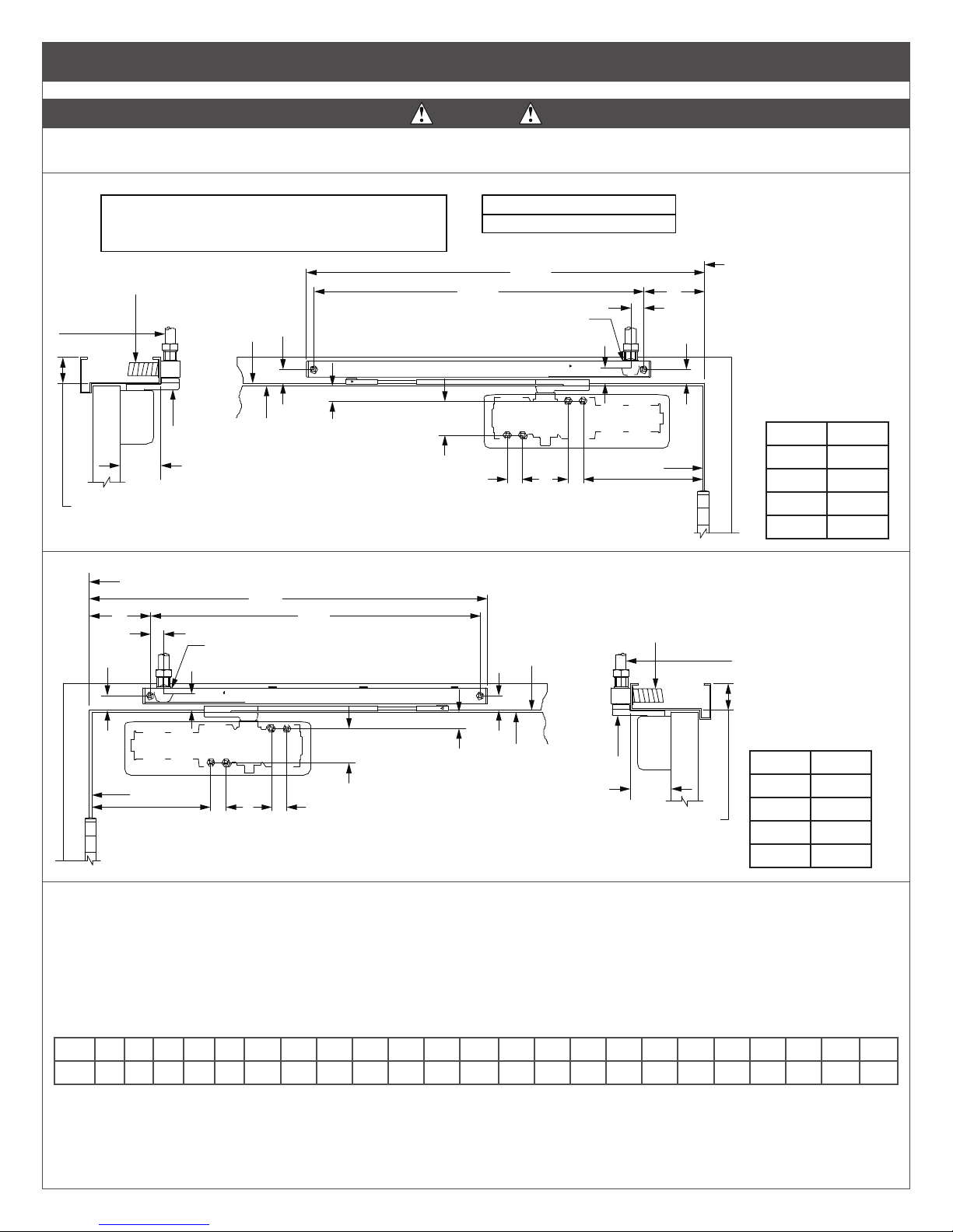
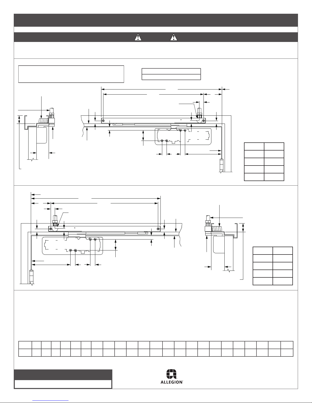
This closer features mounting options for both standard and step-down double egress frames. Before beginning, determine which type of
mounting best applies to your application, or has been specied for the job, then be sure to use the proper template.
Double Egress
4040SE
Installation Instructions
1 Voltage
The voltage shown on the track cover plate must match voltage
supplied to door frame (24V or 120V). If concealed wiring is
desired, prepare the frame to specications shown on the
corresponding template. If surface wiring is desired, be sure to
mount the track on the frame before running any EMT/conduit.
2 Track
Insert the proper track plugs into the top of the track. Using the
fasteners provided, mount the track on the frame to the template
dimensions being used. Make the electrical connections (see page
2).
3 Spring Power
Before mounting closer, the spring power may need adjusting.
Refer to the label on the closer spring tube. The 4040SE DE Series
comes preset at size 3. This will control a door up to 38”, adjust
the closer as shown (see illustration to the right) up to 7 full turns.
Starting the cover screws at this point is recommended. Using the
fasteners provided, mount the closer on the door to the dimensions
of the template being used.
4 Arm Installation
Place the arm spacer over the top shaft of the closer. Install the
arm as follows:
Place the arm spacer over the top shaft of the closer. Rotate the
arm from the door until ats in the arm hub line up with the rst
available ats of the shaft. Slide the arm hub onto the closer shaft.
Inser the shaft screw and tighten securely.
5 Arm Screw
Loosen the set screw in the arm. Connect the arm to the track
roller, and tighten the set screw rmly.
6 Door Position
To adjust the hold-open position of the door: Remove the screw
in the adjustable arm, and open the door to the desired position.
Reinsert the screw and tighten securely.
7 Regulation
Do not allow the door to slam into the frame. A “normal” closing
time from a 90° position is 5 to 7 seconds, evenly divided between
the Main and Latch Speed. If adjustments are needed, use a C\cx"
hex wrench. To adjust the Main Speed, turn the regulating screw
(see illustration) clockwise to slow the speed or c.c.w. to increase
the speed. Latch Speed is adjusted in the same way. When
adjusting, use the Backcheck the least amount necessary to slow
the swing of the door sufciently. To adjust the Backcheck, turn the
regulating screw clockwise to increase the amount of force or c.c.w.
to reduce the amount of force.
LNOTE: Do not use an abrupt backcheck setting or expect
the door closer to act as a stop!
8 Door Closer Cover
With regulation done, place the snap-on clip insert into the proper
cutout, then the snap cover assembly onto the spring tube.
CAUTION
Improper installation or regulation may result in personal
injury or property damage. Follow all instructions carefully.
For questions, call LCN at 877-671-7011.
Maximum Opening Force
=
35 ft-lbs
62 N
48 N-m
To
Increase
Power
Main
Speed
Latch
Speed
Backcheck
⁵⁄₃₂”
Hex
Wrench
Backcheck
Main
Speed
Latch
Speed

SE Mounting
WARNING
Hazardous voltage can shock and cause severe injury!
Disconnect the power before making any electrical connections or performing maintenance.
Hold-Open Force
Adjustment Screw
Solenoid
Assembly
Terminal
Leads
Ground
Terminal
Conduit
Hole Plug
Release
Test Switch
Wiring Diagram - Polarity Not Important
Input Voltage:
24v AC/DC Or 120v AC/DC
(Usually From Alarm Panel or Detector)
To Either Terminal
Optional Switch
To Either Terminal
SE
MOUNTING
ARM
ADJUST.
SCREW
COVER
PLATE
COVER
SCREW
SE TRACK
ASSEMBLY
SNAP ON
CLIP INSERT
(R.H. or L.H.)
SNAP ON
COVER
Note: Use screws for metal cover only.
TRACK
PLUG
(TOP)
END
PLUG
Hold-Open Force Adjustment:
Locate the hold-open adjustment screw in the diagram to the right. For greater hold-open force, insert a C\cx” hex wrench, and turn
clockwise. To decrease the amount of hold-open force, turn the screw counterclockwise, for a maximum of 4 turns.
Hold-Open Force
Adjustment Screw
Solenoid
Assembly
Terminal
Leads
Ground
Terminal
Conduit
Hole Plug
Release
Test Switch
Wiring Diagram - Polarity Not Important
Input Voltage:
24v AC/DC Or 120v AC/DC
(Usually From Alarm Panel or Detector)
To Either Terminal
Optional Switch
To Either Terminal
Arm
Adjust
Screw
Cover
Plate
Cover
Screw
SE Track
Assembly
Snap On
Clip Insert
(R.H. or L.H.)
Snap On
Cover
Note: Use Screws for Metal Cover Only.
Track
Plug
(Top)
End
Plug
Electrical Checkout
Hold-Open Force
Adjustment Screw
Solenoid
Assembly
Terminal
Leads
Ground
Terminal
Conduit
Hole Plug
Release
Test Switch
Wiring Diagram - Polarity Not Important
Input Voltage:
24v AC/DC Or 120v AC/DC
(Usually From Alarm Panel or Detector)
To Either Terminal
Optional Switch
To Either Terminal
Arm
Adjust
Screw
Cover
Plate
Cover
Screw
SE Track
Assembly
Snap On
Clip Insert
(R.H. or L.H.)
Snap On
Cover
Note: Use Screws for Metal Cover Only.
Track
Plug
(Top)
End
Plug
1. With power on, open the door. The door should remain in the open position. If the door does not stay open, check the electrical
output.
2. Push the release test switch. The door should close immediately. Open the door to the hold-open position and let it remain there.
3. The system should be checked at frequent intervals. It is suggested that Step 2 be repeated every 90 days.

4040SE-DE
WARNING
HAZARDOUS VOLTAGE CAN SHOCK AND CAUSE SEVERE INJURY!
Disconnect the power before making any electrical connections or performing maintenance.
DOOR HOLDER SOLENOID DATA
24VAC - DC Nominal =10% - 15% @ .090 Amp. Max.
120 VAC - DC Nominal =10% - 15% @ .030 Amp Max.
4040 SE DE Up To 95° Hold Open
Auxiliary Stop Recommended
Templating for Left Hand Door
Optional
Wiring
Connections
Jamb
Line
Jamb
Line
Hinge Edge
of Door
Double
Egress Arm
Top of
Door
2¹¹⁄₁₆
Max.
1³⁄₄ Min. for SE
2¹¹⁄₁₆ Hole for Electrical Connector
If Concealed Conduit Option Is Used
1
1
1¹⁄₈
1 3
26¹⁄₂
21³⁄₄ 4
⁷⁄₈
¹⁵⁄₁₆ 2¹⁄₄
1
Templating for Right Hand Door
Optional
Wiring
Connections
Jamb Line
Jamb
Line
Hinge Edge
of Door
Top of
Door Double
Egress Arm
2¹¹⁄₁₆
Max.
1³⁄₄ Min. for SE
1¹⁄₄ Hole for Electrical Connector if
Concealed Conduit Option Is Used
26¹⁄₄
21³⁄₄
4
1
1 1
2¹⁄₄
¹⁵⁄₁₆
1
3
1¹⁄₈
⁷⁄₈
Dim. Reveal
7M\, 2ZZ\zn
7C\, 2
6C\v 1Z\x
6Z\x 1
Notes:
1. The voltage supplied must match the voltage shown on the Sentronic label.
2. If the door is hung on pivots or swing clear hinges, consult the factory.
3. Floor or wall stops must be used.
4. For 7Z\v” or less double egress frames, the reveal should not exceed 2ZZ\zn”.
5. The Z\,” door-to-Soft clearance is required.
6. Reinforcing per ANSI/SDI-100 is recommended for hollow metal doors and frames.
7. The maximum butt hinge size is 5” x 5”.
Inch Z\, Z\v M\, ZB\zn 1 1Z\, 1Z\v 1Z\x 1C\v 2 2Z\v 2ZZ|zn 2M\, 3 4 5 6Z\x 6C\v 7Z\v 7C\, 7M\, 21C\v 26Z\v
M.M. 3 6 22 24 25 29 32 38 44 51 57 68 73 76 102 127 165 171 184 187 200 552 667

© Allegion 2014
Printed in U.S.A.
24771 Rev. 01/14-k
4040SE-DE: For B\,” Step-down frames
WARNING
HAZARDOUS VOLTAGE CAN SHOCK AND CAUSE SEVERE INJURY!
Disconnect the power before making any electrical connections or performing maintenance.
DOOR HOLDER SOLENOID DATA
24VAC - DC Nominal =10% - 15% @ .090 Amp. Max.
120 VAC - DC Nominal =10% - 15% @ .030 Amp Max.
4040 SE DE Up To 95° Hold Open
Auxiliary Stop Recommended
Templating for Left Hand Door
Optional
Wiring
Connections
Jamb
Line
Jamb
Line
Hinge Edge
of Door
Double
Egress Arm Top of
Door
2¹¹⁄₁₆
Max.
1¹⁄₂ Min. for SE
³⁄₄
⁵⁄₈
⁵⁄₈ ⁵⁄₈
⁷⁄₈
1 3
26¹⁄₄
21³⁄₄ 4
2¹⁄₄
1
1¹⁄₄ Hole for Electrical Connector if
Concealed Conduit Option Is Used
Templating for Right Hand Door
Optional
Wiring
Connections
Jamb Line
Jamb
Line
Hinge Edge
of Door
Top of
Door Double
Egress Arm
2¹¹⁄₁₆
Max.
1¹⁄₂ Min. for SE
1¹⁄₄ Hole for Electrical Connector if
Concealed Conduit Option Is Used
26¹⁄₄
21³⁄₄
4
1 1
2¹⁄₄
3
³⁄₄
⁵⁄₈
⁵⁄₈
⁵⁄₈
⁷⁄₈
Dim. Reveal
7M\, 2ZZ\zn
7C\, 2
6C\v 1Z\x
6Z\x 1
Notes:
1. The voltage supplied must match the voltage shown on the Sentronic label.
2. If the door is hung on pivots or swing clear hinges, consult the factory.
3. Floor or wall stops must be used.
4. For 7Z\v” or less double egress frames, the reveal should not exceed 2ZZ\zn”.
5. The Z\,” door-to-Soft clearance is required.
6. Reinforcing per ANSI/SDI-100 is recommended for hollow metal doors and frames.
7. The maximum butt hinge size is 5” x 5”.
Inch Z\, Z\v M\, ZB\zn 1 1Z\, 1Z\v 1Z\x 1C\v 2 2Z\v 2ZZ|zn 2M\, 3 4 5 6Z\x 6C\v 7Z\v 7C\, 7M\, 21C\v 26Z\v
M.M. 3 6 22 24 25 29 32 38 44 51 57 68 73 76 102 127 165 171 184 187 200 552 667
Customer Service
1-877-671-7011 www.allegion.com/us

Additional Notes: Revision History Revision Description:
K > Revised artwork
1. None J K L M N P
N/A 043228
Material
White Paper
Edited By Approved By EC Number Release Date
D. Myers M. Sasso 043228 01-01-14
Notes
1. printed two sides
2. printed black
3. tolerance ± .13
4. printed in country may vary
5. drawings not to scale
Title
4040SE Series Double Egress Instruction Sheet
Creation Date
04-27-10
Number
24771
Revision
K
Created By
N/A Activity
3899 Hancock Expwy
Security, CO 80911 © Allegion 2014Software: InDesign CS6
17.00
11.000
BEGINNING SHEET
Front
Page 1 Page 2 Page 3 Page 4
Back
4.25
11.000
FRONT
FOLDED SHEET
Table of contents
Other LCN Door Opening System manuals

LCN
LCN 3030 Series User manual

LCN
LCN 1450 Track Series User manual

LCN
LCN 3130-SEL Sentronic User manual

LCN
LCN 3130 Series User manual

LCN
LCN 1450 Series User manual

LCN
LCN COMPACT 6400 Series User manual

LCN
LCN Benchmark III 9140 User manual

LCN
LCN 2210DPS Series User manual

LCN
LCN 4840 User manual

LCN
LCN Sentronic 2310-ME User manual

LCN
LCN 2010 SERIES User manual

LCN
LCN 4031 CUSH User manual

LCN
LCN 4412 HSA Operation and maintenance manual

LCN
LCN 4630CS User manual

LCN
LCN 4050 Series User manual

LCN
LCN 1261 CUSH User manual

LCN
LCN 4410ME Series User manual

LCN
LCN 4020 Series User manual

LCN
LCN 8310-2420 User manual

LCN
LCN 4040XP User manual