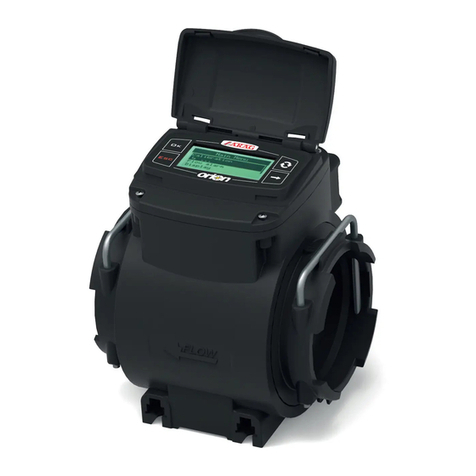
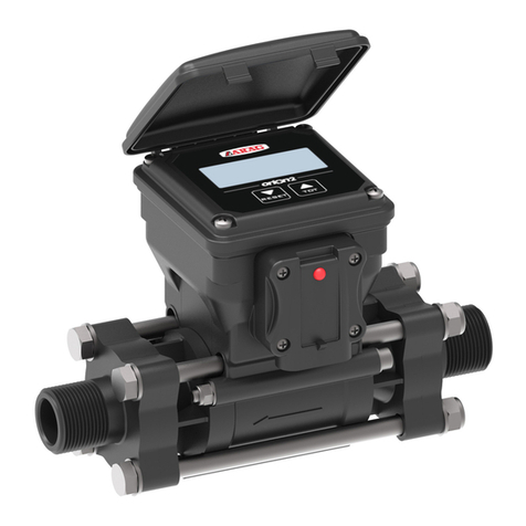
ARAG Orion Quick start guide

INSTALLATION, USE AND MAINTENANCE
4625AAGB1B1
MULTICHANNEL ELECTROMAGNETIC FLOWMETER
WITH CAN BUS CONNECTION
Software rel. 1.0.x

2
• LEGENDA SIMBOLI
=Generic danger
=Warning
1 Risks and protections before assembly...................................................................................................................................................... 3
2 Intended use .................................................................................................................................................................................................. 3
3 Package content ............................................................................................................................................................................................ 3
4 Position on farming machine ....................................................................................................................................................................... 4
5 Electric connections ..................................................................................................................................................................................... 6
5.1 General precautions for a correct harness position .............................................................................................................................. 6
6 Hydraulic connections .................................................................................................................................................................................. 7
6.1 General warnings.................................................................................................................................................................................. 7
6.2 Hydraulic connections........................................................................................................................................................................... 7
6.3 Accessories .......................................................................................................................................................................................... 7
7 Use.................................................................................................................................................................................................................. 8
7.1 Precautions ........................................................................................................................................................................................... 8
7.2 LED operation....................................................................................................................................................................................... 8
8 Maintenance................................................................................................................................................................................................... 9
8.1 Troubleshooting..................................................................................................................................................................................... 9
9 Technical data................................................................................................................................................................................................ 9
10 End-of-life disposal ..................................................................................................................................................................................... 10
11 Guarantee terms .......................................................................................................................................................................................... 10
This manual is an integral part of the equipment to which it refers and must accompany the equipment in case of sale or change of ownership. Keep it for future
reference; ARAG reserves the right to modify the specications and instructions regarding the product at any time and without prior notice.
LEGEND SYMBOLS
CONTENTS

3
1 RISKS AND PROTECTIONS BEFORE ASSEMBLY
All installation works must be done with battery disconnected, using suitable tools and any individual protection equipment
deemed necessary.
Use ONLY clean water for treatment tests and simulations: using chemicals during simulated treatment runs can seriously injure
persons in the vicinity.
2 INTENDED USE
Orion Multiow is an electro-magnetic owmeter with 4 channels designed to monitor liquid distribution systems.
The owmeter is provided with a CanBus port that allows its connection to the network with other owmeters to monitor up to 48 lines through a
single wiring.
This device is designed to work on agricultural machinery for crop spraying applications.
The machine is designed and built in compliance with EN ISO 14982 standard (Electromagnetic compatibility - Forestry and
farming machines), harmonized with 2004/108/EC Directive.
THE FLOWMETER MUST NOT BE USED TO MEASURE THE PASSAGE OF HYDROCARBONS, FLAMMABLE, EXPLOSIVE OR
TOXIC LIQUIDS. THE FLOWMETER IS NOT SUITABLE FOR CONTACT WITH LIQUIDS FOR HUMAN CONSUMPTION.
USE FOR SALES TRANSACTIONS IS NOT ALLOWED.
3 PACKAGE CONTENT
Fi g . 1
1. Orion Multiow
2. Instruction manual (DVD-ROM)
INTRODUCTION

4
4 POSITION ON FARMING MACHINE
Install the owmeter far from the elements that could cause turbulence inside the tubes (valves, bends, constrictions, etc.).
The owmeter can be installed in a horizontal or vertical position (Installation layout on page 5).
CAUTION:
For proper sealing of the owmeter, use EXCLUSIVELY ARAG ttings or accessories with T1 fork coupling
(Ref. ARAG General catalogue).
ARAG is not liable for damage to the system, persons, animals or things caused by the use of material other than specied.
- Install the owmeter using the suitable fasteners (Fig. 2): insert the hexagon-head screws (M8 or 5/16 UN) into their seats and slide them into the
latched position to keep them from coming off.
Fi g . 2
ITEM CONNECTION POINTS
1Power supply +
CanBus port
2Output signals in frequency
Tab. 1
Fi g . 3
INSTALLATION
CONTINUES

5
INSTALLATION
- To ensure trouble-free operation, comply with the indicated installation layout (Fig. 4 and Fig. 5);
HORIZONTAL ASSEMBLY
OK
OK
Fi g . 4
VERTICAL ASSEMBLY
OK
Fi g . 5
DO NOT FIT THE FLOWMETER WITH THE ELECTRIC CONNECTIONS FACING UP (Fig. 6).
Fi g . 6
- Comply with the correct uid inlet-outlet direction, as indicated by the arrow printed on the owmeter cover (Fig. 7).
IN
OUT
Fi g . 7 Fi g . 8

6
5 ELECTRIC CONNECTIONS
5.1 General precautions for a correct harness position
• Securing the cables:
- secure the harness so that it does not interfere with moving parts;
- route the harnesses so that they cannot be damaged or broken by machine movements or twisting.
• Fitting the cables to the connection points:
- Do not force the connectors by pushing too hard or bending them: the contacts may be damaged and device operation may be compromised.
Connect the wiring to the relevant connector; make sure it is correctly tted and push it until locking it.
The Orion Multiow owmeter has been designed to be connected to ARAG devices (computers, screens, displays) but can also be connected to
equipment made by other manufacturers as long as they are designed for owmeters of this typology.
ARAG is not liable for damage to the system, persons, animals or things caused by incorrect or inadequate installation of the
owmeter.
In the event of damage to the owmeter, caused by incorrect or unsuitable assembly, any form of guarantee is automatically
rendered null and void.
Fi g . 9
POWER SUPPLY + CANBUS
321
4
WARNING: if the owmeter is connected to
the Can-Bus line, it is not necessary to
connect the connector of the outputs in
frequency.
If you use the reading of the outputs in frequency,
it is necessary to use also the other connector
since it supplies the owmeter.
SIGNALS IN FREQUENCY
321
4
SUPERSEAL™ TE 4-POLE CONNECTOR
Position Connection
1GND
2+12 VDC
3CAN L
4CAN H
Tab. 2
SUPERSEAL™ TE 4-POLE CONNECTOR
Position Connection
1
Signal
(square wave)
CHANNEL A
2
Signal
(square wave)
CHANNEL B
3
Signal
(square wave)
CHANNEL C
4
Signal
(square wave)
CHANNEL D
Tab. 3
When the owmeter is connected to
this connector (signals in
frequency), it is necessary to set
the owmeter constant on the
device used to monitor the data.
INSTALLATION

7
INSTALLATION
6 HYDRAULIC CONNECTIONS
6.1 General warnings
Avoid bends and constrictions before connections and on tubes.
Do not use the owmeter at pressure values higher than the ones indicated in the technical specications.
Regarding connections, use tubes and ttings properly sized for the operating pressure of the system.
Use Arag T1 ttings (see general catalog) with male fork coupling. Do not use elbow ttings.
WARNING: For the implementation on already operating systems it is necessary to follow all safety rules described herein.
System assembly and start-up must be carried out by expert personnel according to the safety rules so as to ensure the same
safety level of the system.
6.2 Hydraulic connections
Connect the owmeter inlet and outlet pipes, using suitable connectors.
Take special care, where requested, to insert the supplied O-ring correctly(threaded ends). If, for any reason, the pipes leak at connection points,
apply unsintered PTFE tape to improve sealing.
Use inlet and outlet pipes of the same diameter as the internal passages of the owmeter; for further information, see Technical
data table on page 9.
6.3 Accessories
A 4-way modular manifold (with T3 fork coupling) is available to connect the owmeter inlets and/or for the connections of more owmeters in series
(ref. ARAG general catalog).
CODE 159431
T1 T1 T1 T1
T3
T3
End ttings with fork coupling and O-ring
in chapter“Fittings”(ref.ARAG general catalog).
Fi g . 10
Fi g . 11

8
7 USE
After switching on the owmeter, it will transmit through CANBUS all information regarding the device owrate and operation.
7.1 Precautions
- Do not aim pressurised water onto the equipment.
- Respect the device’s rated power requirement (12 Vdc).
- If arc welding is required, ensure that owmeter power is off and disconnect the power cables, if necessary.
- Use the owmeter only within the ow limits given in the “Technical data” table. Outside these limits, the owmeter could give
incorrect data and therefore lead the operator or the automatic system to make errors.
ARAG cannot be held responsible for damage caused to persons, animals or things by incorrect or unsuitable use of the
owmeter or its parts.
7.2 LED operation
Each type of ashing corresponds to signal, as indicated in Ta b . 4 :
LED SIGNAL SIGNALLED STATUS
1. Device connected to the owmeter WITHOUT identication no.:
alternate ashing of the LED pairs A-Band C-D.
Switching on.
After the rst 4 seconds from the switching on, the LEDs indicate the operation
status.
Perform the identication procedure described in the manual of the connected
monitor.
2. Identied device (ID1 ÷ 100):
the LED number and sequence indicate the assigned ID (Ta b. 5 ).
Switching on.
After the rst 4 seconds from the switching on, the LEDs indicate the operation
status.
3. Flashing of LEDs on the channels with owing liquid, with frequency propor-
tional to the measured owrate Flowing liquid.
4. Slow ashing of the LEDs on the channels without liquid
(2.8 s LED ON, 0.2 s LED OFF) Liquid not owing.
5. Slow ashing of the LEDs on the channels without liquid
(0.2 s LED ON, 2.8 s LED OFF) Missing liquid.
6. Alternate ashing of LEDs on channels Aand DFirmware update through CanBus.
7. Fast ashing of all LEDs (all channels) Software error: perform the rmware update procedure.
8. All LEDs on.
Hardware/software failure or CPU not programmed:
• Perform the rmware update procedure.
• Contact the ARAG Service Center.
Tab. 4
ID
LED SIGNAL
CHANNEL
A
CHANNEL
B
CHANNEL
C
CHANNEL
D
1
2
3
4
5
6
7
8
9
10
11
12
13
14
15
16
Tab. 5
USE

9
8 MAINTENANCE
- After every spraying operation, ush the pipe with clean water.
- In case of malfunction, and at any rate at the end of every season, clean the owmeter pipe with a special detergent.
- Do not use metal or abrasive objects for cleaning the duct.
- Do not use solvents or petrol for cleaning the external parts of the device.
8.1 Troubleshooting
FAULT CAUSE REMEDY
The LEDs do not turn on No power supply • Check the owmeter wiring.
The value read by the owmeter is not linear or stable Presence of turbulence or air in the circuit • Check the circuit.
Tab. 6
9 TECHNICAL DATA
Description Orion Multiow
Power supply 9 ÷ 15 Vdc
Max. absorption 600 mA
Min. liquid conductivity 50 µScm
Working temperature 0 °C ÷ 60 °C
+32 °F ÷ +140 °F
Storage temperature -20 °C ÷ 80 °C
-4 °F ÷ +176 F
Flowrate 0.3 ÷ 6 l/min
0.08 ÷ 1.6 US GPM
Internal passages 4 mm
Flowmeter constant 6000 pls/l
22710 US Gal
Max. pressure 20 bar
290 PSI
Couplings T1 F
Weight 1615 g
Tab. 7
MAINTENANCE / DIAGNOSTICS / REPAIRS - TECHNICAL DATA

10
10 END-OF-LIFE DISPOSAL
This device contains a lithium polymer battery that, at end of life, must be disposed of according to the prevailing rules.
11 GUARANTEE TERMS
1. ARAG s.r.l. guarantees this apparatus for a period of 360 days (1 year) from the date of sale to the client user (date of the goods delivery
note).
The components of the apparatus, that in the unappealable opinion of ARAG are faulty due to an original defect in the material or
production process, will be repaired or replaced free of charge at the nearest Assistance Center operating at the moment the request for
intervention is made. The following costs are excluded:
- disassembly and reassembly of the apparatus from the original system;
- transport of the apparatus to the Assistance Center.
2. The following are not covered by the guarantee:
- damage caused by transport (scratches, dents and similar);
- damage due to incorrect installation or to faults originating from insufficient or inadequate characteristics of the electrical system, or to
alterations resulting from environmental, climatic or other conditions;
- damage due to the use of unsuitable chemical products, for spraying, watering, weedkilling or any other crop treatment, that may damage
the apparatus;
- malfunctioning caused by negligence, mishandling, lack of know how, repairs or modications carried out by unauthorized personnel;
- incorrect installation and regulation;
- damage or malfunction caused by the lack of ordinary maintenance, such as cleaning of lters, nozzles, etc.;
- anything that can be considered to be normal wear and tear.
3. Repairing the apparatus will be carried out within time limits compatible with the organizational needs of the Assistance Center.
No guarantee conditions will be recognized for those units or components that have not been previously washed and cleaned to remove
residue of the products used;
4. Repairs carried out under guarantee are guaranteed for one year (360 days) from the replacement or repair date.
5. ARAG will not recognize any further expressed or intended guarantees, apart from those listed here.
No representative or retailer is authorized to take on any other responsibility relative to ARAG products.
The period of the guarantees recognized by law, including the commercial guarantees and allowances for special purposes are limited, in
length of time, to the validities given here.
In no case will ARAG recognize loss of prots, either direct, indirect, special or subsequent to any damage.
6. The parts replaced under guarantee remain the property of ARAG.
7. All safety information present in the sales documents regarding limits in use, performance and product characteristics must be transferred
to the end user as a responsibility of the purchaser.
8. Any controversy must be presented to the Reggio Emilia Law Court.

D20325_GB-m00 07/2015
42048 RUBIERA (Reggio Emilia) - ITALY
Via Palladio, 5/A
Tel. +39 0522 622011
Fax +39 0522 628944
http://www.aragnet.com
info@aragnet.com
Only use genuine ARAG accessories or spare parts to make sure manufacturer guaranteed safety conditions are maintained in time. Always refer to ARAG spare
parts catalog.
Table of contents
Other ARAG Measuring Instrument manuals

ARAG
ARAG DigiWOLF 4627 Series Quick start guide

ARAG
ARAG orionX Quick start guide

ARAG
ARAG DigiWOLF 4628405 User manual

ARAG
ARAG orion 462A Series Quick start guide

ARAG
ARAG Orion 2 46211A Series Quick start guide

ARAG
ARAG Visio User manual

ARAG
ARAG Orion 2 VisualFlow 46212A Series Quick start guide

ARAG
ARAG alfa 310S User manual

ARAG
ARAG 853 Series Service manual
Popular Measuring Instrument manuals by other brands

Ocean Optics
Ocean Optics HR2000+ Installation and operation manual

Agilent Technologies
Agilent Technologies 85103E installation manual

Cutler-Hammer
Cutler-Hammer IQ Analyzer quick start guide

Miros
Miros SM-140 Series user manual

Keithley
Keithley 595 instruction manual

OrienTek
OrienTek TPM-35m quick start guide