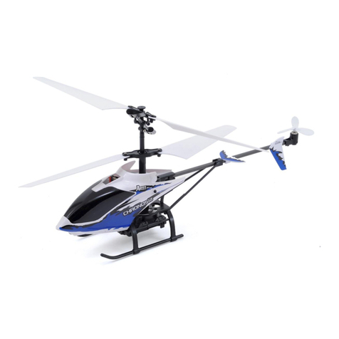
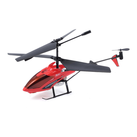
Ares Chronos FP 110 User manual

Instruction Manual
Specifications
Length: 11.6 in (295mm)
Height: 4.3 in (110mm)
Main Rotor Diameter: 11.6 in (295mm)
Weight with Baery: 3.2 oz (90g)
Main Motor: N40 (installed)
Tail Motor: Micro-Coreless (installed)
Baery: 500mAh 1S 3.7VLiPo (included)
Charger: 1S 3.7V LiPo AC (included)
Transmier: 4-channel 2.4GHz (included)
On-Board Electronics: 4-in-1 receiver/2 ESCs/mixer/gyro and 2 servos (included)

Specificaons ........................................................................................................................................... 1
Introducon ............................................................................................................................................. 3
Safety Precauons and Warnings ............................................................................................................ 3
FCC Informaon ....................................................................................................................................... 4
Chronos FP 110 RTF Contents .................................................................................................................. 4
Required to Complete .............................................................................................................................. 5
Before the First Flight Checklist ............................................................................................................... 5
Flight Checklist ......................................................................................................................................... 5
LiPo Baery Warnings and Usage Guidlines ............................................................................................ 6
Charging the LiPo Baery ........................................................................................................................ 7
Installing the Transmier Baeries .......................................................................................................... 9
Transmier Details ................................................................................................................................... 9
Proporonal Mix Trimmer Knob .............................................................................................................. 10
Transmier Dual Rates ............................................................................................................................11
Flight Controls and Trimming ................................................................................................................... 12
Installing and Removing the LiPo Flight Baery ....................................................................................... 18
Control Unit Inializaon, Arming and Motor Control Test ..................................................................... 18
Motor Control Test ..................................................................................................................................21
Selecng a Flying Area ............................................................................................................................. 22
Flying (General) ....................................................................................................................................... 23
Flying Outdoors .................................................................................................................................... 25
Transmier and Receiver Binding/Linking ............................................................................................... 26
Warranty, Support and Service ................................................................................................................ 26
Notes .......................................................................................................................................................27
Replacement Parts List ............................................................................................................................ 28
Exploded View Parts Lisng .................................................................................................................... 28
Exploded View ........................................................................................................................................ 30
Notes ....................................................................................................................................................... 31
Table of Contents
2

Introduction
When you’re ready to make the move from mul-rotor and coaxial to single-rotor heli flying there’s no
beer choice than the Ares™ [air-eez] Chronos FP 110. The advanced fixed-pitch and self-stabilizing rotor
head design offers the agility and maneuverability of a single-rotor heli along with the stability of a
coaxial heli so you can learn the basics of more advanced flying with confidence and in less me than
ever before.
The ultra-micro sized Chronos FP 110 is larger than similar class helis for improved performance and
handling when flying outdoors in winds up to 5-7 mph yet it’s sll small enough to fly comfortably indoors
too. It’s also equipped with class-leading features including separate 1.7-gram digital servos, a quiet and
efficient two-stage gear train plus a lightweight and durable airframe that arrives 100%
factory-assembled and ready-to-fly right out of the box!
And although the Chronos FP 110 is ready to fly right out the box, please take the me to read through
this manual for more informaon on baery safety and charging, flight controls and more before
proceeding with your first flight. Please also visit our web site at www.Ares-RC.com for addional
informaon including potenal product bullens, videos and more.
Safety Precautions and Warnings
Failure to use this product in the intended manner as described in the following instrucons can result
in damage and/or personal injury. A Radio Controlled (RC) airplane/helicopter/quadcopter is not a toy!
If misused it can cause serious bodily harm and damage to property.
Keep items that could become entangled in the propeller/rotor blades away from the propeller/rotor
blades, including loose clothing, tools, etc. Be especially sure to keep your hands, face and other parts
of your body away from the propeller/rotor blades.
As the user of this product you are solely and wholly responsible for operang it in a manner that does
not endanger yourself and others or result in damage to the product or the property of others.
This model is controlled by a radio signal that is subject to possible interference from a variety of
sources outside your control. This interference can cause momentary loss of control so it is advisable
to always keep a safe distance from objects and people in all direcons around your model as this will
help to avoid collisions and/or injury.
• Never operate your model if the voltage of the baeries in the transmier is too low.
• Always operate your model in an open area away from obstacles, people, vehicles, buildings,
etc.
• Carefully follow the direcons and warnings for this and any oponal support equipment
(chargers, rechargeable baeries, etc.).
• Keep all chemicals, small parts and all electronic components out of the reach of children.
• Moisture causes damage to electronic components. Avoid water exposure to all electronic
components, parts, etc. not specifically designed and protected for use in water.
• Never lick or place any poron of the model in your mouth as it could cause serious injury or
even death.
3
FCC Information
This device complies with part 15 of the FCC rules. Operaon is subject to the following two condions:
(1) This device may not cause harmful interference, and (2) this device must accept any interference
received, including interference that may cause undesired operaon.
Cauon: Changes or modificaons not expressly approved by the party responsible for compliance could
void the user’s authority to operate the equipment.
This product contains a radio transmier with wireless technology which has been tested and found to
be compliant with the applicable regulaons governing a radio transmier in the 2.400GHz to 2.4835GHz
frequency range.
The associated regulatory agencies of the following countries recognize the noted cerficaons for this
product as authorized for sale and use: USA
Chronos FP 110 RTF Contents
Item Descripon
Not Available Separately .................. Chronos FP 110 RTF Airframe
AZSH1258MD2 ................................. M4LPH 4-Channel Helicopter Transmier, Mode 2
Not Available Separately .................. AA Baeries (6pcs)
AZSH1255 ........................................ 500mAh 1-Cell/1S 3.7V 15C LiPo Baery, JST Connector
AZSH1254 ........................................ 1-Cell/1S 3.7V LiPo, 0.5A 110-240V AC Charger
4

Required to Complete
The Chronos FP 110 RTF includes everything needed to fly right out of the box. There’s nothing extra to
buy or provide!
Before the First Flight Checklist
PLEASE NOTE: This checklist is NOT intended to replace the content included in this instrucon
manual. Although it can be used as a quick start guide, we strongly suggest reading through this
manual completely before proceeding.
• Remove and inspect all contents
• Plug the AC charger into a suitable outlet/power source
• Begin charging the LiPo flight baery (connect it to the charger)
• Install the six (6) AA baeries in the transmier
• Install the LiPo flight baery in the helicopter (aer it’s been fully charged) and connect it
to the control unit
• Test the controls to confirm proper operaon
• Familiarize yourself with the controls
• Find a suitable area for flying
Flight Checklist
PLEASE NOTE: This checklist is NOT intended to replace the content included in this instrucon
manual. Although it can be used as a quick start guide, we strongly suggest reading through this
manual completely before proceeding.
• Always turn the transmier on first
• Connect the LiPo flight baery to the control unit
• Allow the control unit to inialize and arm properly
• Fly the model (take-off from a flat/level surface)
• Land the model (land on a flat/level surface)
• Disconnect the LiPo flight baery from the control unit
• Always turn the transmier off last
5

LiPo Battery Warnings and Usage Guidelines
IMPORTANT NOTE: Lithium Polymer baeries are significantly more volale than the alkaline, NiCd or
NiMH baeries also used in RC applicaons. All instrucons and warnings must be followed exactly to
prevent property damage and/or personal injury as mishandling of LiPo baeries can result in fire.
By handling, charging or using the included LiPo baery you assume all risks associated with LiPo
baeries. If you do not agree with these condions please return the complete product in new, unused
condion to the place of purchase immediately.
And although the 500mAh 1-Cell/1S 3.7V 15C LiPo Baery (AZSH1255) included with the RTF version
Chronos FP 110 is intended to be charged safely using the included 1-Cell/1S 3.7V LiPo, 0.5A 110-240V
AC Charger (AZSH1254) you must read the following safety instrucons and warnings before handling,
charging or using the LiPo baery.
• You must charge the LiPo baery in a safe area away from flammable materials.
• Never charge the LiPo baery unaended at any me. When charging the baery you should
always remain in constant observaon to monitor the charging process and react immediately
to any potenal problems that may occur.
• Aer flying/discharging the baery you must allow it to cool to ambient/room temperature
before recharging.
• To charge the LiPo baery you must use only the included 1-Cell/1S 3.7V LiPo, 0.5A 110-240V AC
Charger (AZSH1254) or a suitably compable LiPo baery charger. Failure to do so may result in
a fire causing property damage and/or personal injury. DO NOT use a NiCd or NiMH charger.
• If at any me during the charge or discharge process the baery begins to balloon or swell,
disconnue charging or discharging immediately. Quickly and safely disconnect the baery,
then place it in a safe, open area away from flammable materials to observe for at least 15
minutes. Connuing to charge or discharge a baery that has begun to balloon or swell can
result in a fire. A baery that has ballooned or swollen even a small amount must be removed
from service completely.
• Store the baery at room temperature, approximately 68–77° Fahrenheit (F), and in a dry area
for best results.
• When transporng or temporarily storing the baery, the temperature range should be from
approximately 40–100°F. Do not store the baery or model in a hot garage, car or direct
sunlight whenever possible. If stored in a hot garage or car the baery can be damaged or even
catch fire.
6

• Do not over-discharge the LiPo baery. Discharging the LiPo baery too low can cause
damage to the baery resulng in reduced power, flight duraon or failure of the baery
enrely.
LiPo cells should not be discharged to below 3.0V each under load. In the case of the
1-Cell/1S 3.7V LiPo baery used to power the Chronos FP 110, you will not want to allow the
baery to fall below 3.0V during flight.
The 4-in-1 control unit does not feature a low voltage cutoff (LVC) of any type so it’s important
for you to be aware of the power level of the LiPo baery during flight. If you ever find that
more than the typical amount of throle/power is required to hover and/or the helicopter will
not ascend/climb even at full power you should land the model and disconnect the baery
immediately to prevent over-discharge. Connued discharging can cause permanent damage
to the LiPo baery resulng in reduced power output and/or shortened flight duraons during
subsequent flights (or failure of the baery enrely).
Charging the LiPo Battery
You must charge the included 500mAh 1-Cell/1S 3.7V 15C LiPo Baery (AZSH1255) using only the
included 1-Cell/1S 3.7V LiPo, 0.5A 110-240V AC Charger (AZSH1254) or a suitably compable LiPo
baery charger. Charging the LiPo baery using a non-LiPo baery compable charger (such as a NiCd
or NiMH baery charger), or even a different LiPo baery charger w ith the incorrect sengs, may
result in damage to the baery or even fire resulng in property damage and/or personal injury.
Please follow these steps to charge the LiPo flight baery with the included charger:
• Plug the AC charger into a compable 110-240V AC outlet. The LED indicator will glow solid
green indicang that the charger is powered on and ready to charge.
• Connect the red JST connector on the baery to the mang connector on the charger.
YOU MUST BE CAREFUL TO ENSURE PROPER POLARITY BEFORE MAKING THE CONNECTION.
By orientang/aligning the wire leads of the baery and charger so they’re ‘red to red’ and
‘black to black’ you’ll be able to make the connecon with correct polarity. And although the
red JST connectors are ‘keyed’ to minimize the risk of a reverse polarity connecon, if you force
them it is possible to make connecon with the incorrect polarity potenally causing damage to
the baery and/or charger. When the connectors are properly aligned for correct polarity,
connecng them should require only a moderate amount of pressure to achieve the ‘click’ that
indicates a secure connecon.
7

• When the baery is connected to the charger securely and with the proper polarity the LED
indicator will glow solid red. The baery will be charging anyme the LED indicator is glowing
solid red.
• It will take approximately 1.0–1.5 hours to fully charge a mostly or fully discharged
(not over-discharged) baery. And when the baery is fully charged the LED indicator will
change to glow solid green. When the LED is glowing solid green you can disconnect the
baery from the charger as it is now fully charged and ready for use.
NOTE: The LiPo baery included with your model will arrive parally charged. For this reason the
inial charge may only take approximately 30–45 minutes.
NOTE: It’s safer and beer for the longevity of the baery to store it only parally charged for any
length of me. Storing the baery at approximately 50% charge (which is approximately 3.85V per
cell) is typically best, however, it will take some careful management of the charge me and the use
of a volt meter to achieve this voltage. If you have the equipment and skills to achieve the 50% charge
level for storage it is recommended. If not, simply be sure to not store the baery fully charged
whenever possible. In fact, as long as the baery will be stored at approximately room temperature
and for no more than a few weeks before the next use, it may be best to store the baery in the
discharged state aer the last flight (as long as the baery was not over-discharged on the last flight).
8

Installing Transmitter Batteries
Install the six included AA baeries in the back of the transmier by removing the screw securing the
baery compartment cover/door then remove the baery compartment cover/door. Ensure proper
polarity of the baeries before installing them as indicated by the markings molded into the baery
compartment, then re-install the compartment cover/door and screw.
Check for proper operaon of the transmier by switching the power switch ON (slide it upward). The
LED indicator near the top right-hand corner should glow solid red while the LCD screen powers on to
display various data. These indicaons confirm the transmier is powered on and funconing correctly.
NOTE: The transmier is equipped with a low voltage baery alarm. If at any me the audible alarm is
on it will be necessary to replace the AA baeries with new ones.
Transmitter Details
The Chronos FP 110 includes an M4LPH Micro 4-Channel Helicopter Transmier equipped with 2.4GHz
technology, dual rates, digital trims and an LCD screen.
9

Proporonal Mix Trimmer Knob
The knob located near the top le-hand corner of the transmier is used to adjust the amount of ‘mixing’
between the main and tail motors. Please see the ‘Proporonal Mix Trimmer Knob’ secon of this
manual for more informaon.
Dual Rate Buon
The buon located near the top right-hand corner of the transmier is used to toggle between the ‘Dual
Rates’ available for the aileron and elevator controls/channels. Please see the ‘Transmier Dual Rates’
secon of this manual for more informaon.
Also, the LCD screen displays a variety of data when the transmier is powered on:
Proportional Mix Trimmer Knob
The M4LPH transmier is equipped with a
‘PROPORTIONAL’ mix trimmer knob (located
near the top le-hand corner of the transmit-
ter) that adjusts the amount of ‘mixing’
between the main and tail motors. This allows
you to fine-tune the rudder trim/sub-trim to
help prevent the nose of the helicopter from
driing to the le or right when in hover and
when climbing/descending.
10

NOTE: All Chronos FP 110 helicopters are test-flown at the factory. And during each test flight the
posion/seng for the proporonal mix trimmer knob is typically adjusted to provide very good trim
and performance overall. However, it is possible for the posion of the knob to change during handling
of the transmier so it may be necessary to adjust the posion/seng of the knob to achieve the best
possible trim and performance. And if you find it necessary to adjust the posion/seng of the knob
please follow these steps:
• Establish a stable hover and, with the rudder trim ‘centered’ and no rudder control input, check
to see if the nose of the helicopter is driing in one direcon or the other. If the nose of the
helicopter is driing to the le, turn the proporonal mix trimmer knob clockwise (+) as needed
to minimize/eliminate the driing.
• If the nose of the helicopter is driing to the right, turn the proporonal mix trimmer knob
counterclockwise (-) as needed to minimize/eliminate the driing.
QUICK TIP: As the motors heat up and the baery’s output voltage decreases throughout the flight, it
may be necessary to adjust the rudder trim posion/seng slightly to keep the nose of the helicopter
from driing to the le or right. These small adjustments can be made using the rudder trim and do
not typically require addional adjustment of the proporonal mix trimmer knob.
Transmitter Dual Rates
11
The ‘DUAL RATE’ buon (located near the top
right-hand corner of the transmier) is used to the
toggle between the ‘High’ (HI) and ‘Low’ (LO)
control rates, also known as ‘Dual Rates’, available
for the aileron and elevator controls/channels.
When the LED indicator is ON and glowing solid red
the control rate is set to ‘HI’ and the controls are
allowed to reach their maximum (high)
rates/values. This mode is typically preferred by
experienced pilots interested most in maximum
control authority.
When the LED indicator is OFF the control rate is set to ‘LO’ and the maximum control rates/values will
be reduced for the aileron and elevator channels. This is typically preferred by (and recommended best
for) low-me and other pilots interested in a reduced amount of control authority that allows for even
smoother and more easily controlled hovering/flying.
NOTE: Each me the transmier is powered off then on again the dual rates will default to HI.

Flight Controls and Trimming
In the event you are not familiar with the controls of the Chronos FP 110 please take the me to
familiarize yourself with them as follows and before proceeding with your first flight:
The le-hand sck on the transmier controls both the throle (climb/descend) and rudder (yaw
le/right) channels. When the le-hand sck (also known as the ‘throle’ sck) is in the lowest possible
posion the rotor blades will not spin. Moving the sck upward will increase the speed/RPMs of the rotor
blades. Increasing the speed/RPMs of the rotor blades will cause the model to climb.
Decreasing the speed/RPMs of the rotor blades by lowering the le-hand sck will cause the model to
descend.
Aer liing the helicopter off the ground you can maintain altude in ‘hover’ by carefully moving the
le-hand sck up and down slightly as needed so the helicopter will not climb or descend.
12

The throle trim lever (located immediately to the right of the le-hand/throle sck) can be used to
adjust the throle control/channel output value for a given sck posion. For example, raising the throle
trim will make it possible to maintain altude with the helicopter when the le-hand/throle sck is in a
lower posion. However, we do not typically recommend raising or lowering the throle trim above/below
the middle/centered posion.
IMPORTANT NOTE: If you do raise the throle trim you
MUST remember to lower it to the middle/centered
posion AND the throle sck to the lowest possible
posion IMMEDIATELY in the event of a crash or rotor
blade strike. Failure to lower the throle trim to the
middle/centered posion and throle sck to the lowest
possible posion immediately in the event of a crash/rotor
blade strike can result in damage to the ESCs in the 4-in-1
control unit (which may require replacement of the control
unit).
Moving the le-hand sck to the le will turn (yaw) the nose of the helicopter to the le about the axis of
the main sha. This is accomplished by decreasing the speed/RPMs of the tail rotor.
13

Moving the le-hand sck to the right will turn (yaw) the nose of the helicopter to the right about the
axis of the main sha. This is accomplished by increasing the speed/RPMs of the tail rotor.
The rudder trim lever (located immediately below the le-hand sck) can be used to help keep the nose
of the helicopter from turning (yawing) to the le or right when ‘hovering’ and without any le-hand
sck/rudder control input. For example, if the nose of the helicopter turns to the right when hovering
add le rudder trim by pressing the lever to the le unl the nose of the helicopter stays as close to
‘straight’ as possible with no further rudder control/trim input.
NOTE: It is not uncommon for the nose of most FP (Fixed-Pitch) helicopters with a tail motor to dri
slightly in one direcon or the other throughout a flight (as the motors heat up and the baery’s output
voltage decreases). This means you may find it necessary to adjust the rudder trim posion/seng
slightly throughout a flight but typically it’s not more than a few ‘clicks’ of trim one way or the other.
Also, please see the ‘Proporonal Mix Trimmer Knob’ secon of this manual for more informaon on
other potenal adjustments that can be made to fine-tune rudder/tail control and response.
14

The right-hand sck controls both the elevator (pitch fore/a) and aileron (roll) channels. Pushing the
sck forward will pitch the nose of the helicopter downward, allowing it to be flown forward. This is
accomplished by having the elevator (right-hand) servo pull the swashplate downward.
Pulling the right-hand sck backward will pitch the tail of the helicopter downward, allowing it to be
flown backward. This is accomplished by having the elevator (right-hand) servo push the swashplate
upward.
The elevator trim lever (located immediately to the le of the right-hand sck) can be used to help keep
the helicopter from driing forward or backward when hovering and with no right-hand sck/elevator
control input. For example, if the helicopter dris forward when hovering add back/up elevator trim by
pressing the lever downward unl the helicopter hovers as level as possible without driing forward.
16

Moving the right-hand sck to the le will roll the helicopter to the le, allowing it to be flown to the le.
This is accomplished by having the aileron (le-hand) servo pull the swashplate downward.
Moving the right-hand sck to the right will roll the helicopter to the right, allowing it to be flown to the
right. This is accomplished by having the aileron (le-hand) servo push the swashplate upward.
The aileron trim lever (located immediately below the right-hand sck) can be used to help keep the
helicopter from driing le or right when hovering and with no right-hand sck/aileron control input. For
example, if the helicopter dris to the right when hovering add le aileron trim by pressing the lever to
the le unl the helicopter hovers as level as possible without driing to the right.
17

Installing and Removing the LiPo Flight Battery
Aer the LiPo baery has been fully charged it’s ready to be installed in the helicopter. To install
the baery in the helicopter start by removing the canopy. Next, with the wire leads and connector
of the baery oriented so they point forward (away from the 4-in-1 control unit), place the baery
in the baery holder so the hook-and-loop material on the baery and holder make contact. Then
secure the baery in the holder by wrapping the included hook-and-loop strap around the baery
and holder.
To remove the LiPo flight baery (aer carefully disconnecng it from the 4-in-1 control unit) start
by removing the canopy and the hook-and-loop strap. Then remove it from the baery
holder/helicopter completely.
Control Unit Initialization, Arming and Motor Control Test
The Chronos FP 110 is equipped with a compact and advanced 4-in-1 control unit. The control unit is a
lightweight combinaon of 2.4GHz receiver, two electronic speed controls (ESCs), a mixer and gyro.
The control unit is also equipped with LEDs that provide various indicaons.
The following checklist includes the steps you must follow to ensure proper inializaon, arming and
operaon of the control unit:
18

• Before each flight you must ALWAYS turn the transmier on BEFORE connecng the LiPo
flight baery to the control unit. Never connect the baery to the control unit before
powering the transmier on first. And aer each flight you should always disconnect the
baery from the control unit before turning the transmier off.
• The le-hand/throle sck must be set in the lowest possible posion in order for the
control unit to arm properly. Failure to lower the sck to the lowest possible posion can
prevent the ESCs from arming and/or the gyro from inializing properly.
• With the throle sck in the lowest possible posion ensure that the le-hand sck is
‘centered’ le to right and that the right-hand sck is ‘centered’ le to right as well as up
and down and do NOT move the scks as you turn the transmier on to avoid changing the
proper center/neutral posions of the controls.
IMPORTANT NOTE: Moving the control scks while turning the transmier on can change
the proper center/neutral posions of the controls making it difficult to control the
model and impossible to ‘trim it out’ correctly. And if you ever find this to be the case
then simply disconnect the LiPo flight baery from the 4-in-1 control unit, turn the
transmier off then follow the steps to properly turn on and inialize the transmier and
control unit.
• Turn the transmier on and confirm that the LED indicator near the top right-hand corner
glows solid red while the LCD screen powers on.
NOTE: If this will be the first flight, or the first flight following repairs, you should ‘center’
the rudder, elevator and aileron channel trims.
• AFTER INSTALLING THE BATTERY IN THE MOUNT/HELICOPTER YOU MUST BE CAREFUL TO
ENSURE PROPER POLARITY BEFORE CONNECTING IT TO THE 4-IN-1 CONTROL UNIT. By
orienng/aligning the wire leads of the baery and control unit so they’re ‘red to red’
and ‘black to black’ you’ll be able to make the connecon with correct polarity.
19

• AFTER INSTALLING THE BATTERY IN THE MOUNT/HELICOPTER YOU MUST BE CAREFUL TO
ENSURE PROPER POLARITY BEFORE CONNECTING IT TO THE 4-IN-1 CONTROL UNIT. By
orienng/aligning the wire leads of the baery and control unit so they’re ‘red to red’ and
‘black to black’ you’ll be able to make the connecon with correct polarity.
Also, although the ‘JST’ connectors are ‘keyed’ to minimize the risk of a reverse polarity connecon,
if you force them it is possible to make connecon with incorrect/reversed polarity potenally
causing damage to the control unit and/or baery. When the connectors are properly aligned for
correct polarity, connecng them should require only a minimal amount of pressure to achieve the
light ‘click’ that indicates secure connecon.
• With the LiPo flight baery connected to the control unit the LED indicator (on the control
unit) will typically blink red slowly then blink red rapidly before glowing solid red.
IMPORTANT NOTE: aer the baery is connected to the control unit it’s important to not move or
ROTATE the helicopter once the RED LED begins to blink confirming that the inializaon process and
calibraon of the gyro has begun. If you do move/rotate the helicopter too much while the LED is
blinking red it may affect inializaon/calibraon of the gyro which could require significant rudder
trim adjustments and/or prevent the gyro from working during the pending flight. If this happens you
must disconnect the baery from the control unit and repeat the inializaon/calibraon process.
Also, it’s typically best to connect the baery to the control unit while the helicopter is sing on
a stable, flat and level surface rather than when holding it in your hands.
• When the LED indicator begins to glow solid red the control unit is inialized, armed and
ready for flight. Use cauon as the rotor blades will now spin with le-hand/throle sck
input! Do not advance/raise the throle sck or trim unl you are clear of the rotor blades
and ready to fly.
20

In case the LED indicator does not glow solid red:
• If the LED indicator connues to blink red slowly you do not have a posive RF link between
the transmier and receiver. First, check to be sure that the transmier is powered on and that it
has an adequate level of baery voltage/power. If the transmier is already powered on,
disconnect the baery from the control unit then turn the transmier off. Follow the steps to
bind/link the transmier to the receiver/4-in-1 control unit (see the ‘Transmier and Receiver
Binding/Linking’ secon of this manual and aer confirming that the transmier and receiver are
properly bound/linked, connect the baery to the control unit again. The LED indicator should blink
red rapidly, blink red slowly then glow solid red to indicate the control unit is inialized, armed and
ready for flight.
Aer confirming the control unit has inialized and armed properly the Chronos FP 110 is ready to
fly. However, please review the following informaon/secons of the manual BEFORE proceeding
with your first flight.
Motor Control Test
To confirm proper control and operaon of the motors place the helicopter in an open area free of
people and obstrucons. And when everything is clear of the main and tail rotor blades, proceed with
the following steps:
• Raise the le-hand/throle sck slowly and just high enough so that both the main and tail
rotor blades begin to spin slowly. Then, note the direcon that the rotor blades spin. The main
rotor blades should spin clockwise and the tail rotor blade should spin counterclockwise (when
viewed from directly from the top and right side of the helicopter).
• The main motor spins the main rotor blades and should be connected to the larger
connector on the control unit.
• The tail motor spins the tail rotor blade and should be connected to the smaller
connector on the control unit.
• Aer confirming that the main and tail rotors are spinning in the correct direcons it’s
important to confirm that the tail rotor responds properly to rudder (yaw) control inputs. With
the main and tail rotors spinning slowly move the le-hand/rudder sck to the right. This
should cause the speed/RPMs of the tail rotor to increase. Next, move the le-hand/rudder
sck to the le. This should cause the speed/RPMs of the tail rotor to decrease.
21
Other manuals for Chronos FP 110
1
Table of contents
Other Ares Toy manuals

Ares
Ares Gamma V2 Float Set User manual

Ares
Ares Decathlon User manual

Ares
Ares TIGER MOTH 75 User manual

Ares
Ares Optim 80 CP User manual

Ares
Ares Nano-Micro Stick 75 User manual

Ares
Ares Chronos CX 100 User manual

Ares
Ares Gamma V2 User manual

Ares
Ares Ethos FPV User manual

Ares
Ares Gamma 370 Pro User manual

Ares
Ares P-51D Mustang 350 User manual

Ares
Ares fokker D.VII User manual

Ares
Ares Taylorcraft 130 User manual

Ares
Ares V-Hawk X4 Manual

Ares
Ares Optim 80 CP User manual

Ares
Ares Alpine 1200 Operator's manual

Ares
Ares Chronos FP 110 User manual

Ares
Ares V-Hawk X4 User manual

Ares
Ares sopwith pup User manual

Ares
Ares Nanos FP75 User manual

Ares
Ares ultra-micro trainer 100 User manual