arf EXTRA300L User manual

ARF MODEL
EXTRA300L 20CC V2
Instruction Manual
This plane is desi ned for electric motor & as en ine.

Dear Customer,
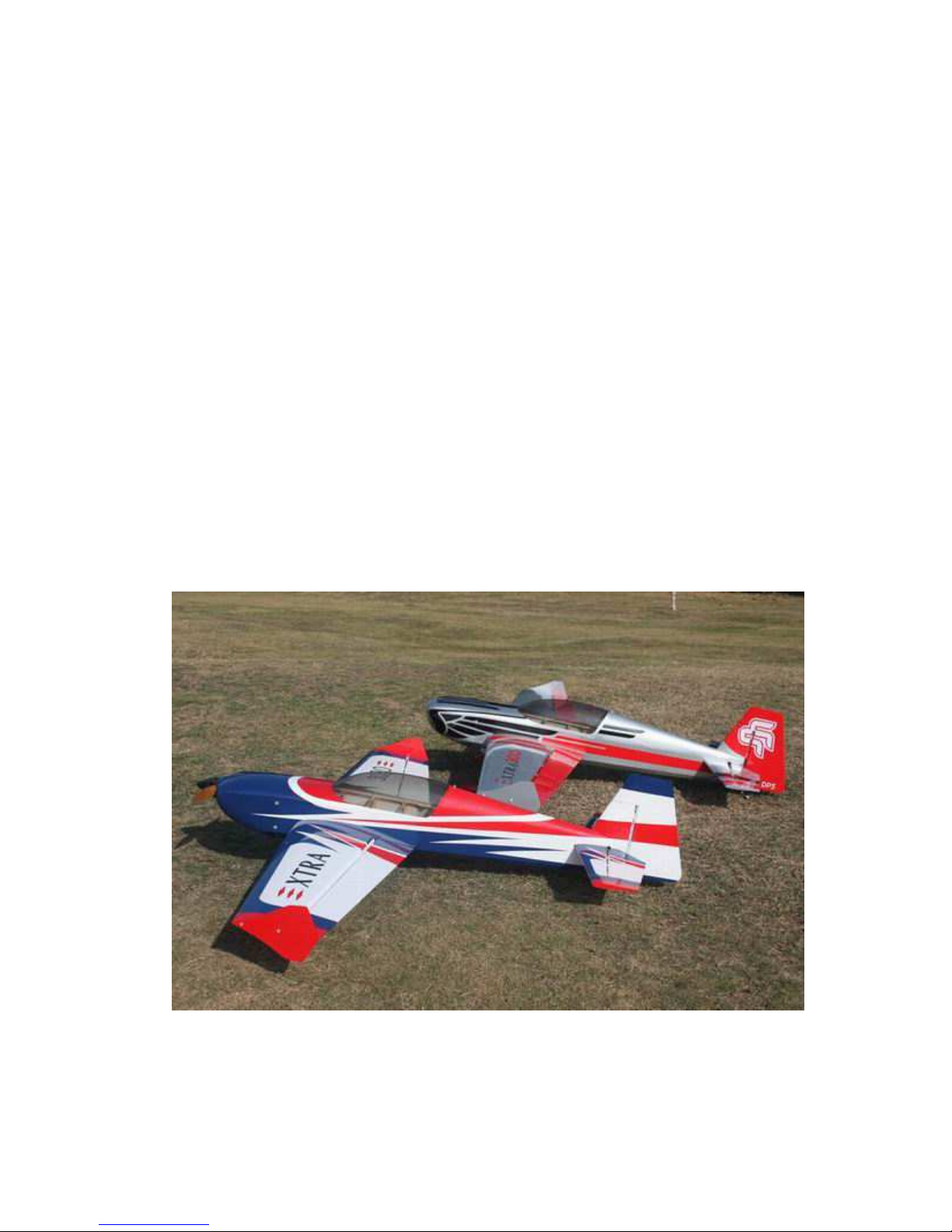
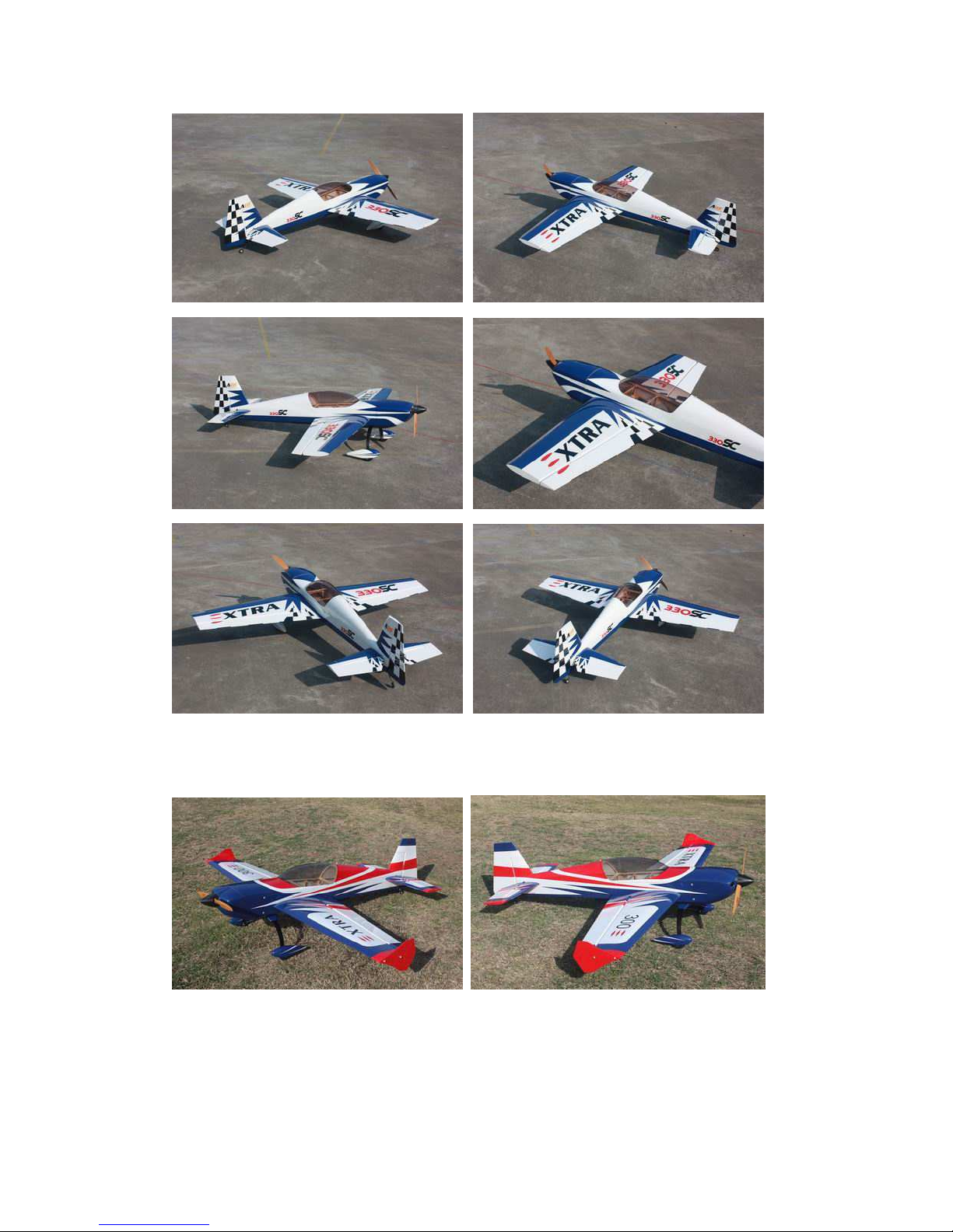
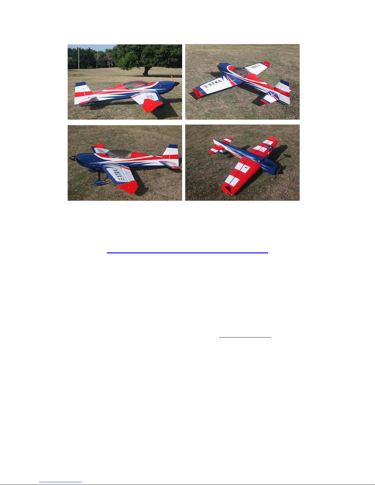
Thanks for purchasing this newly designed EXTRA300 aerobatic RC airplane. This
plane is to be powered by brushless motor, nitro and gas engine. Its weight is about
8.5 bs. It’s good for imac and free flight. It’s a beautiful plane with amazing flight
performance. It’s covered with genuine monocote, and comes with good quality
accessories, including carbon fiber wing tube, carbon fiber or Anodized 6061
Aluminum landing gear as an option. We hope you like this plane.
The new V2 version of EXTRA 20CC has the following Improvements than
V1 Previous versions:
1. This model has been designed for use with the latest generation of electric motor
and gas engine.
2.Control services is larger than V1 version. Up to 50 degrees of throw on all control
surfaces. Best for more vibrant aerobatic flight.
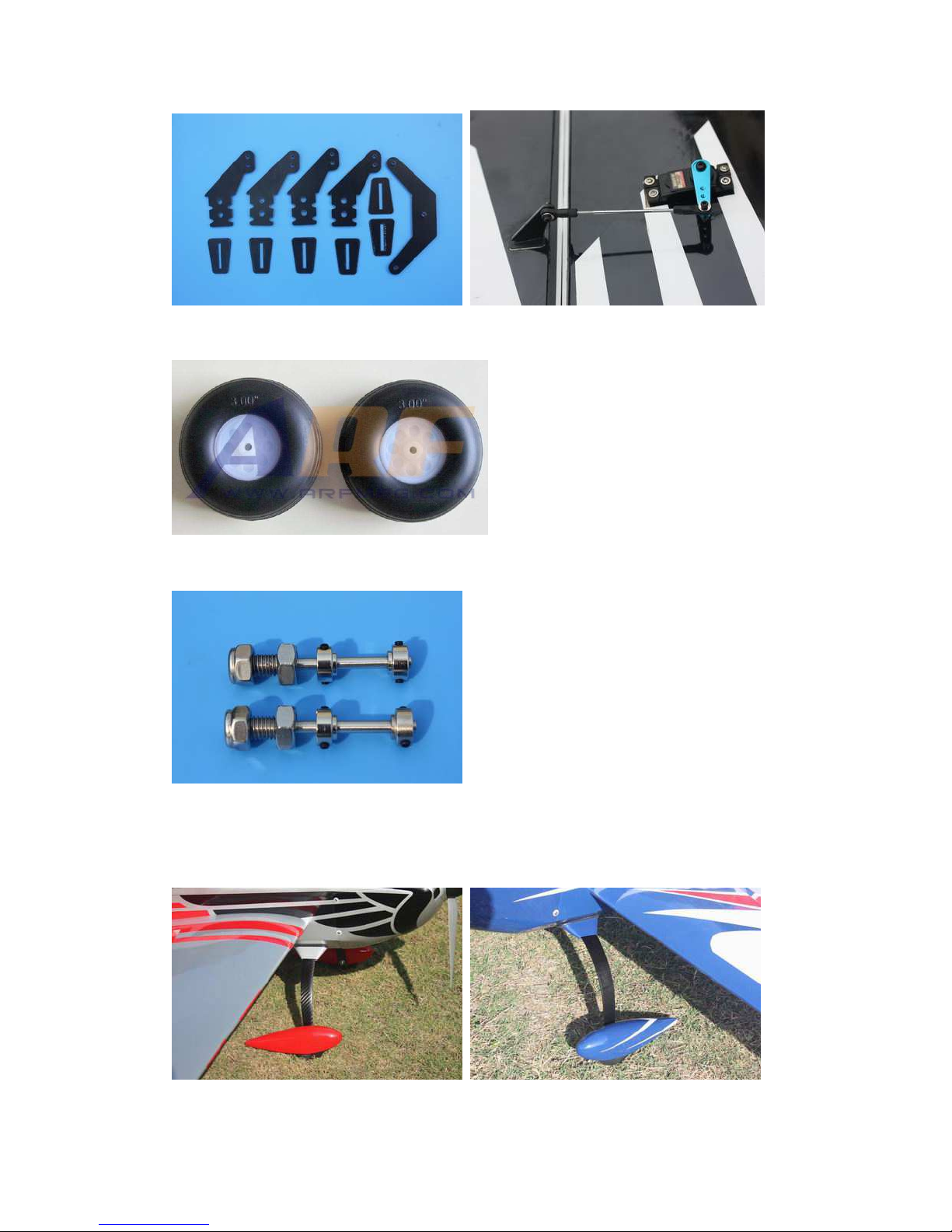
3.Improved wheels with more durable materials, and filled with rubber.
4.Using high quality cap head screws.
5.Improved ball link assembly.
6. Improved new Axle.the material of Axle is stainless steel .
7. Improved new Fiberglass horn assembly
8.Improved new C.F.Tail wheel assembly
9.Flat nylon hinges for better flying strength
10. Include Side Force Generator’s(SFG)
11. Air exit opeing behind the rudder servo for electric set-ups.
12. This V2 new design with a longer fuselage moment arm aids the tracking of the
model, giving it rock sold precision flight. Making it perfect for modern day flight
schedules for IMAC and Freestyle competitions.
A QUICK WORD ABOUT SAFETY AND RADIO
CONTROL FLYING MODELS
With radio control aircraft, like any hobby or sport, there are certain risks. The operator of
these models is responsible for these risks. If misused or abused, you may cause serious bodily
injury and/or damage to property. With this in mind, you will want to be certain that you build
your model carefully and correctly. If you are not an experienced flier, have your work checked
and ask for help in learning to fly safely. This model aircraft is not a toy and must be operated
and flown in a safe manner at all times. Always perform a pre-flight check of the model
including all control surfaces, proper function of the radio gear, structure, radio range, and any
other area relating to the safe operation of this aircraft.
Models are not insurable but operators are. You can obtain coverage through membership in

the Academy of Model Aeronautics (AMA). For an AMA information package call
1-800-435-9262, ext. 292 or visit the AMA website at "www.modelaircraft.org".
By the act of using the final assembled model, the
purchaser/operator accepts all resulting liability.
ARF MODELS WARRANTY AND RETURN POLICY
We guarantee that the plane is in perfect condition at purchase. The warranty
will be voided after modifications and usages. If you have any questions or find any
issues, please contact the distributors in your area.
SPECIFICATIONS
Wing Span: 67-1/2"(1715mm)
ength: 66"(1680mm)
Wing Area: 927sq in(59.8sq .dm.)
Flying Weight: 8-8.8lbs(3600-4000g)
Engine:.70-.91(2C) .91-.110(4C) 20-26cc gas
Electric Power:
KUZA EXM4130 KV350 with 6S 3800-44000mAh 17x8 or 18x8 prop
KUZA EXM4130 KV280 with 8S 3300-37000mAh 17x8 or 18x8 prop
Hacker A50-16S with 6S 3800-44000mAh 17x8 or 18x8 prop
DUSKY XM5060EA-470KV
with 6S 3700-4400 mAh 17x8 prop
Or other 1500-1800Watt electric motor
ESC:80-100A
RADIO:4CH/4-6S

Features:
Newly designed structure
Two pieces removable wings
Aerofoil tail wings
PVC canopy
Power by Electric motor & Gas engine
arger aileron and elevator design for excellent 3D aerobatic flying
The air exit for the electric set up still needs to be inside the fuselage behind the
rudder tray.
Include Side Force Generator’s(SFG)
Servo extension safety connector clips

High performance cap head screws
Flat nylon hinges for better flying strength
High quality 2.5mm ball links assemblys
New Fiberglass horn assembly

High-quality durable rubber wheels
Improved new Axle (the material of Axle is stainless steel )
Two options for landing gear: Anodized 6061 Aluminum or Carbon fiber
Carbon fiber landing gear 6061 Aluminum landing gea

New Carbon fiber tail wheel assembly
Carbon fiber wing tube
Canopy extended into cowl
Quick release canopy latch

Honeycomb Board carton packing for safer transportation
Scheme A Silvery/red/black
Scheme B White/blue/black

Scheme C White/blue/red

Items Required to Complete This Model:
• 1500-1800Watt electric Motor or
20-26CC Gas
• Appropriate propeller for your
Motor
• All required engine and exhaust
mounting hardware
• Ignition battery and switch
• One quality throttle servo and
appropriate servo arm
• 3-4 Pcs
high quality metal gear servos or
better for the ailerons and elevators
• Appropriate servo arms for the above
•
Servo wire extensions. recommends five
12”
•
Two switches with charging jacks for
the Rx
• Two high quality Rx batteries of
significant capacity to power your
choice of servos.
• One Receiver of your choice
Shop Supplies/Tools
• Covering Iron and heat gun
•
Assortment normal hobby tools such as
screwdrivers, hobby knife, drill and
drill bits, pliers, etc.
• Thick and Thin CA adhesives
• 30 minute Epoxy
• Isopropyl alcohol
• Ruler or tape measure
• Blue thread-lock or equivalent
•

Note: As with all kits, it’s a ood idea to read all the instructions
and study the parts before you be in construction. Handle the parts
of this kit with care so you do not dama e any of the structure or
coverin . Inspect all the parts for any shippin dama e and report
any issues to as soon as you can. Make sure you have a flat and
sturdy workbench and follow all safety advice for the tools and
adhesives you plan to use.
AIRCRAFT COVERING
1. With all ARFs, varying temperatures and storage delays can cause covering
material to loosen over time and transportation. recommends lightly going over all
the covering with a covering iron set at medium temperatures. Be sure to use a
soft cover over your iron so you do not scratch the covering surface. Be sure you
go over all seams and edges of the covering to assure it is secure to the airframe
and other covering. Be careful not to apply too much heat or you may cause
bubbles or damage to the covering. A heat gun may also be used along with a
soft cotton cloth to shrink and adhere the covering. Again, be extremely careful
when using a heat gun.
2. Be sure to seal any exposed wood with a thin coating of epoxy to prevent engine
oil from soaking in. This is especially important around the engine compartment
and servo openings with exposed areas.
3. Some modelers prefer to seal the hinge gaps using strips of appropriate covering
or clear trim tape. We have found this to be helpful with models intended for
higher speed flight or models with unusually large hinge gaps. aircraft utilize a
very tight double beveled hinge line and do not normally require this step.
Sealing the hinge gaps is therefore left as an option for the modeler.

Please verify the accessories before assemble:
Fiber glass servo horns: 4 single horns for ailerons and elevator. 1 dual horns for
rudder.
There is a layer of protection film on the horns. Please remove the film as shown
following picture.
Make sure to sand the horns to keep its strength.
Pushrods: Two 2.5x60mm for aileron. Two 2.5x110mm for elevator (you have option
to use one or two servos).

Ball links: 8 for aileron and elevator.
Pull-pull setup for the rudder.
5 Servo extension safety connector clips
New Carbon fiber tail wheel assembly

Screews for landing gear: 4(4x20mm) Hexagon bolts & 4mm stainless steel
Self-locking nuts & washers
Screews & Washers for cowl
: 4(2.5x12mm) Hexagon socket screws
& 4 PTFE Washers
4 Hexagon socket screw wrenches

Motor mount for brushless motor
Engine mount for nitro and gas engine
Win Assembly
NOTE: There are pictures of different planes in this manual, however, this plane’s
wings is assembled the same way.
1. It is much easier to install the twin control horns before installing the wing.
ocate the fiberglass aileron control horns, ball links, and associated bolts and
nylon-insert lock nuts. Use some fine sandpaper to roughen up the center areas of
the two control horns so that the glue adheres better. Using a sharp hobby knife cut
the covering away from the slots in the rudder and trial fit the control horns.
2. Mix up some 30 minute epoxy and coat the inside of the slots and the center of
the control horns. Hint: a scrap piece of 1/16” ply, tooth pick, or old hobby blade
can be used to coat the inside of the aileron slots. Slide the control horns in place
and make sure they are centered perfectly by using a ruler to measure between the
pivot holes and the hinge line. Wipe any excess glue off with isopropyl alcohol and
paper towels. Install the ball links, bolts and nuts into the holes to help assure
alignment of both control horns while the glue cures. Set aside until cured.

3. The slots for the supplied hinges are pre cut. ocate the hinges and dry fit the
hinges and aileron into place and test the operation. The hinges should seat fully
into the slots so that the hinge line gap is minimal while still allowing full aileron
deflection.
4. Before gluing the hinges in you must first clean the hinges of any mold release
agent using isopropyl alcohol. also recommends scuffing up the plastic with light
sandpaper for maximum glue adhesion.
5. Mix up some 30 minute epoxy and using a toothpick or small wooden dowel coat
the inside of each hinge slot with epoxy. Also put a thin layer of epoxy on one side
of the hinges. Install this end into the slots of the rudder and make sure each hinge is
properly aligned at exactly 90 degrees to the hinge line.
6. Now coat the other end of the hinges with epoxy and install the aileron into the
trailing edge of the wing. Again, make sure the hinges remain in proper alignment.
Using paper towels and some isopropyl alcohol clean off any excess epoxy from the
hinges and surrounding areas.
7.Make sure the aileron is fully seated so that the hinge gap is minimal while still
allowing full deflection of the aileron. When satisfied, use some masking tape to
hold the aileron in place along the bottom and counterbalance. After the epoxy has
cured, remove the masking tape and check for proper operation. If the hinges are
dry some light oil carefully placed on each hinge will help greatly.

8. Cut the covering from the aileron servo slots from corner to corner and iron down
inside the openings. Connect servo wire extensions to your servos and secure the
connections with the supplied clips. Feed the servo wires into the wing and out the
root. The screw holes for servo mounting are laser pre-drilled, it is advisable to
apply some thin CA to strengthen them, Install the servos and screw firmly in place.
9. Use your radio to set the centers of each servo and then assemble and adjust the
length of each control rod. The servo arm should be as close to perpendicular to the
control rod as possible while the aileron is at neutral. Double check all screws, bolts
and nuts to assure proper installation and operation without binding.Once satisfied,
permanently attach the ball link to the servo arm with the supplied screw and nut.
10.Check the final radio operation of the ailerons and make sure there is no binding or
servo fighting of each other. Also check to make sure all linkage bolts and nuts are
secure.

(Below long A U arm is not included)
Elevator Assembly
NOTE: There are pictures of different planes in this manual, however, this plane’s
elevators is assembled the same way.
1.Cut the covering over the hole for elevator on the fuselage. Glue the elevator to the
fuselage. Make sue it’s centered.
2,Glue the hinge for the elevator the same way as the main wings.

3.Install the horns the same way as the horns on the aileron. Use your radio to set
the servo center position and install the large control horn onto the servo.
Assemble the control rod and ball links and adjust the control linkage for proper
geometry. When satisfied, screw the ball link to the servo arm. The servo arm
should be as close to perpendicular to the control rod as possible while the
elevator is at neutral. Double check all screws, bolts and nuts to assure proper
installation and operation without binding.
(Below long A U arm is not included)
4.To install the horizontal stabilizers you first need to install two 12” servo wire
extensions in the fuselage so that they extend from the radio compartment to the aft
openings.
5.There is an option to use one servo or two servos for the elevator. If using one
servo, the 2 parts of the elevator need to be connected by the Fiber glass block with

glue as shown below. The picture is for illustration only. Actually, the connection of
the 2 parts needs to be performed in the fuselage after the hinges are connected.
Tail Wheel Installation
1. Start tail wheel assembly installation.For safety, please remove all screws and
then re-assemble with thread locker.
2. Drill 2 mm holes on the bottom rear of the fuselage, secure the tailwheel bracket
with the provided screws. For best results, the pivot point of the assembly should
be over the hinge line of the rudder.
Table of contents
Other arf Toy manuals

arf
arf SLICK540 120E User manual

arf
arf PA-20 Pacer 10e User manual

arf
arf 70 Series User manual

arf
arf AT.6-TEXAN Owner's manual

arf
arf AVENSIS Owner's manual

arf
arf Composite QQ Yak 54 2.6 m User manual

arf
arf XPower P-51D MUSTANG User manual

arf
arf YAK 55M User manual

arf
arf MINIMOA GLIDER User manual

arf
arf Katana User manual
Popular Toy manuals by other brands

PSI Woodworking Products
PSI Woodworking Products PKYOYO manual

Blizzard
Blizzard D.VA'S MEKA Building instructions

Fisher-Price
Fisher-Price J2462 instructions

Aviation Design
Aviation Design super scorpion Assembly manual

Pai Technology
Pai Technology Botzees Go! Dino instruction manual

KidKraft
KidKraft 53409 Assembly