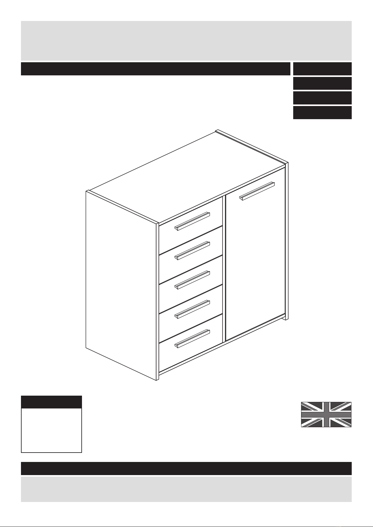
Argos New Sywell 259/1892 User manual
Other Argos Indoor Furnishing manuals

Argos
Argos 338/7005 User manual

Argos
Argos Hygena Charlie 323/2349 User manual

Argos
Argos Java 156/5465 User manual

Argos
Argos Kensington 424/7429 User manual

Argos
Argos Aspley 481/9651 User manual

Argos
Argos 709/2592 User manual

Argos
Argos PAULO 1442966 User manual

Argos
Argos Allura 7357103 User manual

Argos
Argos 166/6890 User manual

Argos
Argos 496/1932 User manual

Argos
Argos Montana 395/7370 User manual

Argos
Argos Normandy 428/2611 User manual

Argos
Argos 2 Door 3 Drawer Sideboard User manual

Argos
Argos 033 3042 Series User manual

Argos
Argos SCHREIBER 6324852 User manual

Argos
Argos Ohio Ottoman Coffee Table Ottoman 143/6563 User manual

Argos
Argos Zest 245/7558 User manual

Argos
Argos Aspley 459/1261 User manual

Argos
Argos HOME Maine 2 Door 1 Drawer Sideboard User manual

Argos
Argos Marlow 424/1195 User manual


Popular Indoor Furnishing manuals by other brands


Coaster
Coaster 4799N Assembly instructions

Stor-It-All
Stor-It-All WS39MP Assembly/installation instructions

Lexicon
Lexicon 194840161868 Assembly instruction

Next
Next AMELIA NEW 462947 Assembly instructions

impekk
impekk Manual II Assembly And Instructions

Elements
Elements Ember Nightstand CEB700NSE Assembly instructions