ARRI TRINITY 2 User manual
TRINITY 2 Setup
Q U I C K G U I D E
01.09.2022
TRINITY 2 assembly quick guide 2
1 TRINITY 2 assembly quick guide
Preperations
ADVICE
Always ensure that you are using a proper C-Stand, Low Boy Stand
or an another suitable stand.
Make sure the stand is set up on even ground.
Make sure you are not exposed to strong wind or heavy rain.
Securing the stand with sand bags.
Make sure that the Yoke of the Docking Bracket is placed above
the longest leg of the stand.
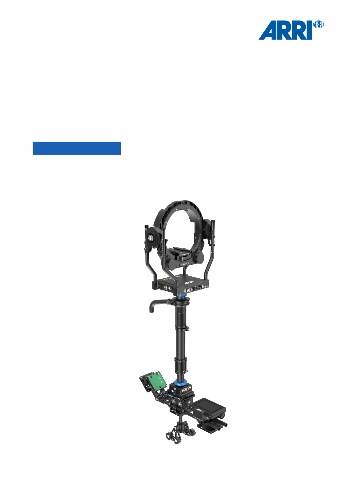
Mount the Top Stage TST-2
► Bring the top stage close to the bottom of the inner post.
► Locate the red dot on the main cable plug and socket.
► When both marks are aligned, insert the LEMO 3B plug
into the socket.
► Turn the blue docking ring with your fingers until the thread fully en-
gages.
► Use the Post Tool (K2.0040046) to finally tighten the Docking Ring.
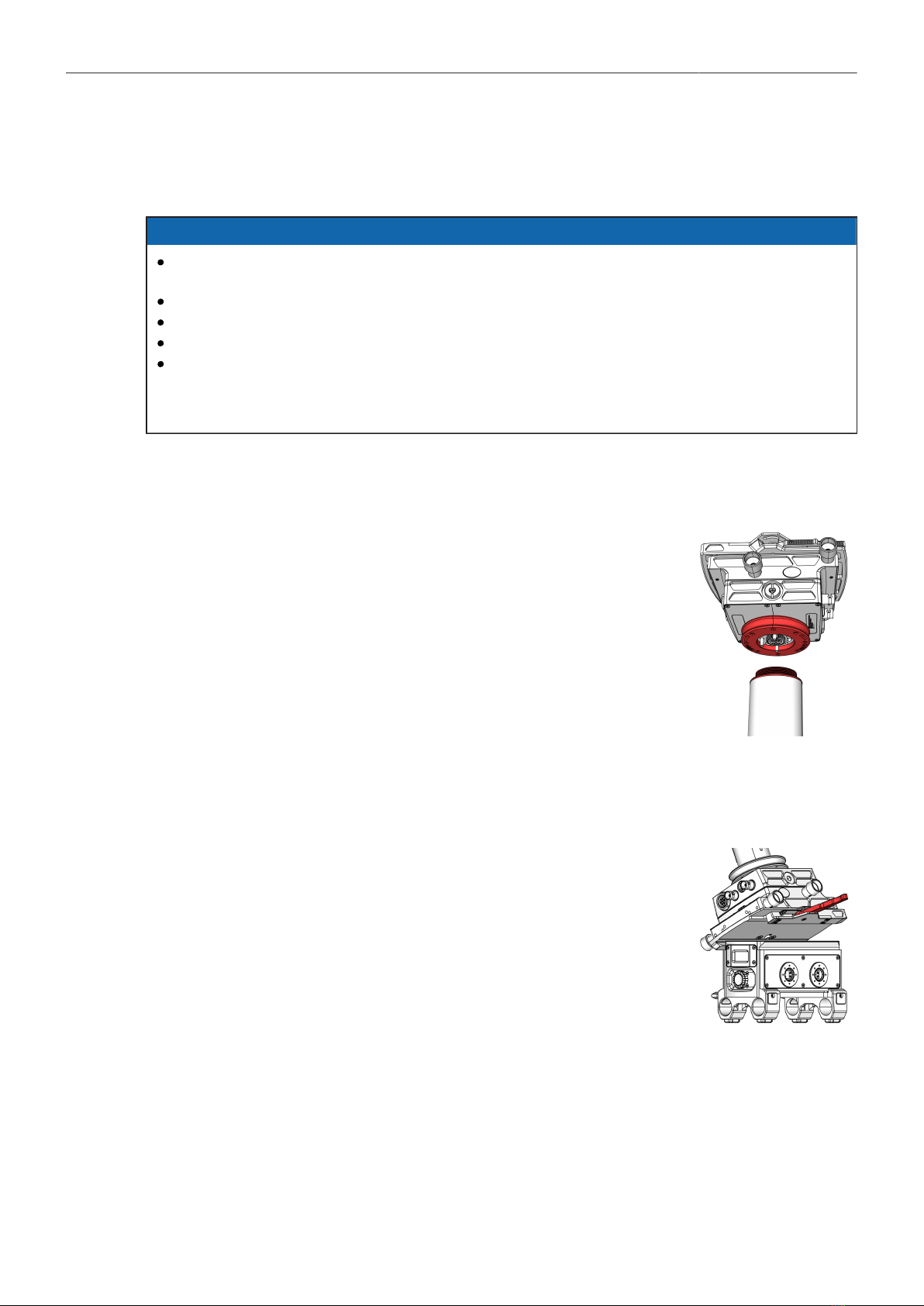
Mount the Batteryhanger BHM-2 to the Top Stage TST-2
► Unlock and open the Top Stage clamp mechanism.
► Align the Battery Hanger Module dovetail with the Top / Bottom Stage
mount.
► Lift the Battery Hanger Module completely into the Top / Bottom Stage.
► Lock the dovetail clamp mechanism.

TRINITY 2 assembly quick guide 3
Install the 1.8in Gimbal to the Center Post
► Use the Post Tool (K2.0040046) to open the centering ring by turning it
to the left.
► Open the gimbal clamp lever.
► Place the Gimbal onto the Post
► Tighten carefully the center ring.
Do not overtighen the center ring!
► Move the gimbal to the desired position by rotating and sliding the gim-
bal.
► Lock the clamp lever. → The Gimbal is positioned.
Attach the TRINITY 2 head to the upper Post
► Bring the TRINITY 2 head close to the upper end of the post.
► Ensure that the bubble at the back of the TRINITY head is pointing in
the same direction as the bubble at the Top Stage.
► Locate the red dot on the main cable plug and socket.
► When both marks are aligned, insert the LEMO 3B plug
into the socket.
► Turn the blue docking ring with your fingers until the thread fully en-
gages.
► Use the Post Tool (K2.0040046) to finally tighten the Docking Ring.

TRINITY 2 assembly quick guide 4
Place the TRINITY 2 system into the Docking Bracket
► Pusch the Balance Rod fully back first.
► Lift the rig into the Docking Bracket and slide the post into the park posi-
tion.
Add the 19mm Rods to the Batteryhanger BHM-2
► Turn both Rod Clamp wing nuts to the left to open the clamp mecha-
nism.
► Insert the desired 19mm rods with the already mounted hinge at the
back.
► Tighten both rod clamp wing nuts.
ATTENTION
Do not over tighten, when using carbon fiber rods.

TRINITY 2 assembly quick guide 5
Complete the Battery Hanger / Sled
► Attach one battery mount to the rear hinge and the second battery
mount to the bottom front bars.
► Attach the RCP-3 on top of the bars in front.
► Attach the pendulum to the 19mm rods in the center under the battery
holder.
► Tighten all clamp wing nuts.
ATTENTION
Do not over tighten, when using carbon fiber rods.
► Connect the Power Cable, BHM-2 to TST (K2.0037771).
► Connect the Battery mounts to the Battery Hanger.
► Connect the RCP-3 to the Top Stage using the RCP-3
FS Can Bus Cable (K2.0043883).
Mount the Master Grip TRINITY
► Before you begin, make sure the gimbal handle extension is attached to
the Gimbal handle.
► Open the clamp lever of the Mounting Bracket.
► Place the Master Grip TRINITY on the gimbal grip as close as possible
to the bend.
► When you have reached the desired position, tighten the clamp wing
nut.
Mount the Monitor to the Master Grip TRINITY
► Loosen the mounting bracket clamp lever.
► Slide the 19mm rod into the insert.

TRINITY 2 assembly quick guide 6
Mount the Monitor Adapter to the Master Grip TRINITY
► There are two different monitor adapters to choose from: Monitor
Adapter for Transvideo (K2.0014831)
Monitor Adapter for Small HD (K2.0014832).
► Slide the monitor adapter on the 19mm rod and bring it in the desired
position.
► Tighten the clamp.
Mounting the Transvideo Starlite Monitor
► Remove the location pins first.
► Place the monitor and bring it in the desired angle.
► Tighten the screw at the back.
Mounting the Small HD 503 Monitor
► Place the monitor.
► Bring it in the desired angle.
► Tighten the screw at the back.

TRINITY 2 assembly quick guide 7
Wiring Master Grip TRINITY
► Connect the MTG Monitor Pwr, Lemo 0B, 5pin (K2.0038999) with the
Transvideo / ARRI Starlite monitor and with the upper LBUS Socket
at the
Master Grip TRINITY.
► Or connect the MTG Monitor Pwr, Lemo 0B, 2pin (K2.0038998) with the
SmallHD monitor and with the
upper LBUS Socket at the Master Grip TRINITY.
► Connect the TRINITY 2 Joystick Cable 75cm/29.5in (K2.0043861) with
the lower LBUS Socket at the Master Grip TRINITY and with the LBUS
Socket at the
TRINITY 2 head.
► Connect the 12G HD SDI BNC Cable, 0,63m/25in (K2.0041984) with
the Monitor Out at the TRINITY 2 head and the Video In of the monitor.

TRINITY 2 camera setup quick guide 8
2 TRINITY 2 camera setup quick guide
Foreword
ADVICE
Only a precisely executed camera preparation will enable you to get the TRINITY 2 system in perfect
SYMMETRY and NEUTRAL BALANCE.
Balance Strategy
The camera preparation must meet the following requirements:
ADVICE
Compact length and low Center Of Gravity (COG)
Keep the COG (centre of gravity) of the TRINITY 2 head as low as possible and the overall
length of the camera setup should be as compact as possible.
If the camera length is unnecessarily long, the COG / hight of the Tilt axis of the TRINITY 2 head
could be quite high, which will force you to extend the Center Post to compensate for top weight.
As the Center Post lengthens the more extreme the degree of inertia will be and will reduce the
agility of the TRINITY 2.
When using an ALEXA 35 or ALEXA Mini LF, Signature Prime lenses or a zoom lens keeps the
camera setup at an optimal length.
If the ARRI ALEXA LF or AMIRA is being used a Prime Lens will be required.
Most box-type television cameras with a zoom lens do have the right length for use with the
TRINITY 2 system.
Video Transmitters should be mounted to the rear Battery Hanger.
This uses the weight of the transmitter as a counterweight and the total weight of the system can
be kept low.
Camera Preparation
The camera preparation must meet the following requirements:
ADVICE
Camera components and accessories mounted on the camera must be attached symmetrically
and matched to each other.
If two focus motors are needed, use two 15mm rods (equal length and same material) and mount
them on the top of the camera.
Now place one focus motor on each rod.
Make sure that the gears are facing the front of the lens and the motor housing of the camera
body.
If only one focus motor is required, then two rods are also required.
Place the focus motors vertical above the lens.

TRINITY 2 camera setup quick guide 9
Secure component and accessory attachment
ADVICE
Make sure that all components of the camera and accessories in the setup are fully tightened.
Ensure that none of the components are loose or have any play to avoid vibration and any
performance issues.
Camera Dovetail Plates
Using the SAM plates will speed up the camera setup and later the balancing
process.
The special hight of every SAM plate will lift the dedicated camera right into the
center of the TRINITY 2 inner ring.
This way a perfect COG of the camera is guaranteed.
Available SAM plates and lens support brackets:
K2.0041201 Stabilizer Adapter Mount SAM-Zero
K2.0018851 Stabilizer Adapter Mount SAM-1 for ALEXA
K2.0014215 Stabilizer Adapter Mount SAM-2 for ALEXA
KK.0016116 Stabilizer Adapter Mount SAM-2 Set for ALEXA Mini
K2.0014630 Stabilizer Adapter Mount SAM-3 Set for AMIRA
K2.0024508 Stabilizer Adapter Mount SAM-6
K2.0039405 Stabilizer Adapter Mount SAM-6 450mm/18in
K2.0034512 CSS Broadcast Dovetail Plate (SAM plate standard width)
K2.0039803 Stabilizer Plate for CBP 355mm/14in
K2.0038536 Stabilizer Plate for CBP 450mm/18in
K2.0033662 Stabilizer Adapter Mount SAM-4
KK.0038971 Long Stabilizer Mount 15mm Mini/Mini
KK.0038972 Long Stabilizer Mount 19mm Mini/Mini LF
K2.0039089 Compact Lens Support CLS-1
K2.0040036 Balance Utility Dovetail BUD-2
K2.0039861 Dovetail Utility Base DUB-1
K2.0038537 Stabilizer System Bracket SSB-2 19mm
K2.0038618 Stabilizer System Bracket SSB-2 15mm
TRINITY 2 camera setup quick guide 10
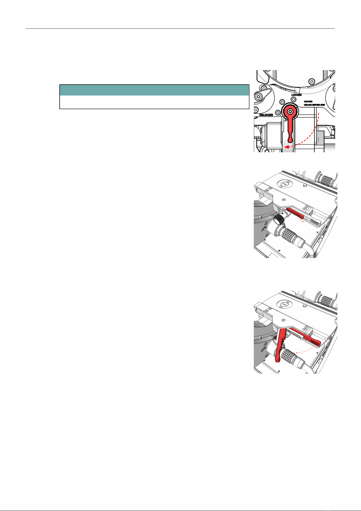
Prepare the TRINITY 2 Head
ATTENTION
Ensure that the Stabilizer is switched OFF.
Tilt-Lock
► Move the Lock lever to the left in the Locked position.
Safety Latch
► Touch the safety latch with your thumb and slide it fully to the right.
Clamp Lever
► Place your index finger behind the clamping lever and pull the
clamping lever forward until it reaches the end stop on the left
side.
Other manuals for TRINITY 2
1
Table of contents
Other ARRI Camera Accessories manuals


Popular Camera Accessories manuals by other brands

Viltrox
Viltrox EF-NEX Mount instructions

Calumet
Calumet 7100 Series CK7114 operating instructions

Ropox
Ropox 4Single Series User manual and installation instructions

Cambo
Cambo Wide DS Digital Series Main operating instructions

Samsung
Samsung SHG-120 Specification sheet

Ryobi
Ryobi BPL-1820 Owner's operating manual


