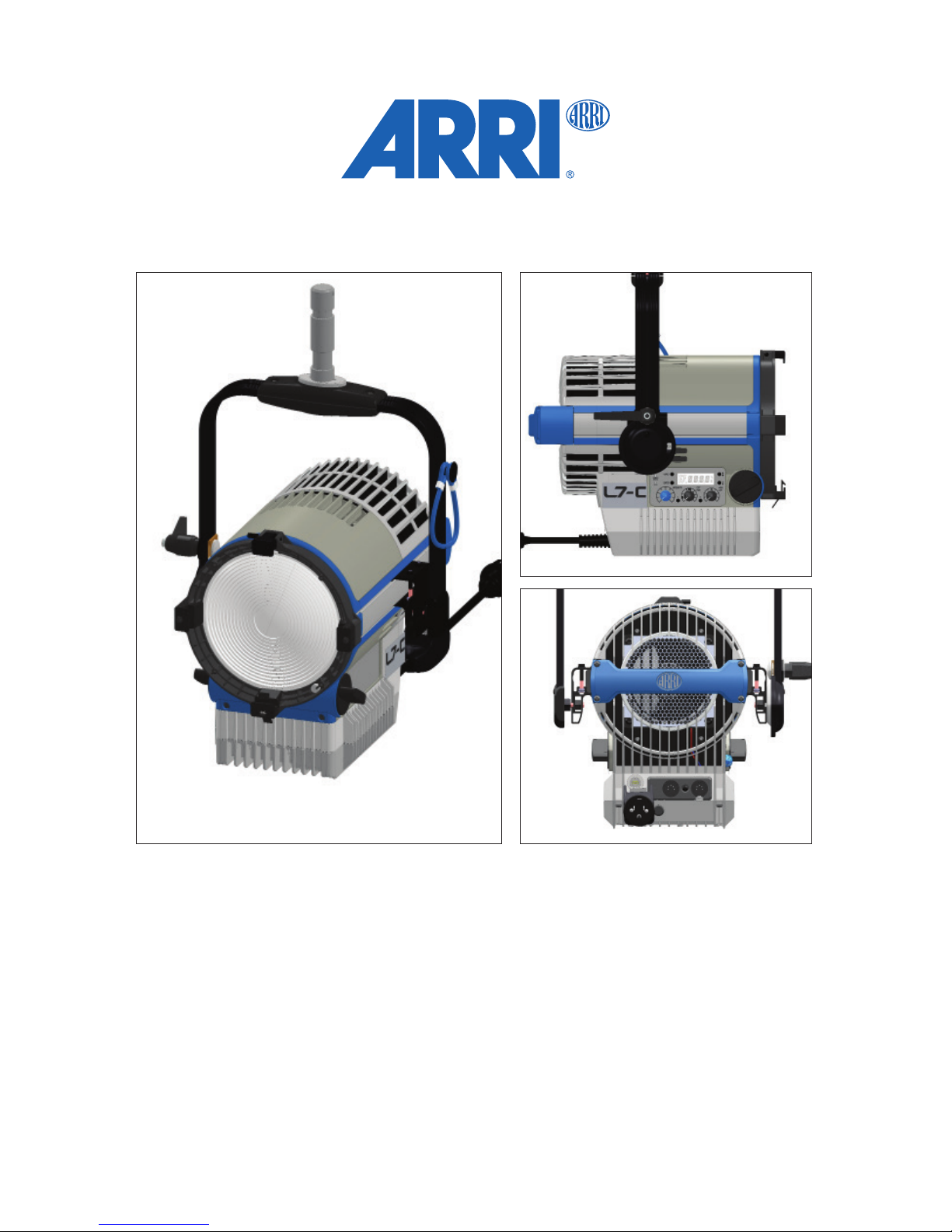
1.2 Description and features of your Lamphead
The L7 range lampheads are equipped with an electronically controlled LED light source. You can use them like a conventional
tungsten Fresnel xture but with far higher energy efciency. The newly developed optical system offers a continuous
focus range of 15-50° half peak angle and real 'Fresnel' characteristics: an extremely uniform light eld and clean shadow
rendition. The various types of L-series produce white or colored light with adjustable color temperature and green / magenta satu-
ration. For more information, see "Specications" on page 26. The light spectrum has been specically designed for excellent color
rendition. All xtures can be controlled over USB interface, DMX 512 / RDM protocol or on-board control panel (if equipped).
1.2.1 Properties
■Focus
Versatility is the key element in traditional Fresnels, especially the ability to spot and ood the beam as needed. Whether it’s
a ood eld for a pullback shot or a tight spot for a bright highlight, the continuous focusability of the L7 performs
just as expected.
■Versatile beam characteristics
The L7 provides the same ability as conventional Fresnel lenses to cut set elements and shape the light eld
with barndoors and ags.
■Even light eld
Clear, dened shadows have traditionally been a trait only of single source tungsten and daylight xtures. ARRI L7 Fresnels
provide the same single shadow properties designers expect, delivering natural results.
■Vibrant colors, full-spectrum lighting
True-to-life color rendition is an outstanding feature of the L range, comparable to a full-spectrum tungsten source. The fully
tuneable White light of the L7 C can be adjusted for different skin tones, camera sensors and mixed-light environments. Full
gamut color mixing enables the rendition of all color shades, making color lters dispensible.
■Cool light beam
Like all LED light sources the L7 does not emitt infrared or UV radiation and thus no forward heat, making talent feel
comfortable in the light beam.
The ARRI L range combines all advantages of LED technology and the traditional Fresnel lens. It integrates seamlessly into esta-
blished working practices, so that designers can stick with their creative techniques and studios will have no need to change their
operating procedures.
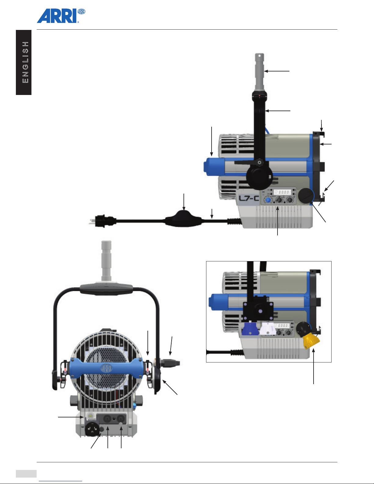
1.2.2 Product features
■Focus knob
True Blue-style focus knobs provide precise adjustment and rapid ood-to-spot with only three turns. Knobs on both sides of
the xture ensure easy access from all positions.
■Sliding stirrup
The sliding stirrup design enables precise compensation for front-end accessories.
■Yoke
With an extremely slim prole, the extruded aluminum yoke provides high strength without added weight. An optional pole-
operated yoke allows full operation of pan and tilt from the oor and is therefore a popular choice for many studios.
■Tilt lock
The high strength tilt lock provides extremely secure locking, eliminating movement and slippage and ensuring that the xtures
will stay where you put them.
■DMX control
All functions of the L7 are controllable through DMX. The L7 is also fully RDM compatible and is equipped with a feedback
channel for reporting all set parameters including system status and hours on the light engine.
■On-board control
For location applications the L7 is equipped with an on-board control for manual adjustment of intensity, color temperature and
plus/minus Green as well as hue and saturation (functions available depending on type).