manuals.online logo
Brands
  1. Home
  2. •
  3. Brands
  4. •
  5. ARRI
  6. •
  7. Lighting Equipment
  8. •
  9. ARRI X 2 User manual

ARRI X 2 User manual

1/2007
Bedienungsanleitung
Operating Instructions
Stand: 16.01.2007
as at: 16.01.2007
ARRI X 2
ARRI X 5
ARRI X 12
ARRI X 40/25
ARRI X 60
Arnold & Richter CineTechnik GmbH Co. Betriebs KG
Pulvermühle
D-83071 Stephanskirchen
Germany
Tel: (+49) 08036 3009-0
Fax: (+49) 08036 2471
Ident.No. L5.82401.0
1/5
Inhaltsverzeichnis:
Allgemeine Hinweise: Seite 2
Wichtige Sicherheitshinweise: Seite 2
Technische Daten: Seite 2
Warnung!Wärme- und UV-Emission: Seite 2
Produktbeschreibung: Seite 3
Allgemeine Bedienungshinweise: Seite 4
Sicherung des Scheinwerfers: Seite 4
Sicherheitseinrichtungen: Seite 4
Inbetriebnahme: Seite 4
Lampenwechsel / Einsetzen der Lampe: Seite 4
Einsetzen des Zubehörs: Seite 5
Wartung: Seite 5
Montage für Haltebügel: Seite 5
ARRI Service Werkstätten: Seite 5
Table of Contents:
Notes: Page 2
Important SafetyInstructions: Page 2
Technical Datas: Page 2
Warning!Heat and Ultra Violet Radiation Page 2
Product Description: Page 3
General Instructions: Page 4
Protection ofthe Lamphead: Page 4
Protective Devices: Page 4
Putting into Operation: Page 4
Lamp Exchange / Inserting the Lamp: Page 4
Installing Accessories: Page 5
Maintenance: Page 5
Stirrup Mounting Instruction: Page 5
ARRI Service Locations: Page 5
ARRI X 2; Id.-No.: L1.8205x.x
ARRI X 5; Id.-No.: L1.8220x.x
ARRI X 12; Id.-No.: L1.8225x.x
ARRI X 40/25; Id.-No.: L1.824xx.x
ARRI X 60; Id.-No.: L1.8265x.x
2/ 5
Allgemeine Hinweise:
•Lesen Sie diese Bedienungsanleitung sehr sorgfältig vor der
ersten Inbetriebnahme. Der folgende Text enthält wichtige
Hinweise für die Handhabung von ARRI Beleuchtungsgeräten.
•Beachten Sie in Ihremeigenen Interesse die Sicherheits- und
Warnhinweise.
•Bitte beachten Sie die Bedienungsanleitungen der
Vorschaltgeräte sowie die Bedienungsanleitung der
Lampenhersteller.
•Bitte beachten Sie auch die Montage für Haltebügel.
Wichtige Sicherheitshinweise:
•Vorsicht Hochspannung!Lebensgefahr!
Vor dem Lampenwechsel allpolig vom Netz trennen!
•Vorsicht heiße Lampe!
Lampe muß vor demWechseln ausreichend abgekühlt sein.
•Scheinwerfer nicht ohne Lampe einschalten!
•Schutzvorrichtungen dürfen nur zu Servicezwecken von Fach-
personal entfernt werden und sind anschließend sofort wieder
anzubringen.
•Der Sicherheitsschalter (14) darf in keinemFall überbrückt
werden.
•Scheinwerfer nicht ohne Doppel-Schutzglas und/oder Reflektor
betreiben.
•Achtung!Das Lampengehäuse kann hohe Temperaturen
annehmen. Beachten Sie die Werte in der Tabelle.
•Lüftungsschlitze dürfen nicht abgedeckt werden.
•Halten Sie die Anschlußkabel vomScheinwerfer fern.
•Direkte Bestrahlung anderer Scheinwerfer vermeiden. Gefahr
der Überhitzung.
•Beschädigte und durch Wärme verformte Lampen müssen
gewechselt werden.
•Wenn die Wirksamkeit der Doppelschutzgläser durch sichtbare
Beschädigung z.B: durch Sprünge und tiefe Kratzer
beeinträchtigt ist, müssen diese gewechselt werden. Der
Reflektor ist auszutauschen, wenn dieser matt wird oder eine
Deformation aufweist.
•Bei erkennbaren Schäden an Kabeln, Steckern oder der
Lampenhalterung darf der Scheinwerfer nicht in Betrieb
genommen werden. Wenden Sie sich an eine ARRI Service-
Werkstätte (siehe Werkstättennachweis auf Seite 5).
Notes:
•Please read the following operating instructions very carefully
before using this fixture for the first time. They contain
important information about operating ARRI-Lighting
equipment.
•For your own safety, please followall safety instructions and
warnings.
•Please also read the operating instructions of the ballasts and
the instructions of the lamp manufacturers..
•Please also note stirrup (yoke) mounting instruction.
Important SafetyInstructions:
•Caution high voltage!Danger!
Before replacing the lamp, disconnect lamphead from the
ballast.
•Caution!Lamp maybe hot!
Allowthe lamp to cool down sufficiently before replacing.
•Do not switch on the lamphead without a correct fitted lamp!
•Protection devices may not be removed except for service
purpose by qualified personnel, and must be reattached
immediately.
•Warning! Do not bridge protection switch (14).
•Do not switch on without double-protection glasses and/or
reflector.
•CAUTION!The housing of the lamphead can reach high
temperatures. Please refer to the attached table for maximal
values.
•Do not cover vent slots.
•Always keep the cables a reasonable distance away fromthe
housing.
•Do not directly illuminate other lampheads. Risk of overheating
or fire!
•The lamp shall be exchanged if it has become damaged or
thermally deformed.
•The double safety glass must be exchanged when they
become visibly damaged to such an extent that their
effectiveness is impaired, for exemple by cracks or deep
scratches. The reflector must be exchanged when it becomes
dull or deformed.
•Do not operate the lamphead if any damage to cables, plugs or
lampholder is detected. Please contact an ARRI-Service
location (refer to page 5 for contacts).
Technische Daten / Technical Data
Type
to
ta
Gewicht /
weight
ARRI X2 130°C 45°C 2,3 kg 0,3 m 1,5m (150cm) ± 90°
ARRI X5 130°C 45°C 7 kg 0,5 m 2,0m (200cm) ± 90°
ARRI X12 180°C 45°C 12 kg 1,0 m 3,5m (350cm) ± 90°
ARRI X40/25 200°C 45°C 18 kg 1,0 m 4,0m (400cm) ± 90°
ARRI X60 180°C 45°C 32 kg 1,5 m 4,0m (400cm) ± 90°
Nomenklatur / Technical Terms
to= maximale äußere Leuchtentemperatur im Beharrungszustand / maximum surface temperature
ta= maximale Umgebungstemperatur / maximum ambient temperature
= minimaler Abstand zu brennbaren Werkstoffen / minimum distance to flammable objects
= minimaler Abstand zu angestrahlten Flächen / minimum distance to illuminated areas
= Schwenkbereich / tilting range
WARNUNG!WÄRME– UND UV-EMISSION:
•Betreiben Sie den Scheinwerfer nur mit geschlossenemGehäuse
und wenn beide Schutzgläser unbeschädigt sind.
•Schauen Sie während des Betriebs niemals direkt in den
Scheinwerfer.
•Halten Sie den in der Tabelle festgelegten Mindestabstand zu
angestrahlten Flächen bzw. zu brennbaren Objekten ein.
•Der Betrieb des Scheinwerfers bei einemkürzeren Abstand zu
angestrahlten Flächen laut Tabelle kann Schädigungen der Haut
sowie der Augen verursachen.
WARNING!HEATAND ULTRAVIOLET RADIATION:
•Do not operate without complete lamp enclosure in place or
when protection glass is damaged.
•Do not stare directly at lamp in operation.
•Do not operate closer than the values mentioned in the table
to illuminated areas or to flammable objects.
•Operation at distances closer than the above mentioned
values may be harmful to eyes and skin.
3 / 5
Produktbeschreibung:
•Die Scheinwerfer der ARRI XReihe sind Tageslicht –
Scheinwerfer, die nach den neuesten Erkenntnissen der
Lichttechnologie für den professionellen Gebrauch nach IEC
60598-2-17 entwickelt wurden.
Der große Streuwinkel in Verbindung mit einer gleichmäßigen
Ausleuchtung und die robuste Bauweise ermöglichen den
universellen Einsatz imStudio wie auch bei Außenaufnahmen.
•Bei demKombinationsgerät ARRI X40/25 kann die
Lampenhöhe einfach über ein Verstellrad (7) mit Farbkenn-
zeichnung eingestellt werden.
•Auswechselbare Reflektoren erlauben eine große Variation
von Lichtstimmungen.
•Alle Bedienelemente sind übersichtlich und leicht zugänglich
angeordnet.
•ZumLampenwechsel ist nur ein Klemmhebel (6) zu betätigen
und die Lampe kann entnommen werden.
•Ein Schnellverschluß ermöglicht den raschen Austausch von
Zubehör und Entfernen der Doppel-Schutzscheiben zum
Lampenwechsel.
•Das Typenschild (12) ist seitlich amScheinwerfer angebracht
und enthält alle erforderlichen technischen Daten.
Bild 1 / picture 1
Bild 2 / picture 2
Product Description:
•The luminaries of the ARRI Xrange are daylight lampheads,
developed by computer aided design, provided with the latest
lighting technology and conformto the International Standard
IEC 60598-2-17.
The large beamangle with a flat even light and the compact,
strong housing makes it ideal for professional studio and
location applications.
•The power combined device ARRI X40/25, has a color coded
wheel (7) to adjust the lamp length easily.
•Changeable reflectors give a wide variety of light applications.
•The positioning of the operating elements is clear, the
accessibility is easy.
•The unique ARRI lamp holder opens and locks easily using
the lamp lock lever (6).
•A quick release latch can be opened quickly for installations of
accessories and removal of the double-safety glass for
changing the bulb.
•The identification plate (12) is located at the side of the
housing and contains all necessary technical information.
Index:
1 Zweite Aufhängung
Safety chain/wire attachment
2 Lampe / Lamp
3 Torsicherung
Top Latch
4 Bügelhalterung
Stirrup / Yoke mounting bracket
5 Scheinwerferkabel
Cable
6 Klemmhebel (nicht bei ARRI X2)
Locking lever (not available for ARRI X2)
7 Höhenverstellung (nur ARRI X40/25)
Adjustment (only ARRI X40/25)
8 Doppelschutzglas
Double safety glass
9 Zubehörrahmen
Accessorie frame
10 EIN/Aus-Schalter / ON/OFF - switch
11 Betriebsstundenzähler ( Nicht bei ARRI X2)
Hour counter (Not available for ARRI X2)
12 Typenschild
Product identification plate
13 Schraube für Schutzglasrahmen
Screwfor protection glass frame
14 Sicherheitsschalter
Safety switch
3
10
7
2
6
4
9
11
1
13
8
5
12
14
4 / 5
Allgemeine Bedienungshinweise:
•Den Lampenkolben nicht mit bloßen Händen berühren.
Eingebrannte Fingerabdrücke verkürzen die
Lebensdauer der Lampe.
•Das Einsetzen der Lampe erfordert große Sorgfalt. Die
Kontaktflächen müssen trocken und frei von
Verunreinigungen sein.
•Der feste Sitz der Lampe imSockel ist nach jedem
Transport zu überprüfen.
•Verwenden Sie nur Originalersatzteile und
Originalzubehör.
Sicherung des Scheinwerfers und des Zubehörs:
•Bei hängendemBetrieb muß der Scheinwerfer wie
auch das Zubehör durch eine Sicherheitsaufhängung
gegen Herabfallen gesichert werden. Diese Sicher-
heitsaufhängung muß ausreichend dimensioniert und
darf nicht zu lang sein.
•Die Tragfähigkeit des Sicherungsseiles und der
Verbindungsglieder muß mindestens für das 10-fache
Gewicht des zu tragenden Scheinwerfersystems wie
auch des Zubehörs ausgelegt sein.
Sicherheitseinrichtungen:
•Schutzklasse I / IP23
•Doppelschutzglas
•Labyrinthförmiger Gehäuseaufbau
•Torsicherung
•Zweite Aufhängung
Inbetriebnahme:
•WICHTIG: Bitte beachten Sie die Bedienungsanleitung
des Vorschaltgerätes.
•Überprüfen Sie, ob die Lampe funktionsfähig ist.
Beschädigte Lampen dürfen nicht in Betrieb genommen
werden (s. hierzu Abschnitt „Lampenwechsel / Einsetzen
der Lampe“).
•Vergewissern Sie sich, daß das für den Anschluß
vorgesehene Vorschaltgerät ausgeschaltet ist.
•Verbinden Sie den Anschlußstecker des Scheinwerfers
mit der Ausgangsbuchse des Vorschaltgerätes.
•ZumEinschalten Scheinwerfer amEIN/AUS-Schalter
(10) auf ON oder Stellung I einschalten.
•IndemSie nun das Vorschaltgerät einschalten, wird der
Scheinwerfer in Betrieb genommen.
Lampenwechsel / Einsetzen der Lampe:
•Vorsicht!Hochspannung!Lebensgefahr!
•Vor Entfernung der Doppel-Schutzgläser, Scheinwerfer
allpolig vomNetz trennen.
•ACHTUNG - heiße Lampe. Vor demWechseln Lampe
ausreichend abkühlen lassen.
•Schnellverschluß (13) öffnen und Doppel-Schutzgläser
nach oben entnehmen.
•Klemmhebel (6) nach links bis zumAnschlag drücken.
•Lampe (2) vorsichtig amSockel nach oben aus der
Lampen-Halterung heben.
•Einzusetzende Lampe nur amSockel fassen
(Fingerabdrücke amGlaskolben brennen ein und
führen zur Verkürzung der Brenndauer).
Reinigungshinweise des Lampenherstellers beachten
•Lampe (2) vorsichtig bis zumAnschlag in Lampen-
halterung einsetzen, dabei muß die Typenbezeichnung
amSockel von vorne zu sehen sein.
•Klemmhebel (6) nach rechts bis zumAnschlag drücken.
•Nur Lampen in Scheinwerfer entsprechender Leistung
verwenden (Leistungsangabe beachten).
•Schnellverschluß schließen.
General Instructions:
•Do not touch the lamp quartz envelope with bare hands. Burned-
in finger-prints reduce the durability of the lamp.
•Take care when installing a lamp. All contacts must be dry
and free of contaminations or corrosions.
•Whenever the fixture has been transported, check to be sure
that the lamp is correctly seated in the lamp holder.
•Use original spare parts and accessories only.
Protection of the Lamphead and the Accessories:
•Whenever the lamphead is used suspended, the lamphead
as well as the accessories must be protected against falling
by a safety chain/wire. This safety chain/wire must be
suitable dimensioned.
•The bearing strength of the safety chain/wire and the
coupling links must be sufficient to hold at least 10 times the
weight of the luminaire system and the accessories.
Protective Devices:
•Protective class I, Protective rate 23
•Double safety glass
•Labyrinth sealing
•Spring loaded top latch
•Safety chain/wire attachment
Putting into operation:
•IMPORTANT: Please followthe operating instructions of the
ballast.
•Ensure that a functional lamp is inserted into the lamphead!
Replace all lamps with visible damages (see chapter “Lamp
exchange / Inserting the lamp“).
•Check that the ballast is switched off.
•Insert the connector of the lamphead (male) into the ballast
output connector (female).
•Switch on the lamphead by pushing the ON/OFF switch (10)
into the “On/I“ position.
•By switching the ballast, the lamphead is powered on.
Lamp Exchange/ Inserting the lamp:
•Warning: High Voltage!Risk of life!
•Before opening disconnect the lamphead fromthe ballast.
•CAUTION - Hot Lamp. Allowthe lamp to cool down sufficiently
before replacing.
•Open the quick release lock (13) and remove double safety
glass by lifting it to the top.
•Turn the locking lever (6) into the left end position
(anticlockwise).
•Remove the lamp (2) carefully by holding the lamp at its
socket.
•Hold the lamp to be inserted by its end caps. Do not touch the
glass bulb of the lamp ( burned-in fingerprints reduce the
lifetime of the lamp). Please observe the cleaning instructions
of the lamp manufacturer.
•Carefully insert the lamp (2) into the lampholder. The
identification marked at the lamp socket should point to the
front.
•Turn the lamp lock lever (6) into the right end position.
•Use only lamps of the correct wattage. Lamphead wattage
must match lamp power.
•Shut the quick release lock.
5 / 5
Einsetzen des Zubehörs Bild 3:
•Stift (3a) seitlich eindrücken, Torsicherung (3) klappt nach oben.
•Zubehör, wie z.B. Flügeltor, Tubus, Jalousie in den vorderen
Einschub (3b) der Halteklauen einsetzen.
•Der hintere Einschub (3c) der Halteklauen dient zur Aufnahme
von Filtern, Scrims oder Streulichtrahmen.
•Torsicherung ohne drücken des Stiftes (3a) nach unten klappen.
Die Torsicherung verriegelt sich selbsttätig.
•VORSICHT!Den Scheinwerfer nicht bei geschlossenemTor
einsetzen!Gefahr der Überhitzung.
Wartung:
•Reflektor und Doppelschutzgläser regelmäßig mit
handelsüblichen Glasreinigern säubern und anschließend mit
einemweichen Tuch nachpolieren.
•Achten Sie darauf, daß der Reflektor keine Beulen hat.
•Halten Sie die Kontaktelemente der elektrischen
Steckverbindungen sowie die Fassungsteile sauber.
Bild 3 / picture 3:
Montage für Haltebügel:
An den Bügelenden befinden sich Bohrungen. Bei der Montage des
Bügels ist darauf zu achten, dass die große Bohrung, von hinten
gesehen links und die kleine Bohrung rechts an der Bügelhalterung
des Scheinwerfers anliegt (s. Bild 4).
Umein einwandfreies Feststellen des Scheinwerfers zu
gewährleisten, muß die offene Seite der Lagerfassung mit dem
Kugellager amBügel anliegen.
Installing Accessories Picture 3:
•Push the hinge pin (3a) to the right to open the top latch (3)
•Insert the accessories (barndoor, snoot or louvre shutter) into
the front slot (3b) of the accessory bracket.
•The rear slot (3c) of the accessory bracket holds filters, scrims
or diffusion frames.
•Close the top latch without pushing the hinge pin (3a).
•WARNING!Do not use lamphead with closed barndoors. Risk of
overheating or fire!
Maintenance:
•Please clean the reflector and the double safety glass in
appropriate time intervals with common glass cleaning agent.
After cleaning, polish the surface with a soft cloth.
•Please check that the reflector shows no kind of deformation.
•Keep the contact surfaces of the electrical connections and the
lamp holder clean.
15 Klemmbügel / Locking handle
16 Lagerfassung / Retaining bush
17 Axial Kugellager / Ball-race
18 Haltebügel / Stirrup
19 Friktionsscheibe / Friction disk
20 Sechskantmutter / Hexagonal nut
21 Distanzstück / Distance bush
22 Scheibe / Washer
23 Federring / Spring washer
24 Sechskantschraube / Hexagon headed bold
Bild 4 links / picture 4 left Bild 4 rechts / picture 4 right
Stirrup mounting instruction:
At the end of the stirrup to be attached to the lamphead there are
holes of different sizes. The bigger one, looking frombehind the
lamphead should be left, the smaller hole should be on the right hand
side (s. picture 4).
For a proper function, it is important that the open end of the ball-race
inserted into the retaining bush should showto the stirrup.
With the locking handle, the friction nowcan be adjusted and the tilting
angle of the lamphead can be fixed.
Technische Änderungen vorbehalten! Design and specifications subject to change without notice!
ARRI Service Werkstätten / ARRI Service Locations
Germany Germany USA USA Canada Great Britain Italy
ARNOLD & RICHTER ARRI Lighting ARRI Inc ARRI Inc ARRI Canada LTD. ARRI (GB) LTD. ARRI ITALIASRL
CINE TECHNIK Solution GmbH New York Office Burbank Office
GmbH & Co. Betriebs KG 617 Route 303, 600 N. VictoryBlvd. 415 Horner Avenue, 2 Highbridge, Viale Edison 318
Pulvermühle Agastr. 24 Blauvelt, Burbank, Unit 11, Etobicoke, Oxford Road I-20099 Sesto S.G.
D-83071 Stephanskirchen D-12489 Berlin NY 109131123 CA 915021639 Ontario M8W4W3 Uxbridge Middlesex Milano
UB8 1LX
Tel.+49(0)8036-3009-0 Tel.+49(0)30-678233-0 Tel.+1(845)353-1400 Tel.+1(818)841-7070 Tel.+1(416)255-3335 Tel.+44(0)1895-457000 Tel.+39(02)26227175
Fax+49(0)8036-2471 Fax+49(0)30-67823399 Fax+1(845)425-1250 Fax+1(818)848-4028 Fax+1(416)255-3399 Fax+44(0)1895-457001 Fax+39(02)2421692
Internet: WWW.ARRI.COM
3a 3 3c 3b
20211822
23
24
19 18
17
16
15

This manual suits for next models

4

Other ARRI Lighting Equipment manuals

ARRI EB MAX 1.8 User manual

ARRI

ARRI EB MAX 1.8 User manual

ARRI EB 575/800 User manual

ARRI

ARRI EB 575/800 User manual

ARRI L5 User manual

ARRI

ARRI L5 User manual

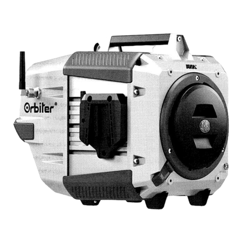
ARRI Orbiter User manual

ARRI

ARRI Orbiter User manual

ARRI L Series User manual

ARRI

ARRI L Series User manual

ARRI M Series User manual

ARRI

ARRI M Series User manual

ARRI L1.0009652 User manual

ARRI

ARRI L1.0009652 User manual

ARRI ARRISUN 12 Plus User manual

ARRI

ARRI ARRISUN 12 Plus User manual

ARRI ARRIMAX 18/12 User manual

ARRI

ARRI ARRIMAX 18/12 User manual

ARRI Studio Cool 4 User manual

ARRI

ARRI Studio Cool 4 User manual

ARRI L10-C User manual

ARRI

ARRI L10-C User manual

ARRI ARRI D 5 User manual

ARRI

ARRI ARRI D 5 User manual

ARRI EB MAX 2,5/4 User manual

ARRI

ARRI EB MAX 2,5/4 User manual

ARRI COMPACT 6000 Plus Manual

ARRI

ARRI COMPACT 6000 Plus Manual

ARRI CLAYPAKY TAMBORA LINEAR 60 User manual

ARRI

ARRI CLAYPAKY TAMBORA LINEAR 60 User manual

ARRI M18 User manual

ARRI

ARRI M18 User manual

ARRI ARRI D 5 User manual

ARRI

ARRI ARRI D 5 User manual

ARRI EB 400/575 D User manual

ARRI

ARRI EB 400/575 D User manual

ARRI Case for Orbiter User manual

ARRI

ARRI Case for Orbiter User manual

ARRI L0.0003381 User manual

ARRI

ARRI L0.0003381 User manual

ARRI ARRILITE 750 Plus User manual

ARRI

ARRI ARRILITE 750 Plus User manual

ARRI M Series User manual

ARRI

ARRI M Series User manual

ARRI SkyPanel User manual

ARRI

ARRI SkyPanel User manual

ARRI DAYLIGHT 18/12 PLUS User manual

ARRI

ARRI DAYLIGHT 18/12 PLUS User manual

Popular Lighting Equipment manuals by other brands

NORTHCLIFFE HELM S LED Installation instruction

NORTHCLIFFE

NORTHCLIFFE HELM S LED Installation instruction

Lightolier MBS2GPW154 Specification sheet

Lightolier

Lightolier MBS2GPW154 Specification sheet

ML Accessories MLRCTM2 Installation & maintenance manual

ML Accessories

ML Accessories MLRCTM2 Installation & maintenance manual

Microlights Eddi quick guide

Microlights

Microlights Eddi quick guide

Vision & Control A-DIF-120x180-G525-SL Instructions for use

Vision & Control

Vision & Control A-DIF-120x180-G525-SL Instructions for use

RAB HAZL34-40 instructions

RAB

RAB HAZL34-40 instructions

RAB Lighting ND4R installation instructions

RAB Lighting

RAB Lighting ND4R installation instructions

ensto Monix Slim Installation and operating instructions

ensto

ensto Monix Slim Installation and operating instructions

TRQ EYE-3W quick start guide

TRQ

TRQ EYE-3W quick start guide

Sycamore SY9016 installation instructions

Sycamore

Sycamore SY9016 installation instructions

Philips eW Reach Powercore installation instructions

Philips

Philips eW Reach Powercore installation instructions

LIVARNO LDS 3 A1 operating manual

LIVARNO

LIVARNO LDS 3 A1 operating manual

Larson Electronics GAU-EMG-2X5W-LED-WP instruction manual

Larson Electronics

Larson Electronics GAU-EMG-2X5W-LED-WP instruction manual

Osram KREIOS PAR manual

Osram

Osram KREIOS PAR manual

ABB Stanilite Quickfit Standard installation manual

ABB

ABB Stanilite Quickfit Standard installation manual

GE Tetra PowerMAX GEPM71-W1 installation guide

GE

GE Tetra PowerMAX GEPM71-W1 installation guide

ML Accessories TRIBCCW Installation & maintenance manual

ML Accessories

ML Accessories TRIBCCW Installation & maintenance manual

iSolution Lighting Equipment user guide

iSolution

iSolution Lighting Equipment user guide

manuals.online logo
manuals.online logoBrands
  • About & Mission
  • Contact us
  • Privacy Policy
  • Terms and Conditions

Copyright 2025 Manuals.Online. All Rights Reserved.