intensity setting is retained in memory until
readjusted/changed. When the dental
motor/handpiece is activated, either manually
or via the foot switch, the handpiece light will
automatically turn on at the previously used
intensity level (fiber optic light switch must be
‘On’) . When the dental motor/handpiece is
turned off, the handpiece light will stay on for
thirteen seconds before timing out.
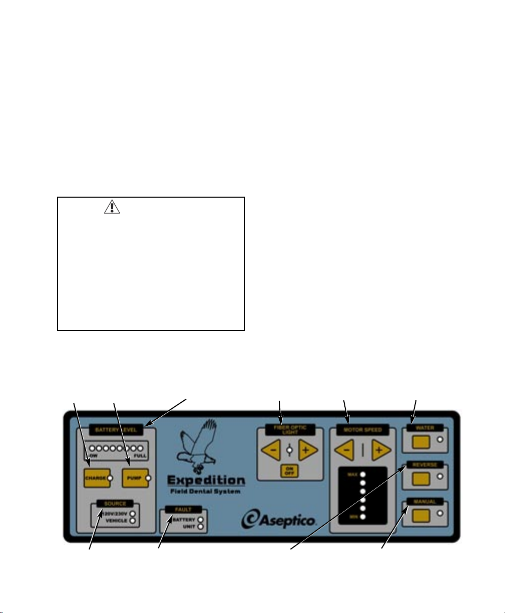
5. Manual – Manually activates the dental
motor, bypassing the need to use the foot
switch. When the LED is lit, the motor is
activated. When the LED is off, motor can be
activated via the foot switch.
6. Reverse – Selects clockwise or counter-
clockwise rotation of the motor handpiece bur.
When the LED light is on, the direction of the
bur is counterclockwise. When the LED is off,
the bur is turning clockwise.
7. Water – Controls the delivery of water to the
handpieces. When LED is lit, water is
delivered to the handpiece when the motor is
activated.
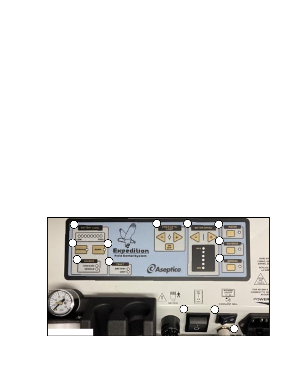
8. Source – Indicates power source. If 120V or
230V is powering the system, the LED will
light up. If vehicle 12V/24V is powering the
system, the vehicle LED will light up. If only
battery pack power is applied to the unit,
neither light will be on.
9. Charge – Allows the system to charge the
battery pack from a 120V/230V AC source or
vehicle battery when the LED is on. A drained
battery pack takes less than 4 hours to fully
charge. The unit is designed to charge the
battery pack while operating off 120V/230V
AC power or vehicle 12V/24V power. NOTE:
Charging via solar panel (included) takes
between 13-16 hours. Solar panel may be
used during operation. Charge button does
not need to be on to charge from solar panel.
10. Pump – When LED is on, power is applied to
the pump to allow for air and water pressure.
When LED is off, power is disengaged from
the pump to allow for water bottle removal
without shutting power off to the chassis or
battery charger.
11. Battery Level – Indicates level of charge for
the battery pack that is connected to the
chassis.
12. Fault – Battery light indicates problem with
connected battery pack. Unit light indicates
problem with the system. (Refer to
Troubleshooting Section)
13. Coolant Adj. – Controls the amount of water
flow to the handpiece - turn counterclockwise
to increase flow.
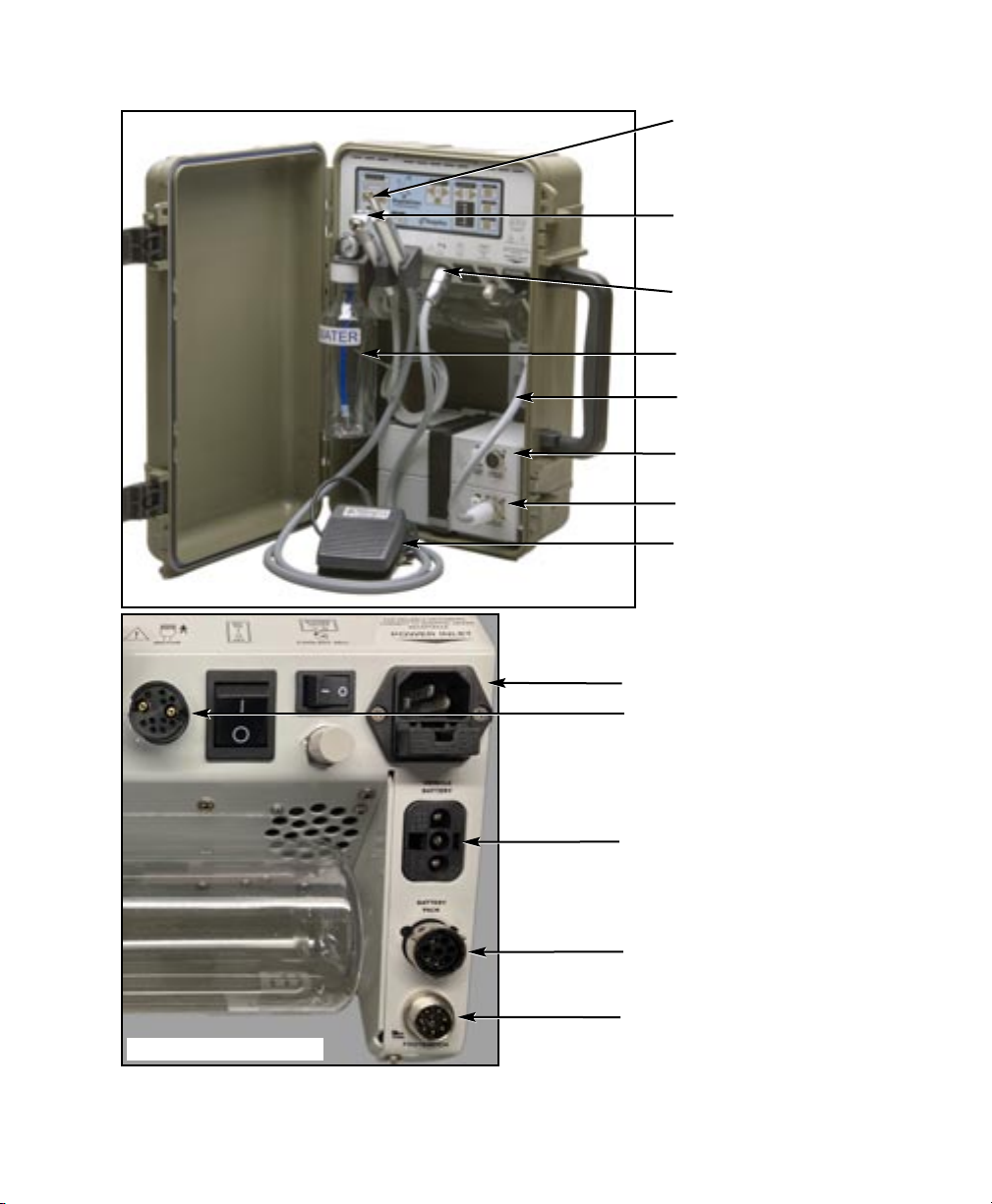
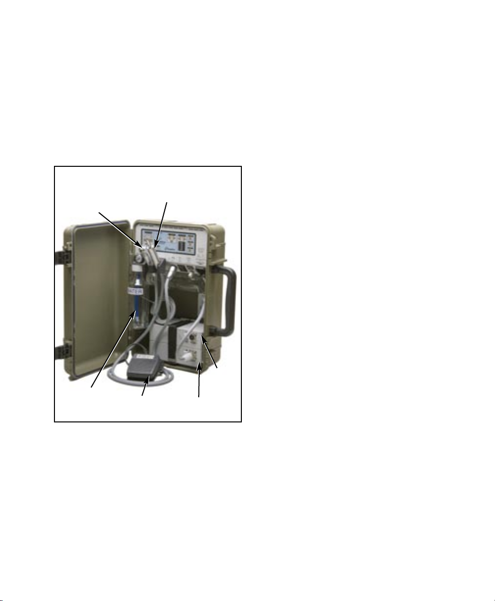
14. Foot Switch – The foot switch (see Fig. 6)
provides on/off operation of the dental motor
and water coolant (when water LED is on) to
the handpiece .
15. Three-way Air/Water Syringe (Fig. 6) -
Pressing the left button dispenses water.
Pressing the right button dispenses air.
Pressing both buttons simultaneously
dispenses an air/water mist.
16. Water Supply Bottle (Fig. 6) - The AEU-
14CF Expedition incorporates a self-
contained pressurized water system. This
consists of a 16 ounce clear bottle dispensing
water through the 3-way Air/Water Syringe
and Handpiece Coolant. The Water Supply
Bottle attaches to the threaded reservoir
connector, located below the pressure gauge.
To refill the Water Supply Bottle:
1. Disengage pump.
2. Unscrew bottle.
3. Fill with water.
4. Screw bottle onto reservoir connector.
5. Re-engage pump
6.