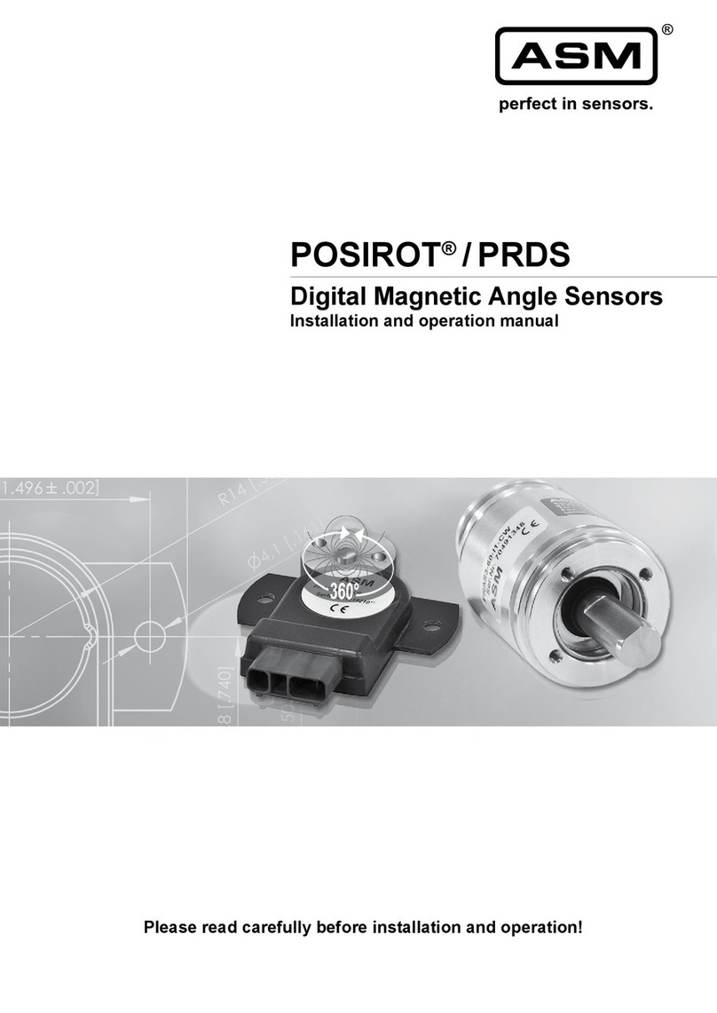
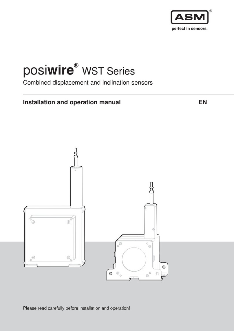
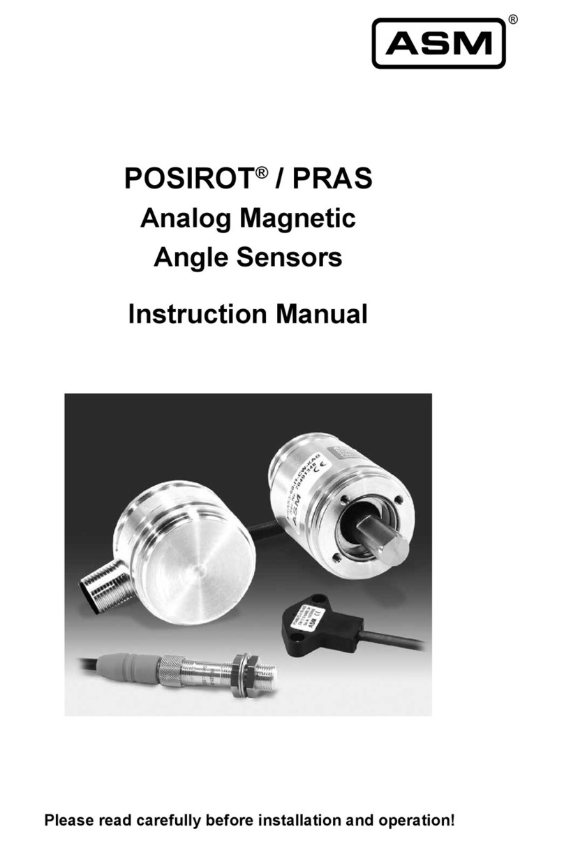
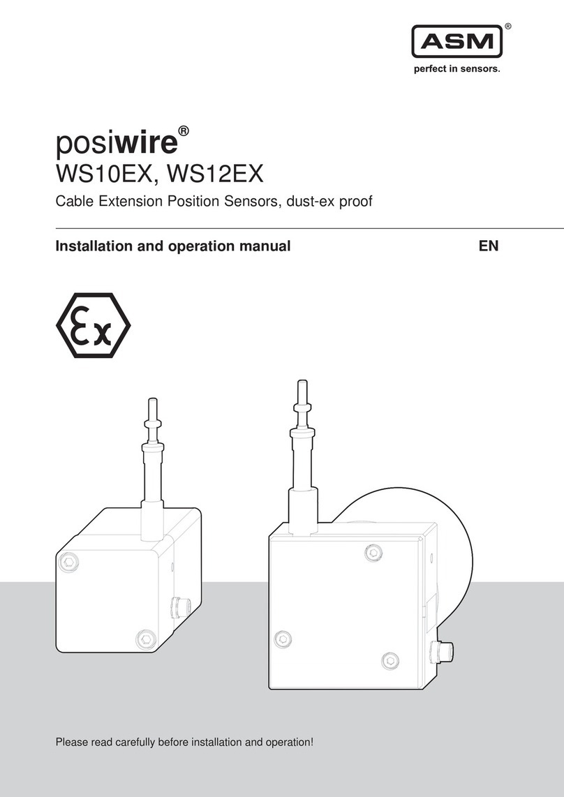
ASM posirot PRAS2EX User manual

Installation and operation manual EN
Please read carefully before installation and operation!
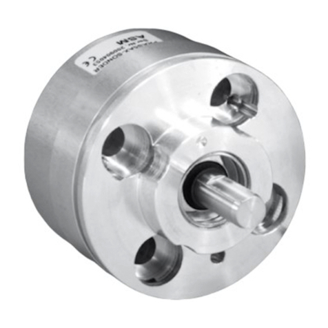
posirot®
PRAS2EX, PRAS3EX, PRAS5EX
Magnetic angle sensors, dust-ex proof

© ASM Automation Sensorik Messtechnik GmbH, 2019
All rights reserved.
Am Bleichbach 18 - 24
85452 Moosinning
Germany

posirot®
Magnetic angle sensors, dust-ex proof
Version 4.2.0
www.asm-sensor.com
3
1Safety instructions ........................................................................................................4
1.1 Signal words and symbols .............................................................................................................4
1.2 General safety instructions.............................................................................................................4
1.3 Dust-ex proof marking....................................................................................................................5
1.4 Intended use...................................................................................................................................6
2Transport and storage...................................................................................................7
3Installation and initial operation...................................................................................7
3.1 Mechanical installation...................................................................................................................7
3.2 Electrical installation.......................................................................................................................9
3.3 Operating temperature.................................................................................................................12
3.4 Characteristics for magnetic angle sensors.................................................................................13
4Maintenance and disposal..........................................................................................18
4.1 Maintenance and service .............................................................................................................18
4.2 Deinstallation (dust-ex proof standard-compliant) .......................................................................18
4.3 Disposal........................................................................................................................................18
5Output specification....................................................................................................19
6EU Declaration of Conformity.....................................................................................21

posirot®
Magnetic angle sensors, dust-ex proof
4
Version 4.2.0
www.asm-sensor.com
Pos: 6/ Bedienungsanleit ungen/Module Universal/Ü berschriften/Sicher heitshinweise UE @ 6\mod _1507630884828_78. docx @ 48429 @ 1@ 1
1 Safety instructions
Pos: 7/ Sicherheitshi nweise/Signalwört eru nd Symbole UE @ 1\m od_140014046 7807_78.docx @ 9166 @ 2 @1
1.1 Signal words and symbols
Pos: 8/ Sicherheitshin weise/Signalwörter @ 1\mod_1 400240492762_7 8.docx@ 9 385 @ @ 1
WARNING, Risk of Injury:
Indicates a potentially hazardous situation, which, if not avoided, can result in serious
injury or property damage.
WARNING, Risk of Personal Injury or Death:
Indicates a situation that can result in serious personal injury or death if not properly
avoided.
WARNING, Risk of Personal Injury or Death:
Indicates a situation that can result in moderate personal injury or death if not properly
avoided.
WARNING, Risk of Personal Injury:
Indicates a situation that can result in minor personal injury if not properly avoided.
WARNING, Risk of Property Damage:
Indicates a situation that can result in minor to major property damage if not properly
avoided.
Product liability
•Disregarding the following instructions may result in malfunction, damage to property and personal injury
and releases the manufacturer from product liability.
Safety regulations
•National safety regulations must be observed!
Pos: 9/ Sicherheitshin weise/Sicherheitshin weise_EX @ 8\mod_1566891 609782_78.docx @ 67520 @ 2 @ 1
1.2 General safety instructions
Danger of explosion! Danger of injury to persons or damage to the property
•Mounting or servicing of the sensor only by qualified personnel who must have
knowledge about the type of ex-protection, regulation and ordinance of operating
equipment in ex-proof areas.
Explosion risk due to use in non-conforming environment
•The sensor must only be used in the specified environment.
•Special notes concerning the electrical installation of dust-ex proof sensors must be
observed.
Pos: 10 /Sicherheitshinweis e/Sicherheitshinw eise_PRAS_PRDS @ 8\ mod_1557821952 218_78.docx @ 63749 @ @ 1
Danger of injury to the operator or damage to the property
•Connection to power supply must be performed in accordance with safety instructions
for electrical facilities and performed only by qualified personnel.
•Any alteration, reconstruction or extension of the sensor is not allowed!
•The sensor must be operated only within values specified in the datasheet.
•The danger of personal injury and danger of property damage due to a malfunction of
the sensor in machines or systems must be excluded by additional safety measures.

posirot®
Magnetic angle sensors, dust-ex proof
Version 4.2.0
www.asm-sensor.com
5
•In safety-relevant applications, additional facilities must be provided for maintaining
safety and preventing damage.
•Check whether the protection class of the sensor is suitable for the application.
Pos: 11 /Bedienungs anleitungen/Posirot /EX/Kennzeich nungd er PRAS-EX-Sensor en@ 7\m od_1522761936717_ 78.docx @ 55005 @ 2 @ 1
1.3 Dust-ex proof marking
The Dust-ex proof marking according to the guideline 2014/34/EU is lasered on the sensor housing.
These are:
PRAS2EX, PRAS5EX-K:
II 3D
Ex tc IIIC T80°C Dc X
PRAS3EX, PRAS5EX-V:
II 3D
Ex tc IIIC T80°C Dc X
max. 1000rpm
This means:
II
=
Equipment-group II: Equipment not intended for use in underground parts of mines, as
well as their overground plants, which are endangered by firedamp or/and combustible
dusts
3
=
Equipment category 3: Normal level of safety –application in dust explosion hazardous
areas. Equipment in this category is intended for use in areas in which explosive
atmospheres –in the case of this sensor caused by dispersed dust –are unlikely to
occur, or, if they do occur, are likely to do so only infrequently and for a short period
only. Equipment in this category ensures the requisite level of protection during normal
operation.
D
=
Air/dust mixture
EX
=
This symbol indicates that the electrical equipment complies with one or more types of
protection
Tc
=
Ignition protection class: protection by enclosure IP65
IIIC
=
Group for conductive dust
T80°C
=
Maximum surface temperature of the angle sensor
Dc
=
Equipment Protection Level (EPL): EPL „Dc“ complies with the categorie 3D
X
=
Resists an impact with reduced impact energy of 4J, without X the sensor resists an
impact of 7J impact energy
max.
1000rpm
=
Max. revolutions of 1000 1/min resp. max. 1000rpm are admissible. A higher number of
revolutions can cause the surface temperature to exceed 80°C.
Pos: 12 /######## ### Seitenumbruch #### ############## ############# #### @ 0\mod_13 53584168894_0.d ocx @ 336 @ @ 1

posirot®
Magnetic angle sensors, dust-ex proof
6
Version 4.2.0
www.asm-sensor.com
Pos: 13 /Sicherheits hinweise/Bestimmu ngsgemäße Verwen dung/Bestimmungsg emäße Verwen dungU E @ 1\mod_1 400142179648_ 78.docx @ 9192 @ 2 @ 1
1.4 Intended use
Pos: 14 /Bedienungs anleitungen/Posirot /EX/Bestimmung sgemäße Verwend ung PRAS_EX @ 5\ mod_14993298 18175_78.docx @ 443 05@ @ 1
The angle sensor is intended for angle position measurement via rotation of the position magnet or rotation
of the shaft. For determining measuring range, environmental compatibility and connection data of the
sensor, please note the data sheet. Use the sensor as intended by operating within its specified technical
data and ambient conditions. The environmental conditions are specified in the dust-ex proof category of the
sensor.
The installation and operating instructions supplied with the unit must be observed and all maintenance and
service work must be carried out. The data sheet of the respective sensor is part of this instruction manual. If
not yet available, it may be requested by stating the respective model number.
The sensor must not be used in applications with an explosive gas atmosphere or higher explosive dust
atmosphere that requires a higher rated device.
Do not use the sensor in the following environmental conditions:
•abrasive dust e.g. dust including metal or metaloxid, stone dust, glass dust, ceramic dust
•corrosive and aggressive media e.g. atmospheres containing chloride.
Pos: 15 /######## ### Seitenumbruch #### ############## ############# #### @ 0\mod_13 53584168894_0.d ocx @ 336 @ @ 1

posirot®
Magnetic angle sensors, dust-ex proof
Version 4.2.0
www.asm-sensor.com
7
Pos: 16 /Bedienungs anleitungen/Mo duleU niversal/Transp ort und Lagerung EX @ 7\ mod_1522329367 168_78.doc x@ 5499 3 @ 1 @ 1
2 Transport and storage
Loss of explosion protection in case of shipment damages
•Damaged sensors may no longer meet the specified EX rating and must not be
mounted and operated in explosion-risk areas.
Observe storage and transport temperatures according to the operating temperature (see data sheet)
Max. rel. humidity 60%, condensation must be excluded
The device must be secured against slipping and tipping during transport.
Shipment damage
Check sensor immediately for shipment damage. In case of any damage or equipment not operating
appropriately, please contact your supplier.
Shipment content
•Sensor
•Installation and operation manual
Pos: 17 /Bedienungs anleitungen/Mo duleU niversal/Überschrift en/Montage, In betriebnahme UE @ 4\ mod_149147469 4256_78.doc x@ 38 324 @ 1 @1
3 Installation and initial operation
Pos: 18 /Bedienungs anleitungen/Posirot /EX/Allgemeine Mo ntagehinweise_ PRAS_EX @ 5\mo d_149933278194 4_78.docx @ 44328 @ 2 @ 1
3.1 Mechanical installation
Danger of explosion due to the overheating of the sensor
•Avoid dust deposits.
•Do not exceed the maximum number of revolutions of 1000 1/min (1000 RPM).
Danger of explosion due to the static charge of the sensor
•Do not mount the sensor in the dust particle stream.
Danger of explosion due to the spark flashover in case of insufficient
equipotential bonding
•Use electrically conductive shafts/torque arms.
•Sensor housing and sensor shaft must be connected to the same equalization
system.
Fixing of the sensor
•Secure mounting screws against loosening, use thread locker if necessary.
•Mount sensor with corrosion-resistant screws.
•Mount sensor on a flat metallic surface.
•Provide protection devices to avoid damage or blocking of sensor and magnet by foreign objects falling
into the working area.
Mechanical information for PRAS2EX and PRAS5EX-K
•Contact between sensor and magnet is not allowed.

posirot®
Magnetic angle sensors, dust-ex proof
8
Version 4.2.0
www.asm-sensor.com
Mechanical information for PRAS3EX and PRAS5EX-V
•The max. number of revolutions is 1000 1/min (1000 RPM)
•Ensure the sensor is mounted and aligned correctly.
•Use shaft couplings resp. torque arms (e.g. flexible ones) to avoid misalignment errors.
Torque of the fixing screws
Mounting method
Torque [Nm]
M2,5 screws for mounting brackets (PRAS2, PRAS3)
0.8
M3 screws for mounting flange (PRAS3)
1.2
M8 screws (PRAS5)
<20
Pos: 19 /Bedienungsanl eitungen/Posirot/EX/M ontage_Anordnung_ PRAS_EX @ 5\mod_14 99332275976_78.d ocx @ 44322@ @ 1
Placement and alignment of the position magnet
When mounting the position magnets, consider that a large air gap, lack of parallelism and lateral
misalignment to the sensor can cause measuring errors. Also, external magnetic fields and magnetized
materials nearby can affect the measuring result.
Pos: 20 /Bedienungsanl eitungen/Posirot/EX/ Seitenversatz_Tabelle _PRAS_EX @ 5\mod_1 499333757012_7 8.docx@ 4 4336 @ @ 1
Measuring error by misalignment of the position magnet
Air gap (a)
Parallelism (b)
Axial misalignment (c)
Sensor
Position
magnet
Air gap
[mm]
Paral-
lelism
[°]
Error by axial misalignment [°]
0.2
mm
0.5
mm
1 mm
2 mm
3 mm
4 mm
PRAS2EX
PRMAG2-VA
0 ... 5
5
0.1
0.3
0.8
1.8
6.5
-
PRMAG2Z-VA
0 ... 9
5
0.1
0.2
0.6
1.5
4.5
8.5
PRMAG5Z-VA
0 ... 8
5
0.1
0.2
0.6
1.5
4.5
8.5
PRAS5EX
PRMAG2-VA
0 ... 4.5
5
0.1
0.3
0.8
1.8
6.5
-
PRMAG2Z-VA
0 ... 5.5
5
0.1
0.2
0.6
1.5
4.5
8.5
PRMAG5Z-VA
0 ... 7.5
5
0.1
0.2
0.6
1.5
4.5
8.5
Pos: 21 /######## ### Seitenumbruch # ############## ############## ###### @ 0\mod_13 53584168894_0.d ocx @ 336 @ @ 1

posirot®
Magnetic angle sensors, dust-ex proof
Version 4.2.0
www.asm-sensor.com
9
Pos: 22 /Bedienungsanl eitungen/Posirot/EX/ Elektr. Anschluss_PRAS_E X@ 5\ mod_14993342 38776_78.docx @ 44342 @ 2 @ 1
3.2 Electrical installation
Explosion risk!
•Mounting / removal of the sensor under non-explosible conditions only.
Damage or destruction of the sensor due to excessive operating voltage or
mounting error
•The applied operating voltage must not exceed the value specified in the data
sheet.
•Operate the sensor only within the limits specified in the data sheet.
•Connection to the power supply only by qualified personnel and in accordance with
the applicable safety regulations for electrical equipment.
•Do not connect or disconnect the sensor under tension!
Corrosion in the sensor due to moisture penetration
•Use the sensor only according to protection class.
•Avoid crossing the dew point.
•Cable outputs must be installed in such a way that no moisture can get into the
cable.
•The protection class of sensors with connector output is valid only if the electrical
plug is connected!
Damage of the sensor cable due to mechanical stress
•Use only M12 sockets approved in compliance with ATEX which allow
deinstallation only with tools, eg. EVC 04A or EVC 05A of ifm/Essen.
•Do not twist the M12 connector insert.
•It is important that the knurled nut on the connector is tightened to the correct
torque, according to the manufacturer’s instruction. Use a torque wrench, if
needed.
•Cable must be properly secured and protected against damage.
•Cable must be protected from UV-radiation!
•Installation according to DIN EN 60079-14.
•Do not strain the connection cable.
•A separate strain relief is recommended.
Connector Pin assignment
According to the definitions of the output types contained in the appendix. Observe different color code for
pre-assembled accessory cables. See catalog information for accessories.
Connect the cable screen - if present - to the local potential equalizer.
Follow the signal wiring table!
Supply voltage
See specification in the data sheet of the sensor. The maximum operating voltage must not be exceeded.
Pos: 23 /######## ### Seitenumbruch #### ########### ############## ###### @ 0\mod_13 53584168894_0.d ocx @ 336 @ @ 1
posirot®
Magnetic angle sensors, dust-ex proof
10
Version 4.2.0
www.asm-sensor.com
Pos: 24 /Bedienungs anleitungen/Posirot /EX/Potentialausg leich_PRAS_EX @5 \mod_149933 5533446_78.doc x@ 4 4360 @ @ 1
Potential equalization
The local potential equalization has to be realized with a wire cross section of 4 mm² minimum.
PRAS2EX
PRAS3EX
PRAS5EX-K
PRAS5EX-V
Pos: 25 /######## ### Seitenumbruch #### ############## ############# #### @ 0\mod_13 53584168894_0.d ocx @ 336 @ @ 1

posirot®
Magnetic angle sensors, dust-ex proof
Version 4.2.0
www.asm-sensor.com
11
Pos: 26 /Bedienungs anleitungen/Mo duleU niversal/Montage S ensorkabel @ 6\ mod_15196512352 86_78.docx @ 52835 @ @ 1
Installation of the sensor supply cable
incorrect
correct
Admissible bending radius of the
cable must be observed:
R ~ 5 x D
R ~ 10 x D (underwater cable)
Length compensation for the
cable must be observed
A separate cord grip for cable
strain relief is recommended
Observe cable routing in case of
splashing water, water
condensation and humidity
Pos: 27 /######## ### Seitenumbruch #### ############## ############# #### @ 0\mod_13 53584168894_0.d ocx @ 336 @ @ 1

posirot®
Magnetic angle sensors, dust-ex proof
12
Version 4.2.0
www.asm-sensor.com
Pos: 28 /Bedienungsanl eitungen/Posirot/PR_E X_EMV @ 7\mod_1521 461903570_78.docx @ 5413 8@ @ 1
Electromagnetic Compatibility (EMC)
Electromagnetic compatibility of posirot®dust-ex proof magnetic angle sensors is influenced by the sensor
wiring.
Pos: 29 /Bedienungs anleitungen/Posirot /EX/Arbeitstemper atur_Übersicht _PRAS_EX @ 7\m od_15359683070 46_78.docx @ 58505 @ 2 @ 1
3.3 Operating temperature
posirot® PRAS2EX
-20 … +40°C
posirot® PRAS3EX
-20 … +40°C
posirot® PRAS5EX
-20 … +40°C
Pos: 30 /######## ### Seitenumbruch #### ############## ############# #### @ 0\mod_13 53584168894_0.d ocx @ 336 @ @ 1
Possible malfunction of the sensor when used in systems with highly
interference-prone components such as frequency inverters
Recommended wiring:
•Use single shielded sensor cable with twisted pair conductors for power supply
and signal output.
•Connect the cable shield to ground on one side of the control cabinet. Connect
the shield connection over a large area using cable clamps before or at the cable
entry into the control cabinet. When preassembled cables are delivered, the
screen is not connected to the housing on the sensor side.
•Do not install sensor cables close to power conductors such as motor or
contactor control cables (use separate cable ducts for signal and power cables).
•Install the cables in metal cable ducts which are connected to the same earth
bonding as the dust-ex proof sensors.

posirot®
Magnetic angle sensors, dust-ex proof
Version 4.2.0
www.asm-sensor.com
13
Pos: 31 /Bedienungsanl eitungen/Posirot/PRAS /Kennlinien_Refere nzpos.@ 2 \mod_144283 4669819_78.doc x@ 20118 @ 2 @ 1
3.4 Characteristics for magnetic angle sensors
For ease of mounting there are reference markings at housing, position magnet and near the shaft. If both
markings match output will be on the 50% of full scale.
Output signal
(CW increasing*)
Output signal
(CCW increasing*)
Example angular range 90°
Example angular range 360°
A –Marking
B –Measurement range [°]

posirot®
Magnetic angle sensors, dust-ex proof
14
Version 4.2.0
www.asm-sensor.com
*: Rotation direction of the sensor axis / of the position magnet with a view to the sensor
Pos: 32 /Bedienungs anleitungen/Posirot /PRAS/Werteberei ch EX @ 7\mod_1 523351566517_7 8.docx @ 55045 @ @ 1
Output
Value range
50% value of output signal
U2
0.5 ... 10 V
5.25 V
U6
0.5 ... 4.5 V
2.5 V
I1
4 ... 20 mA
12 mA
Pos: 33 /######## ### Seitenumbruch #### ############## ############# #### @ 0\mod_13 53584168894_0.d ocx @ 336 @ @ 1
posirot®
Magnetic angle sensors, dust-ex proof
Version 4.2.0
www.asm-sensor.com
15
Pos: 34 /Bedienungs anleitungen/Posirot /EX/Referenzpositi on_EX/Refpos _PRAS2_EX_M 12ax_rad @ 5\mod_ 1499337731501_7 8.docx @ 44376 @ @ 1
Reference position PRAS2EX
Connector M12 axial
Connector M12 radial
A –Marking
Magnets:
PRMAG2-VA
PRMAG2Z-VA
PRMAG5Z VA
A –Marking
Magnets:
PRMAG2-VA
PRMAG2Z-VA
PRMAG5Z VA
Pos: 35 /######## ### Seitenumbruch #### ############## ############# #### @ 0\mod_13 53584168894_0.d ocx @ 336 @ @ 1
posirot®
Magnetic angle sensors, dust-ex proof
16
Version 4.2.0
www.asm-sensor.com
Pos: 36 /Bedienungsanl eitungen/Posirot/EX/R eferenzposition_EX /Refpos_PRAS3_E X_M12_ax_rad_voll welle @ 5\mod_14993 39150955_78.doc x@ 44396 @ @ 1
Reference position PRAS3EX, solid shaft
Connector M12 axial
Connector M12 radial
A –Marking
B –Marking (back side)
Pos: 37 /Bedienungs anleitungen/Posirot /EX/Referenzpositi on_EX/Refpos _PRAS3_EX_M 12_ax_rad_hohl welle @ 5\mod_149 9413423263_78.d ocx @ 44485 @ @ 1
Reference position PRAS3EX with hollow shaft
Connector M12 axial
Connector M12 radial
A –Marking
B –Marking (back side)
Pos: 38 /######## ### Seitenumbruch #### ############## ############# #### @ 0\mod_13 53584168894_0.d ocx @ 336 @ @ 1

posirot®
Magnetic angle sensors, dust-ex proof
Version 4.2.0
www.asm-sensor.com
17
Pos: 39 /Bedienungsanl eitungen/Posirot/EX/R eferenzposition_EX /Refpos_PRAS5_E X_V_M12_ax_rad @ 5\ mod_1499417120215 _78.docx @ 44515 @ @ 1
Reference position PRAS5EX-V
Connector M12 axial
Connector M12 radial
A –Marking
B –Flat area
Pos: 40 /Bedienungs anleitungen/Posirot /EX/Referenzpositi on_EX/Refpos _PRAS5_EX_K _M12_ax_rad @ 5\ mod_14994174 45244_78.docx @ 445 30@ @ 1
Reference position PRAS5EX-K
Connector M12 axial
Connector M12 radial
A –Marking
B –Marking (front side)
Pos: 41 /######## ### Seitenumbruch # ############## ############## ###### @ 0\mod_13 53584168894_0.d ocx @ 336 @ @ 1
posirot®
Magnetic angle sensors, dust-ex proof
18
Version 4.2.0
www.asm-sensor.com
Pos: 42 /Bedienungs anleitungen/Mo duleU niversal/Überschrift en/Instandh altung und Entsorgung U E@ 6 \mod_150763 0731526_78.docx @ 4 8417 @ 1 @ 1
4 Maintenance and disposal
Pos: 43 /Bedienungsanl eitungen/Posirot/EX/Inst andhaltung_Wart ung_PRAS-EX @ 5\mod_ 1500370631881_78. docx @ 45141 @ 2@ 1
4.1 Maintenance and service
Explosion risk!
•Maintenance may only be performed when no explosive atmospheric conditions are
present.
Maintenance interval
•Within maintenance activities, especially those parts of the sensor which are associated with the risk of
ignition must be checked (e.g. the integrity of connectors, cables, seals etc.). Maintenance intervals are
application specific and must be determined by the customer depending on the operating conditions.
•Dust concentrations between sensor and magnet are not allowed –remove any dust deposit –
appropriate maintenance intervals must be scheduled.
The following maintenance steps are recommended:
Check for dust
deposit
Integrity of
housing, cables
connectors
Mounting
elements
Visual check of
shaft sealing
PRAS2EX
x
x
x
PRAS3EX
x
x
x
x
PRAS5EX-K
x
x
x
PRAS5EX-V
x
x
x
x
Actions
Dust deposit:
Remove dust
Damaged parts:
remove sensor
from service and
send it to ASM for
repair
Loose mounting
parts: Screw tight
mounting parts
with recommended
torque, if
applicable use bolt
adhesive
Damaged shaft
sealing:
remove sensor
from service and
send it to ASM for
repair
Pos: 44 /Bedienungsanl eitungen/Posiwire/W S_EX_Demontage @ 6\m od_1519816144724 _78.docx @ 52912 @ 2 @ 1
4.2 Deinstallation (dust-ex proof standard-compliant)
Danger of explosion due to incorrect deinstallation
•Remove sensor only in de-energized condition.
•Removal of the sensor must only be undertaken in non-explosive conditions.
Pos: 45 /Bedienungsanl eitungen/Posiwire/W S_Kalibrierung @ 4\mod _1491566471251_78. docx@ 3 8399 @ @ 1
Calibration
The recommended calibration interval is 1 year.
Test protocol and traceable calibration certificate (ISO9001 / ISO10012) is available on request.
Pos: 46 /Bedienungsanl eitungen/Posiwire/W S_Entsorgung @ 6\mod_15 07649730932_78. docx @ 48485 @ 2@ 1
4.3 Disposal
Disposal according to applicable government regulations.
Pos: 47 /######## ### Seitenumbruch #### ############## ############# #### @ 0\mod_13 53584168894_0 .docx @ 336 @ @ 1

posirot®
Magnetic angle sensors, dust-ex proof
Version 4.2.0
www.asm-sensor.com
19
Pos: 48 /Ausgangs arten/Spezifikatio nAusga ngU E @ 1\mod _1397662705340_7 8.docx @ 8534 @ 1 @ 1
5 Output specification
Pos: 49 /Ausgangs arten/Posirot/Analog -Ausgänge/An alog-Ausgänge UE @ 1\ mod_1396873901 708_78.docx @ 795 8 @ @ 1
Analog output
Pos: 50 /Ausgangsarten/Po sirot/Analog-Ausg änge/U2-EX @ 3\mod_146 1230645939_78. docx@ 24 084 @ @ 1
U2
Voltage output
0.5 ... 10 V
Excitation voltage
24 V DC (18 … 36 V DC)
Excitation current
typical 10 mA
max. 15 mA
Output voltage
0.5 ... 10 V DC
Output current
2 mA max.
Measuring rate
1 kHz standard
Stability (temperature)
±50 x 10-6 / °C f.s. (typical for 90° … 360°)
±100 x 10-6 / °C f.s. (typical for <90°)
Protection
Reverse polarity, short circuit
Operating temperature
-40 … +85 °C
EMC
DIN EN 61326-1:2013
Pos: 51 /Ausgangs arten/Posirot/Analog -Ausgänge/U 6 @1\ mod_139687473 3793_78.doc x@ 80 06@ @ 1
U6
Voltage output
10 … 90 % ratiometric
Excitation voltage
5 V DC ±10 %
Excitation current
typical 8 mA
max. 12 mA
Output voltage
10 … 90 % of the excitation voltage
Output current
2 mA max.
Measuring rate
1 kHz standard
Stability (temperature)
±50 x 10-6 / °C f.s. (typical for 90° … 360°)
±100 x 10-6 / °C f.s. (typical for <90°)
Protection
Reverse polarity, short circuit
Operating temperature
-40 … +85 °C
EMC
DIN EN 61326-1:2013
Pos: 52 /######## ### Seitenumbruch #### ############## ############# #### @ 0\mod_13 53584168894_0.d ocx @ 336 @ @ 1
posirot®
Magnetic angle sensors, dust-ex proof
20
Version 4.2.0
www.asm-sensor.com
Pos: 53 /Ausgangsarten/Po sirot/Analog-Ausg änge/I1-EX @ 3\mod_14 61230894120_78.d ocx@ 240 90@ @ 1
I1
Current output
4 … 20 mA, 3 wires
Excitation voltage
24 V DC (18 … 36 V DC)
Excitation current
typical 30 mA
max. 35 mA
Load RL
500 max.
Output current
4 … 20 mA
Measuring rate
1 kHz standard
Stability (temperature)
±50 x 10-6 / °C f.s. (typical for 90° … 360°)
±100 x 10-6 / °C f.s. (typical for <90°)
Protection
Reverse polarity, short circuit
Operating temperature
-40 … +85 °C
EMC
DIN EN 61326-1:2013
Pos: 54 /Ausgangsarten/Po sirot/Analog-Ausg änge/Anschluss belegung-EX @ 3\mod_146 1741312907_78.doc x@ 2412 4@ @ 1
1 channel M12, 5 pin (connector output)
Signal wiring
Connector M12, 5 pin
View to the sensor
connector
Output signals
Connector pin no.
Excitation +
1
Signal
2
GND
3
Do not connect!
4
Do not connect!
5
3-wire current 4...20 mA interface: GND has to be connected!
Pos: 55 /######## ### Seitenumbruch #### ############## ############# #### @ 0\mod_13 53584168894_0.d ocx @ 336 @ @ 1
This manual suits for next models
2
Table of contents
Other ASM Accessories manuals

ASM
ASM POSIROT PRAS User manual

ASM
ASM Posirot PRAS2 User manual

ASM
ASM POSIROT Series User manual

ASM
ASM posirot PRAS Series User manual

ASM
ASM posiwire User manual

ASM
ASM posirot PRAS Series User manual

ASM
ASM Posihall PH36 Owner's manual

ASM
ASM POSITAPE WB Series User manual

ASM
ASM posirot PRAS Series User manual

ASM
ASM PRDS-CANOPR User manual
Popular Accessories manuals by other brands

rollease acmeda
rollease acmeda AUTOMATE manual

SCENTED INTERIORS BY DESIGN
SCENTED INTERIORS BY DESIGN DELUXE user guide

izzy
izzy SLEEPY IZ-9008 instruction manual

Dynamax
Dynamax SapIP-IRT instruction manual

Desoutter
Desoutter CVI3 Vision user manual

Cornelius
Cornelius Universal 750 Pre-Mix installation instructions