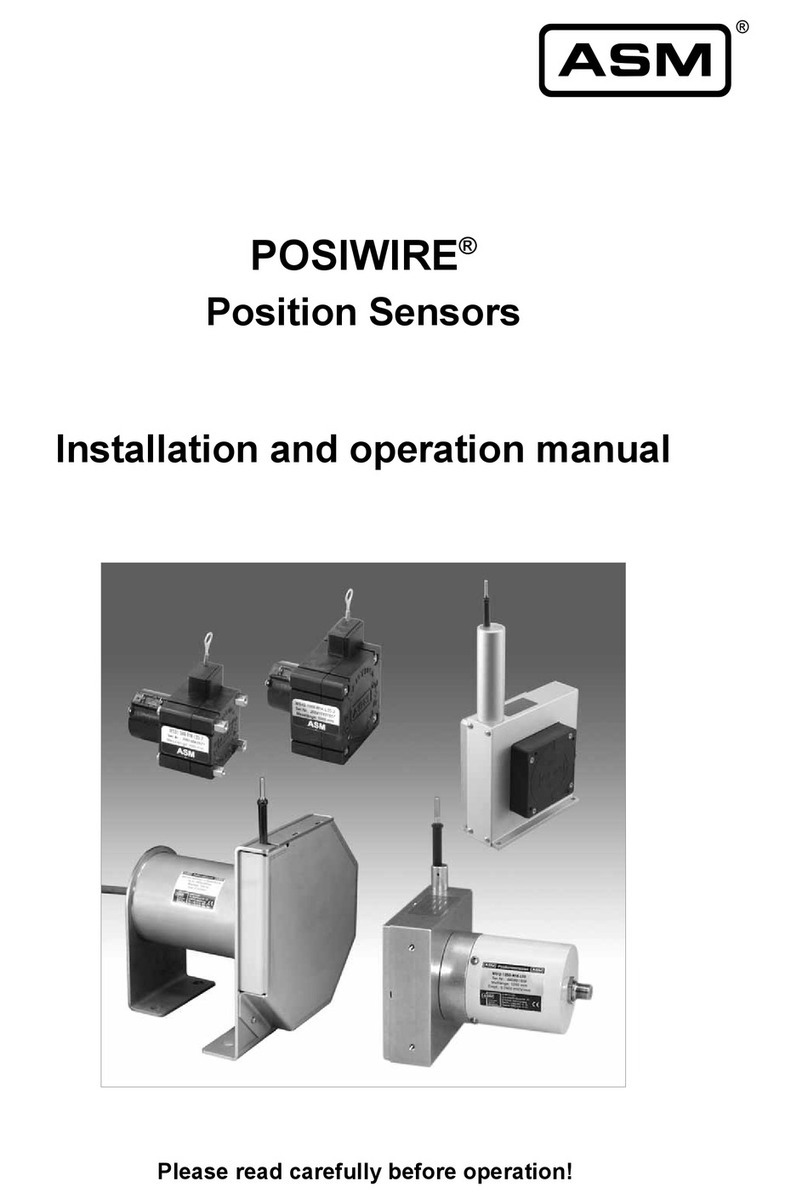
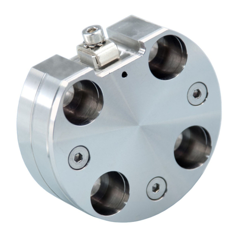
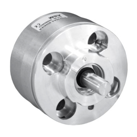
ASM positilt PTM Series User manual

Installation and operation manual EN
Please read carefully before installation and operation!
positilt® PTM Series
Inclination Sensors
positilt® PTK Series
Gyro-compensated Inclination Sensors

© ASM Automation Sensorik Messtechnik GmbH, 2020
All rights reserved.
Am Bleichbach 18 - 24
85452 Moosinning
Germany

positilt®
Inclination Sensors PTM series
Gyro-compensated Inclination Sensors PTK series
Version 1.0.0
www.asm-sensor.com 3
1Safety instructions ........................................................................................................4
1.1 Signal words and symbols .............................................................................................................4
1.2 General safety instructions.............................................................................................................4
1.3 Intended use...................................................................................................................................5
2Transport and storage...................................................................................................5
3Installation and initial operation...................................................................................5
3.1 Mechanical installation ...................................................................................................................5
3.2 Electrical connection ......................................................................................................................6
3.3 Operating temperature ...................................................................................................................7
3.4 Position of the inclination axis and output characteristics...............................................................8
4Maintenance and disposal ..........................................................................................13
4.1 Maintenance and disposal ...........................................................................................................13
4.2 Disposal........................................................................................................................................13
5Output specification....................................................................................................14
5.1 Analog output (only PTM sensors)...............................................................................................14
5.2 Digital output ................................................................................................................................17

positilt®
Inclination Sensors PTM series
Gyro-compensated Inclination Sensors PTK series
4
Version 1.0.0
www.asm-sensor.com
Pos: 6/Be di en ungs a nlei tung en /Mo d ule U ni ver sal /Ü ber schr if te n/Si ch er heits hi nw eis e U E @ 6\mod_1507630884828_78.docx@ 48429@ 1 @ 1
1 Safety instructions
Pos: 7 / Si ch er hei ts hi nwei s e/ Si g nal wör t er und Sym b ol e UE @1\m od_1400140467807_78.docx@ 9166 @ 2 @ 1
1.1 Signal words and symbols
Pos: 8 / Si ch er hei ts hi nwei s e/ Si g nal wör t er @1 \mod_1400240492762_78.docx@ 9385 @ @1
WARNING, Risk of Injury:
Indicates a potentially hazardous situation, which, if not avoided, can result in serious
injury or property damage.
WARNING, Risk of Personal Injury or Death:
Indicates a situation that can result in serious personal injury or death if not properly
avoided.
WARNING, Risk of Personal Injury or Death:
Indicates a situation that can result in moderate personal injury or death if not properly
avoided.
WARNING, Risk of Personal Injury:
Indicates a situation that can result in minor personal injury if not properly avoided.
WARNING, Risk of Property Damage:
Indicates a situation that can result in minor to major property damage if not properly
avoided.
Product liability
•Disregarding the following instructions may result in malfunction, damage to property and personal injury
and releases the manufacturer from product liability.
Safety regulations
•National safety regulations must be observed!
Pos: 9/Si ch er hei ts hi nwei s e/ All g_Si c h erh eits hi nw ei se U E @ 0\mod_1385398033298_78.docx @ 2610@ 2 @ 1
1.2 General safety instructions
Pos: 10 /Sich erh eit s hinw ei s e/Sic h er hei ts hinw ei s e_ PT @8\mod_1557828733936_78.docx@63907 @ @1
Danger of injury to the operator or damage to the property
•Connection to power supply must be performed in accordance with safety
instructions for electrical facilities and performed only by qualified personnel.
•Any alteration, reconstruction or extension of the sensor is not allowed!
•The sensor must be operated only within values specified in the datasheet.
•The danger of personal injury and danger of property damage due to a
malfunction of the sensor in machines or systems must be excluded by
additional safety measures.
•In safety-relevant applications, additional facilities must be provided for
maintaining safety and preventing damage.
•Check whether the protection class of the sensor is suitable for the application.
Mechanical damage or destruction of the sensor
•Do not open the sensor.
•Avoid impact and shock to the sensor.
Pos: 11 / ##### ##### # Seite numbr uch ###################################@ 0\mod_1353584168894_0.docx@ 336 @ @1


positilt®
Inclination Sensors PTM series
Gyro-compensated Inclination Sensors PTK series
Version 1.0.0
www.asm-sensor.com 5
Pos: 12/Si c h erh eits hi nw ei s e/Bes t im mu ng sg emäß e Verwend ung / Bes tim mu ng sg em äße Verwe ndu ng UE @ 1\m od_1400142179648_78.d ocx @ 919 2 @ 2 @ 1
1.3 Intended use
Pos: 13 /Bedie nu ngs anl eit ungen/Positilt/Bestimmungsgemäße VerwendungPTM_PTK@ 9\mod_1600327869909_78.docx@ 73985@ @ 1
positilt®inclination sensors of PTM series measure inclination between ±15° and ±180° utilizing MEMS
technology.
positilt®inclination sensors of PTK series measure inclination between ±15° and ±180° utilizing gyro-
compensated MEMS technology.
For determining measuring range, environmental compatibility and connection data of the sensor, please
note the data sheet. Use the sensor as intended by operating within its specified technical data and ambient
conditions.
The installation and operating instructions supplied with the unit must be respected. All maintenance and
service work must be carried out. The data sheet of the respective sensor is part of this instruction manual. If
not yet available, it may be requested by stating the respective model number.
The sensor must not be improperly mounted, operated or serviced. In addition, operation of the sensor in
faulty condition is prohibited.
Pos: 14/B e die nu ngs anl eit ung e n/M o dul e U ni ver s al/T r ans p ort und Lag er u ng @ 3\mod_1485160671089_78.docx @ 33682@ 1@ 1
2 Transport and storage
Observe storage and transport temperatures according to the temperatures specified in the data sheet.
Max. rel. humidity 60%, dew condensation must be prevented at all times.
The device must be secured against slipping and tipping during transport.
Pos: 15/B e die nu ngs anl eit ung e n/M o dul e U ni ver s al/ Lief er umf ang @6 \mod_1512125907439_ 78.doc x @ 50022 @ @ 1
Shipment damage
Check sensor immediately for shipment damage. In case of any damage or equipment not operating
appropriately, please contact your supplier.
Shipment content
•Sensor
•Installation and operation manual
Pos: 16/B e die nung s anl eitu nge n/M o dul e U niv ers al/ Ü bersc hr ift e n/Mo ntag e , I nbe tr ieb nahm e U E @4\mod_1491474694256_78.docx @ 38324 @ 1 @ 1
3 Installation and initial operation
Pos: 17 /Bedie nu ngs anl eit ung e n/ Pos iti lt/M ec h. Anschl uss _PT K _PTM @ 6\mod_1512399865809_78.docx @ 50194@ 2 @ 1
3.1 Mechanical installation
Torque for fixing screws
The specified torques and mounting methods are general recommendations and can differ according to
application and operating conditions.
Mounting method Torque [Nm]
Screws M4 1
Pos: 18/########### Seitenumbruch###################################@ 0\mod_1353584168894_0.docx@ 336@ @ 1

positilt®
Inclination Sensors PTM series
Gyro-compensated Inclination Sensors PTK series
6
Version 1.0.0
www.asm-sensor.com
Pos: 19/B e die nu ngs anl eit ung e n/P os iti lt/ El ek tr. Anschl uss _PT K @ 9\mod_1587620105034_78.docx@ 71686@ 2 @ 1
3.2 Electrical connection
Damage or destruction of the sensor due to excessive operating voltage or
mounting error
•The applied operating voltage must not exceed the value specified in the data
sheet.
•Operate the sensor only within the limits specified in the data sheet.
•Connect to the power supply only by qualified personnel and in accordance with
the applicable safety regulations for electrical equipment.
•Do not connect or disconnect the sensor under voltage!
Corrosion in the sensor due to moisture penetration
•Use the sensor only according to protection class.
•The mating connector should have the same protection class as the sensor,
otherwise the lower protection class of the mating connector is valid.
•Avoid crossing the dew point.
•Cable outputs must be installed in such a way that no moisture can get into the
cable.
•The protection class of sensors with connector output is valid only if the electrical
plug is connected!
Damage of the sensor cable due to mechanical stress
•Do not twist the M12 connector inserts.
•It is important that the knurled nuts on the connectors are tightened to the correct
torque for each different size of the connector:
•M12-ASM connectors / couplings: 1.0 Nm
•connectors / couplings of other manufacturers: according to manufacturer
instruction.
•Use a torque wrench.
•Do not strain the connection cable.
•A separate cord grip is recommended.
Pos: 20 / ##### ##### # Seite numbr uch ###################################@ 0\mod_1353584168894_0.docx@ 336 @ @1

positilt®
Inclination Sensors PTM series
Gyro-compensated Inclination Sensors PTK series
Version 1.0.0
www.asm-sensor.com 7
Pos: 21/B e di e nu ng s anl ei tu ng e n/ P osi ti lt / PT_ EM V @ 7 \mod_1524743788399_78. docx @ 551 61 @ @ 1
Electromagnetic Compatibility (EMC)
Electromagnetic compatibility of positilt®inclination sensors is influenced by the sensor wiring.
Pos: 22/B e di enu ng s anl eitu ng e n/ P osi til t/ Ar b eits t em per at ur PT M _ PT K @ 8\mod_1549629637212_78.docx @ 61803@ 2 @ 1
3.3 Operating temperature
positilt® PTM27 -40 … +85°C
positilt® PTM29 -40 … +85°C
positilt® PTK29 -40 … +85°C
positilt® PTK6 -40 … +85°C
positilt® PTK7 -40 … +85°C
Pos: 23 / ##### ##### # Seite numbr uch ###################################@ 0\mod_1353584168894_0.docx@ 336 @ @1
Possible malfunction of the sensor when used in systems with highly
interference-prone components such as frequency inverters
Recommended wiring:
•Use single shielded sensor cable with twisted pair conductors for power supply
and signal output.
•Connect the cable shield to ground on one side of the control cabinet. Connect
the shield connection over a large area using cable clamps before or at the cable
entry into the control cabinet. When preassembled cables are delivered, the
screen is not connected to the housing on the sensor side.
•Do not install sensor cables close to power conductors such as motor or
contactor control cables (use separate cable ducts for signal and power cables).
•Install the cables in metal cable ducts which are connected to ground.

positilt®
Inclination Sensors PTM series
Gyro-compensated Inclination Sensors PTK series
8
Version 1.0.0
www.asm-sensor.com
Pos: 24 /Bedienungsanl eitungen/Positilt/Kennlinien ptm _ptk U E@ 9\m od_1602244032804_78.docx @ 74125 @2 @ 1
3.4 Position of the inclination axis and output characteristics
Pos: 25 /D atenblätter/Positilt/Zubehör/Kennli nie_PTM 27_Anal og_Achsausrichtung @ 9\m od_1594627964113_78.docx @73521@ @1
PTM27 - Output characteristic and axis orientation
Sensor position as shown equals 0°.
1 Measuring axis 2 Measuring axes
Axis orientation
1A
Axis orientation
2A
Axis orientation
1B
Axis orientation
2B
Axis orientation
1C
Axis orientation
2C
Output signal
Pos:26/###########Seitenumbruch################################### @ 0\mod_1353584168894_0.docx@ 336 @ @ 1

positilt®
Inclination Sensors PTM series
Gyro-compensated Inclination Sensors PTK series
Version 1.0.0
www.asm-sensor.com 9
Pos: 27 /D atenblätter/Positilt/Zubehör/Kennli nie_PTM 29_Anal og_Achsausrichtung @ 9\m od_1590480535509_78.docx @ 72355@ @1
PTM29 - Output characteristic and axis orientation
Sensor position as shown equals 0°.
1 Measuring axis 2 Measuring axes
Axis orientation
1A
Axis orientation
2A
Axis orientation
1B
Axis orientation
2B
Axis orientation
1C
Axis orientation
2C
Output signal
Pos:28/###########Seitenumbruch################################### @ 0\mod_1353584168894_0.docx@ 336@ @ 1

positilt®
Inclination Sensors PTM series
Gyro-compensated Inclination Sensors PTK series
10
Version 1.0.0
www.asm-sensor.com
Pos: 29 /D atenblätter/Positilt/Zubehör/Kennli nie_PT K29_Achsausrichtung_C AN @ 9\mod_1602149676018_78.docx@ 74055 @ @1
PTK29 - Output characteristic and axis orientation
For CAN output, the axis orientation can be set by the user via software.
Sensor position as shown equals 0°.
2 measuring axes
Axis orientation 2A
Axis orientation 2B
Axis orientation 2C
Output signal
Pos:30/###########Seitenumbruch################################### @ 0\mod_1353584168894_0.docx@ 336@ @ 1

positilt®
Inclination Sensors PTM series
Gyro-compensated Inclination Sensors PTK series
Version 1.0.0
www.asm-sensor.com 11
Pos: 31 /D atenblätter/Positilt/Zubehör/Kennli nie_PT K6_Achsausrichtung_C AN @ 9\m od_1602151112692_78.docx @ 74067 @@1
PTK6 - Output characteristic and axis orientation
For CAN output, the axis orientation can be set by the user via software.
Sensor position as shown equals 0°.
2 measuring axes
Axis orientation 2A
Axis orientation 2B
Axis orientation 2C
A = Marking
Output signal
Pos:32/###########Seitenumbruch################################### @ 0\mod_1353584168894_0.docx@ 336@ @ 1

positilt®
Inclination Sensors PTM series
Gyro-compensated Inclination Sensors PTK series
12
Version 1.0.0
www.asm-sensor.com
Pos: 33 /D atenblätter/Positilt/Zubehör/Kennli nie_PT K7_Achsausrichtung_C AN @ 9\m od_1602151674341_78.docx @ 74072 @@1
PTK7 - Output characteristic and axis orientation
For CAN output, the axis orientation can be set by the user via software.
Sensor position as shown equals 0°.
2 measuring axes
Axis orientation 2A
Axis orientation 2B
Axis orientation 2C
A = Marking
Output signal

positilt®
Inclination Sensors PTM series
Gyro-compensated Inclination Sensors PTK series
Version 1.0.0
www.asm-sensor.com 13
Pos: 34/B e die nung s anl eitu nge n/M o dul e U niv ers al/ Ü bersc hr ift e n/Ins ta nd hal tung und E nts org ung UE @ 6 \mod_1507630731526_78.docx@ 48417 @ 1@ 1
4 Maintenance and disposal
Pos: 35 /Bedie nu ng s anl ei tu ng e n/ Pos it il t/ Ins ta n dh alt ung _B ef est ig u ng sel em e nt e PT M _PT K @ 6 \mod_1512398065430_78.docx@50156 @ 2@ 1
4.1 Maintenance and disposal
Opening all the positilt® PTM and PTK sensors will cause damage and void the
warranty
•Do not open the sensor.
•Due to possible risk of injury by improper handling, we strongly advise against
repair attempts.
Maintenance interval
Proper maintenance comprises the visual examination of parts (e.g. integrity of housing, connectors and
cables). Maintenance intervals depend on the specific application and should be defined by the user in
dependence of operating conditions. Damaged sensors must be shut down immediately and sent to the
factory for repair.
Check sensor regularly for possible damage. The following maintenance steps are recommended:
Integrity of housing,
connector, cable
Mounting elements
PTM27 X X
PTM29 X X
PTK29 X X
PTK6 X X
PTK7 X X
Maßnahmen Damaged parts: Put sensor out of
service and replace damaged
parts resp. send sensor to ASM
for repair
Loose mounting parts: Screw
tight mounting parts with
recommended torque, if
applicable use bolt adhesive
Pos: 36/B e die nu ngs anl eit ung e n/P os iwi re/ W S_ Ent s org ung @ 6\mod_1507649730932_78.docx @ 48 485 @ 2 @ 1
4.2 Disposal
Disposal according to applicable government regulations.
Pos:37/###########Seitenumbruch################################### @ 0\mod_1353584168894_0.docx@ 336@ @ 1

positilt®
Inclination Sensors PTM series
Gyro-compensated Inclination Sensors PTK series
14
Version 1.0.0
www.asm-sensor.com
Pos: 38/A us g ang s ar te n/ Po si til t/D ig i tal a us gä ng e/ Sp ez . d er Ausgang s ar t en U E @ 6\mod_1512462073567_78.docx@ 50215@ 1 @ 1
5 Output specification
Pos: 39 /Ausg ang s ar te n/ Po sit il t/ An alog -Ausgänge/Analog-Ausgänge_ptmUE @ 9\mod_1602148451830_78.docx @ 74049@ 2@ 1
5.1 Analog output (only PTM sensors)
Pos: 40 /Ausg ang s ar te n/ Po si til t/ An alog -Ausgänge/U2_ptm@ 9\mod_1589960751206_78.docx@ 72295@ @ 1
U2
Voltage output
0.5 ... 10 V
Excitation voltage 8 … 36 V DC
Excitation current typical 12 mA
max. 16 mA
Output voltage 0.5 ... 10 V DC
Output current 2 mA max.
Measuring rate 1 kHz standard
Stability (temperature) ±50 x 10-6 / °C f.s. (typical)
Protection Reverse polarity, short circuit
Operating temperature -40 … +85 °C
EMC DIN EN 61326-1:2013
Pos: 41/A us g ang s ar te n/ Po si til t/ An al og-A usgänge/U8_ptm @ 9\mod_1589960876865_78.docx @ 72300@ @1
U8
Voltage output
0.5 … 4,5 V
Excitation voltage 8 … 36 V DC
Excitation current typical 12 mA
max. 16 mA
Output voltage 0.5 … 4,5 V DC
Output current 2 mA max.
Measuring rate 1 kHz standard
Stability (temperature) ±50 x 10-6 / °C f.s. (typical)
Protection Reverse polarity, short circuit
Operating temperature -40 … +85 °C
EMC DIN EN 61326-1:2013
Pos: 42/A us g ang s ar te n/ Po si til t/ An al og-A usgänge/U6_ptm @ 9\mod_1595398200175_78.docx @ 73565@ @1
U6
Voltage output
0.5 … 4.5 V
Excitation voltage 5 V DC ±10 %
Excitation current typical 13 mA
max. 16 mA
Output voltage 10 … 90 % of the excitation voltage
Output current 2 mA max.
Measuring rate 1 kHz standard
Stability (temperature) ±50 x 10-6 / °C f.s. (typical)
Protection Reverse polarity, short circuit
Operating temperature -40 … +85 °C
EMC DIN EN 61326-1:2013
Pos:43/###########Seitenumbruch################################### @ 0\mod_1353584168894_0.docx@ 336@ @ 1

positilt®
Inclination Sensors PTM series
Gyro-compensated Inclination Sensors PTK series
Version 1.0.0
www.asm-sensor.com 15
Pos: 44/A us g ang s ar te n/ Po si til t/ An al og-A usgänge/I1_ptm@ 9\mod_1595398338751_78.docx@ 73570@ @ 1
I1
Current output
4 … 20 mA, 3 wires
Excitation voltage 8 … 36 VDC
Excitation current typical 32 mA
max. 36 mA
Load RL500 Ωmax.
Output current 4 … 20 mA
Measuring rate 1 kHz standard
Stability (temperature) ±50 x 10-6 / °C f.s. (typical)
Protection Reverse polarity, short circuit
Operating temperature -40 … +85 °C
EMC DIN EN 61326-1:2013
Pos: 45/A us g ang s ar te n/ Po si til t/ An al og-A us g ä ng e/ A nsc hl u ss b eleg ung _K abel _PT M 29 @9\m od_1594202133686_78.docx@ 73505@ @1
Signal wiring
1 axis
Output signals Cable color
+UB(excitation voltage)brown
Output X white
GND blue
Do not connect! grey
Signal wiring
2 axes
Output signals Cable color
+UB(excitation voltage)brown
Output X white
GND blue
OUTPUT Y black
Do not connect! grey
Pos: 46 / ##### ##### # Seite numbr uch ###################################@ 0\mod_1353584168894_0.docx@ 336 @ @1

positilt®
Inclination Sensors PTM series
Gyro-compensated Inclination Sensors PTK series
16
Version 1.0.0
www.asm-sensor.com
Pos: 47/A us g ang s ar te n/ Po si til t/ An al og-A us g ä ng e/ A nsc hl u ss b eleg ung _St eck er _K ab el @ 3\mod_145829577713 0_78. docx @ 2353 0 @ @ 1
Analog output (connector and cable output, only PTM sensors)
Signal wiring 1 axis
Connector M12, 5 pin
View to the sensor
connector
Output signals Connector pin no. Cable color
+UB(excitation voltage) 1 brown
Analog output X axis 2 white
GND 3 blue
Do not connect! 4 black
Do not connect! 5 grey
Signal wiring 2 axes
Connector M12, 5 pin
View to the sensor
connector
Output signals Connector pin no. Cable color
+UB(excitation voltage) 1 brown
Analog output X axis 2 white
GND 3 blue
Analog output Y axis 4 black
Do not connect! 5 grey
Pos: 48/ ###########Seitenumbruch###################################@ 0\mod_1353584168894_0.docx@ 336@ @ 1

positilt®
Inclination Sensors PTM series
Gyro-compensated Inclination Sensors PTK series
Version 1.0.0
www.asm-sensor.com 17
Pos: 49/A usg ang s art en/ PR M Encoder/ MC ANO P/ Di gi t al -AusgängeUE@ 6\mod_1519810710463_78.docx@ 52900 @ 2@ 1
5.2 Digital output
Pos: 50 /Ausg ang s arte n/ Po sitilt/Digitalausgänge/CANOP/CANopen_PTK@ 5\mod_1499765399505_78.docx@ 44640@ @1
CANOP
CANopen
Communication profile CANopen CiA 301, Slave
Encoder profile CiA 410, Profile „Inclinometer“
Configuration services LSS, CiA Draft Standard 305
(Transmission rate, node ID)
Error Control Node guarding, Heartbeat, Emergency
message
Node ID Adjustable via LSS or SDO, default: 127
PDO 1 TxPDO, 0 RxPDO, no linking, static
mapping
PDO Modes Event-/Time triggered, Remote-request, Sync
cyclic/acyclic
SDO 1 Server, 0 Client
Certified yes
Transmission rate 125 kBit … 1 Mbit, adjustable via LSS or
SDO, default: 125 kBit
Bus connection M12 conncector, 5 pin
Bus, galvanic isolated no
Error Control Baudrate 50 kBit/s … 1 MBit/s configurable
Transceiver 24V-compliant, not isolated
Internal termination resistor 120 Ohm configurable
Specifications
Excitation voltage 8 ... 36 V DC
Excitation current 15 mA typical at 24 V DC
30 mA typical at 12 V DC
100 mA max.
Measuring rate 0.5 kHz standard
Stability (temperature) ± 0,2° (-20 … +40 °C)
± 0,4° (-40 … +85 °C)
Repeatability 1 LSB
Operating temperature -40 … +85 °C
Protection Reverse polarity, short circuit
EMC DIN EN 61326-1:2013

positilt®
Inclination Sensors PTM series
Gyro-compensated Inclination Sensors PTK series
18
Version 1.0.0
www.asm-sensor.com
Signal wiring
Connector M12, 5 pin
View to the sensor
connector
Output signals Connector pin no.
Shield 1
Excitation + 2
GND 3
CAN-H 4
CAN-L 5
Pos: 51/B e die nu ngs anl eit ung e n/P os ita p e/C ANo p en_s pec _W S_W B/C AN o p_s etu p @7\mod_1527003732700_78.docx@56023 @ @1
CANopen – Set up (MCANOP)
Download
•A detailed specification of this interface can be downloaded from the ASM website:
www.asm-sensor.com/en/downloads.html > Configuration files
Risk of injury by unexpected machine movement
•Change parameters only when machine is in a safe condition!
•Changing parameters may cause unexpected machine movement.
•Changing parameters may influence dependent parameters e.g. changing the
resolution may have influence on position of CAM switches.
•Precautions have to be taken to avoid damage to human and machine parts!
Pos:52/###########Seitenumbruch################################### @ 0\mod_1353584168894_0.docx@ 336@ @ 1

positilt®
Inclination Sensors PTM series
Gyro-compensated Inclination Sensors PTK series
Version 1.0.0
www.asm-sensor.com 19
Pos: 53/A us g angsarten/Positilt/Digitalausgänge/CANSAEJ 1939/SAEJ1939_PTK@ 5\mod_1499765399958_78.docx@ 44645 @ @1
CANJ1939
SAE J1939
CAN Specification ISO 11898, Basic and Full CAN 2.0 B
extended message format with 29-bit
identifier
Transceiver 24V-compliant, not isolated
Communication profile SAE J1939, 29-bit identifier
Transmission rate 250 kBit/s
Internal termination resistor 120 Ω
Address Default 247d, configurable
NAME - Unique
device identifier
Name Fields Remark Field
value
Size
[Bit]
Byte
order
Byte
value
Arbitrary Address
Capable
No 0 1 Byte 8
(MSB)
00h
Industry Group Global 0 3
Vehicle System
instance
0 4
Vehicle System Non specific 7Fh 7 Byte 7 FEh
Reserved 0 1
Function Non specific FFh 8 Byte 6 FFh
Function Instance 0 5 Byte 5 00
ECU Instance 0 3
Manufacturer Manufacturer Code 145h 11 Byte 4 28h
Byte 3 A0h+n
n
Identity Number n..nh 21
Byte 2 nnh
Byte 1 nnh
Proprietary PGN -
Manufacturer
specific Parameter
Group Numbers
Configuration data PGN EFddh Proprietary-A
(PDU1 peer-to-peer)
Process data PGN FFnnh Proprietary-B
(PDU2 broadcast);
nn Group Extension (PS)
configurable

positilt®
Inclination Sensors PTM series
Gyro-compensated Inclination Sensors PTK series
20
Version 1.0.0
www.asm-sensor.com
Specifications
Excitation voltage 8 ... 36 V DC
Excitation current 15 mA typical at 24 V DC
30 mA typical at 12 V DC, 100 mA max.
Measuring rate 0.5 kHz (asynchronous)
Stability (temperature) ± 0,2° (-20 … +40 °C)
± 0,4° (-40 … +85 °C)
Repeatability 1 LSB
Operating temperature -40 … +85 °C
Protection Reverse polarity, short circuit
EMV DIN EN 61326-1:2013
Signal wiring
Connector M12, 5 pin
View to the sensor
connector
Output signals Connector pin no.
Shield 1
Excitation + 2
GND 3
CAN-H 4
CAN-L 5
Pos: 54/B e di e nu ng s anl ei tu ng e n/ P osi ta p e/ SA E J 1 93 9/ SA E J 1 93 9_ se t up @ 7\mod_1527060993387_78.docx @ 56033@ @ 1
SAE J1939 – Set up (MCANJ1939)
Download
•A detailed specification of this interface can be downloaded from the ASM website:
www.asm-sensor.com/en/downloads.html > Configuration files
Risk of injury due to unexpected machine movement
•Change parameters only when machine is in a safe condition!
•Changing parameters may cause unexpected machine movement.
•Changing parameters may influence dependent parameters e.g. changing the
resolution may have influence on position of CAM switches.
•Precautions have to be taken to avoid damage to human and machine parts!
Pos: 55 / ##### ##### # Seitenumbruch################################### @ 0\mod_1353584168894_0.docx@ 336@ @ 1
This manual suits for next models
15
Table of contents
Other ASM Accessories manuals

ASM
ASM posirot PRAS Series User manual

ASM
ASM Posirot PRAS2 User manual

ASM
ASM POSITAPE WB Series User manual

ASM
ASM posirot PRAS2EX User manual

ASM
ASM posiwire WS10EX User manual

ASM
ASM positape WBT Series User manual

ASM
ASM posiwire User manual

ASM
ASM PRDS-CANOPR User manual

ASM
ASM posirot PRAS Series User manual

ASM
ASM POSIROT PRAS User manual