© by ASM GmbH MAN-WS-E-15 9
www.asm-sensor.com
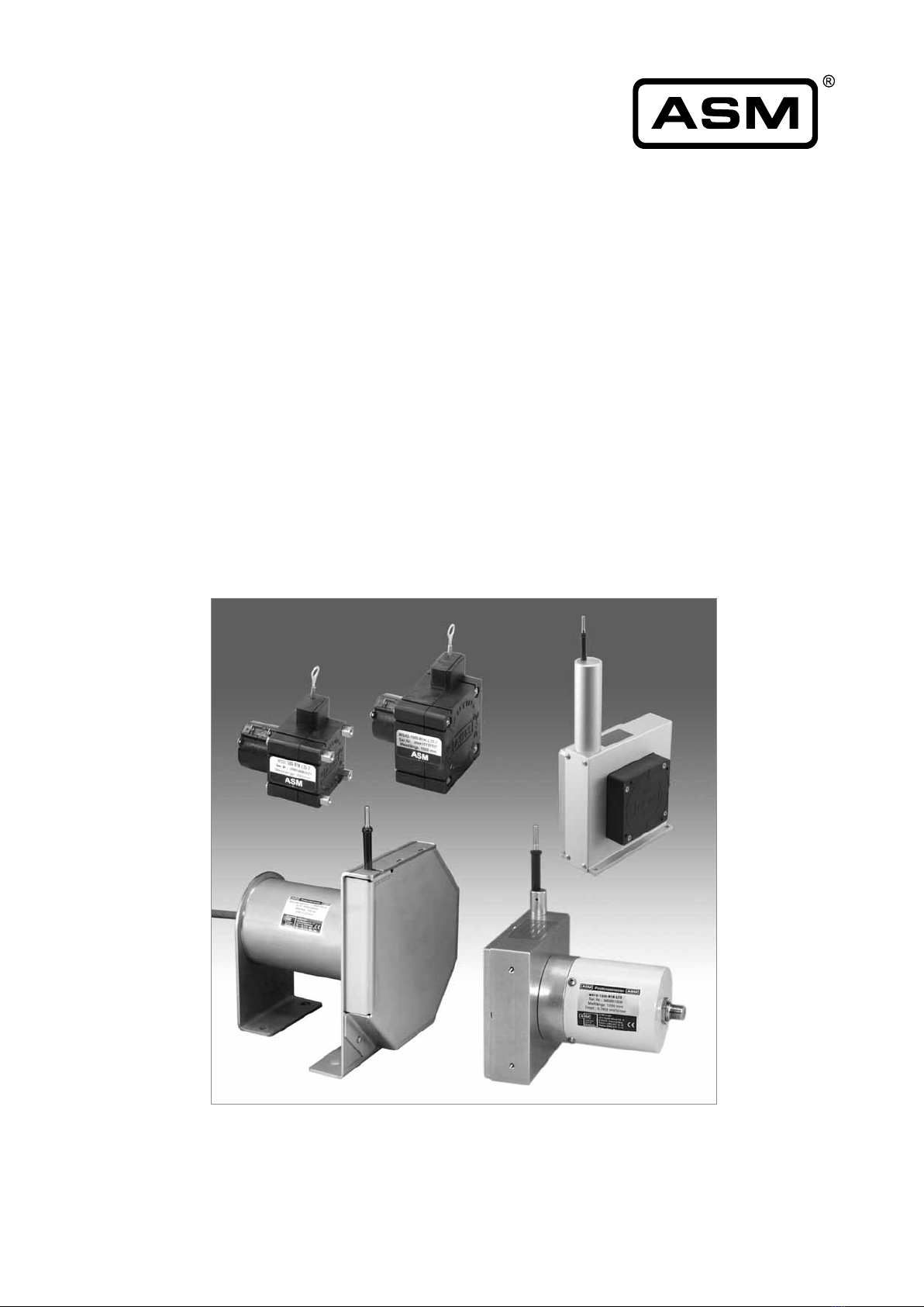
POSIWIRE®
Instruction Manual
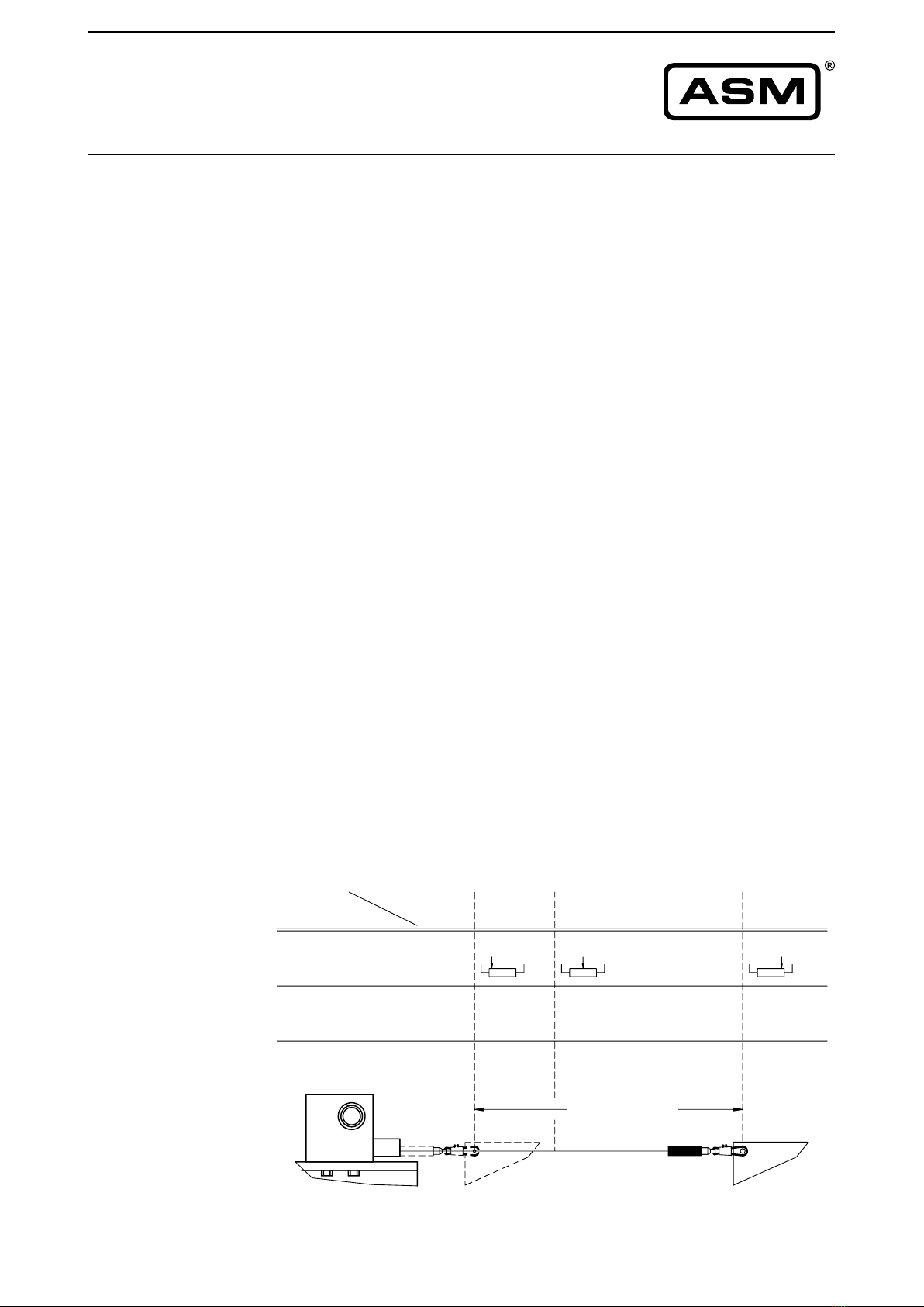
Installation Installation position
Cable travel should only be axial to the cable outlet
- no misalignment is allowed.
Cable misalignment shortens service life of sensor and causes error
in measurement. Warranty will not be granted for damage caused by
misalignment.
Ifcabletravelaxialtothecableoutletisnotpossible,thecableguidewheel
SR2(accessories)mustbeusedinordertoturnthecable.
For special applications extension cables with clips on both ends are
available.
Fitting the sensor
Depending upon the sensor model, holes in the base plate, threads or T-
slots in the sensor housing enable attachment of the sensor. Dimensions
required are listed in the catalog.
Cable attachment device
For fastening the cable clip the following solutions are available. For
example:
a)SetscrewM5: Standardxing.
(Allenscrew)
b)AttachmentheadGK1/GK2: Fastcableattachment,easyto
(accessory) remove.
c) Magnetic clamp MAG1: An easy way to fasten the cable to
(accessory) ferromagneticmaterials.
The mounting of the M4 connection is made with a through hole and a M4
nut. Note: Do not screw the M4 connection itself into a stationary object,
otherwise the measuring cable will be twisted!
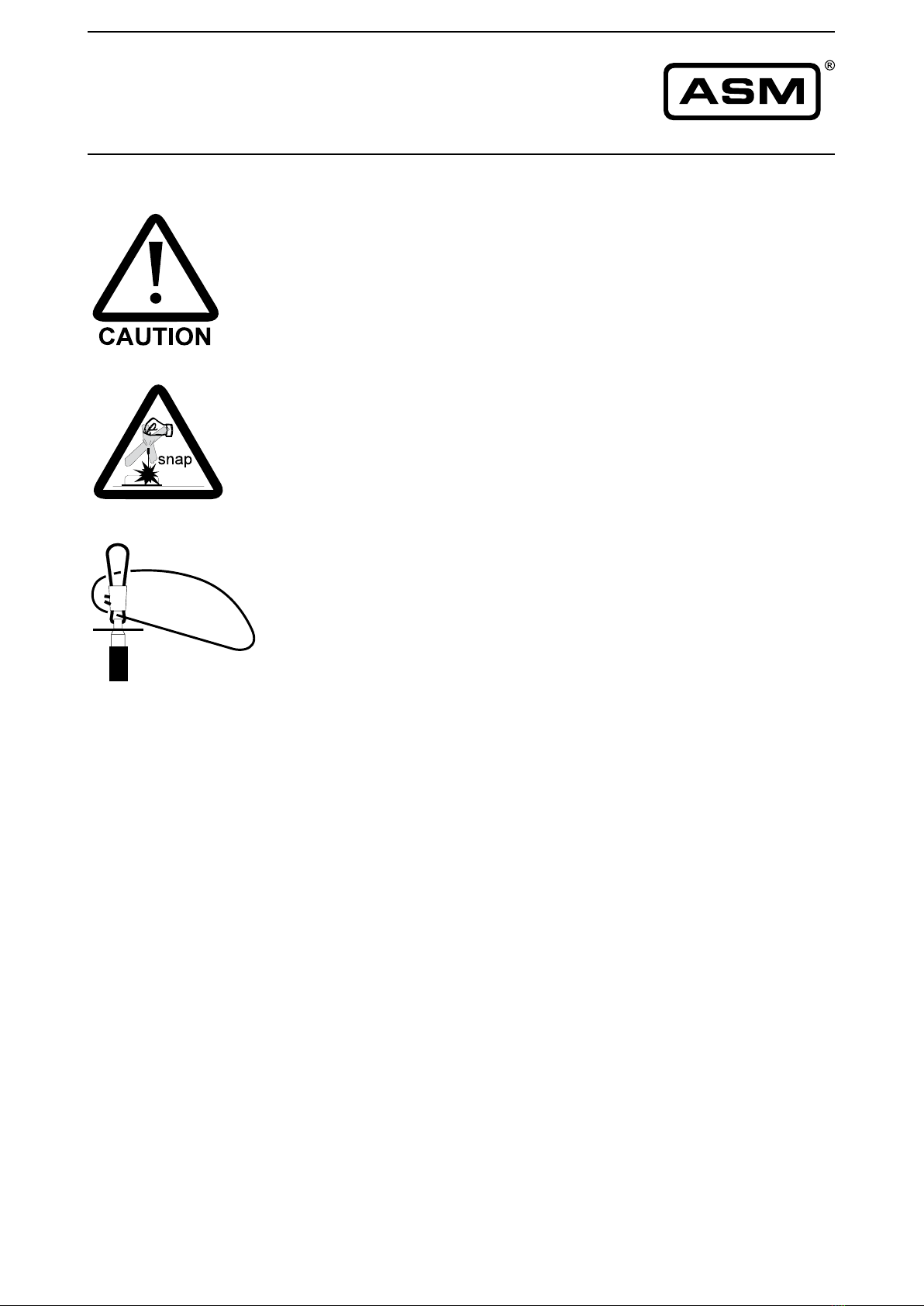
Cable clip attachment
When fastening the cable clip take notice of the chapter Installation / Pre-
cautions(page8).
This prevents cable from damage,
soiling and manipulation.
Soaking of liquids into the cable out-
let is impossible, concentration of
condensing water will be avoided.
This prevents sensor from bending
and damage.
Covered or shielded travel of cable
is preferred.
Cable outlet is preferred pointing
downwards.
Fit sensor on plain base or use three-
point mounting on uneven surfaces.