ASM PRDS-CANOPR User manual

Installation and operation manual EN
Please read carefully before installation and operation!
posirot®
PRDS-CANOPR, PRDS-J1939R
Magnetic Angle Sensors
Dual channel redundant single turn

© ASM Automation Sensorik Messtechnik GmbH, 2019
All rights reserved.
Am Bleichbach 18 - 24
85452 Moosinning
Germany

posirot®
Magnetic Angle Sensors PRDS-CANOPR, PRDS-J1939R
Version 1.0.0
www.asm-sensor.com
3
1Safety instructions ........................................................................................................4
1.1 Signal words and symbols .............................................................................................................4
1.2 General safety instructions.............................................................................................................4
1.3 Intended use...................................................................................................................................5
2Transport and storage...................................................................................................5
3Installation and initial operation...................................................................................6
3.1 Mechanical installation...................................................................................................................6
3.2 Electrical connection ......................................................................................................................7
3.3 Operating temperature...................................................................................................................9
4Maintenance and disposal..........................................................................................16
4.1 Maintenance and repair ...............................................................................................................16
4.2 Disposal........................................................................................................................................16
5Output specification....................................................................................................17

posirot®
Magnetic Angle Sensors PRDS-CANOPR, PRDS-J1939R
4
Version 1.0.0
www.asm-sensor.com
Pos: 6/ Bedienungsanleit ungen/Module Universal/Ü berschriften/Sicher heitshinweise UE @ 6\mod _1507630884828_78. docx @ 48429 @ 1@ 1
1 Safety instructions
Pos: 7/ Sicherheitshi nweise/Signalwört eru nd Symbole UE @ 1\m od_140014046 7807_78.docx @ 9166 @ 2 @1
1.1 Signal words and symbols
Pos: 8/ Sicherheitshin weise/Signalwörter @ 1\mod_1 400240492762_7 8.docx@ 9 385 @ @ 1
WARNING, Risk of Injury:
Indicates a potentially hazardous situation, which, if not avoided, can result in serious
injury or property damage.
WARNING, Risk of Personal Injury or Death:
Indicates a situation that can result in serious personal injury or death if not properly
avoided.
WARNING, Risk of Personal Injury or Death:
Indicates a situation that can result in moderate personal injury or death if not properly
avoided.
WARNING, Risk of Personal Injury:
Indicates a situation that can result in minor personal injury if not properly avoided.
WARNING, Risk of Property Damage:
Indicates a situation that can result in minor to major property damage if not properly
avoided.
Product liability
•Disregarding the following instructions may result in malfunction, damage to property and personal injury
and releases the manufacturer from product liability.
Safety regulations
•National safety regulations must be observed!
Pos: 9/ Sicherheitshin weise/Allg_Sicherheits hinweise UE @ 0\mod_138539 8033298_78.docx @ 2610 @ 2 @ 1
1.2 General safety instructions
Pos: 10 /Sicherheitshinweis e/Sicherheitshinw eise_PRAS_PRDS @ 8\ mod_1557821952 218_78.docx @ 63749 @ @ 1
Danger of injury to the operator or damage to the property
•Connection to power supply must be performed in accordance with safety instructions
for electrical facilities and performed only by qualified personnel.
•Any alteration, reconstruction or extension of the sensor is not allowed!
•The sensor must be operated only within values specified in the datasheet.
•The danger of personal injury and danger of property damage due to a malfunction of
the sensor in machines or systems must be excluded by additional safety measures.
•In safety-relevant applications, additional facilities must be provided for maintaining
safety and preventing damage.
•Check whether the protection class of the sensor is suitable for the application.
Pos: 11 /######## ### Seitenumbruch #### ############## ############# #### @ 0\mod_13 53584168894_0.d ocx @ 336 @ @ 1

posirot®
Magnetic Angle Sensors PRDS-CANOPR, PRDS-J1939R
Version 1.0.0
www.asm-sensor.com
5
Pos: 12 /Sicherheits hinweise/Bestimm ungsgemäße Verwen dung/Bestim mungsgemäße Ver wendung UE @ 1\mod_1 400142179648_ 78.docx @ 9192 @ 2 @ 1
1.3 Intended use
Pos: 13 /Bedienungs anleitungen/Posirot /PRAS/Bestim mungsgemäße Ver wendung PR @ 8\mod _1557821791273_ 78.docx @ 63744 @ @ 1
The angle sensor is intended for angular position measurement. For determining measuring range,
environmental compatibility and connection data of the sensor, please note the data sheet. Use the sensor
as intended by operating within its specified technical data and ambient conditions.
The installation and operating instructions supplied with the unit must be respected. All maintenance and
service work must be carried out. The data sheet of the respective sensor is part of this instruction manual. If
not yet available, it may be requested by stating the respective model number.
The sensor must not be improperly mounted, operated or serviced. In addition, operation of the sensor in
faulty condition is prohibited.
The sensors listed in the installation and operating instructions must not be operated in potentially explosive
environments. Sensors intended for this environment (posirot®EX) are described in their respective
manuals.
Pos: 14 /Bedienungs anleitungen/Mo duleU niversal/Tr ansport und Lagerung @ 3\m od_148516067 1089_78.docx @ 3368 2@ 1 @ 1
2 Transport and storage
Observe storage and transport temperatures according to the temperatures specified in the data sheet.
Max. rel. humidity 60%, dew condensation must be prevented at all times.
The device must be secured against slipping and tipping during transport.
Pos: 15 /Bedienungs anleitungen/Mo duleU niversal/Liefer umfang@ 6\mod _1512125907439_7 8.docx @ 50022 @ @ 1
Shipment damage
Check sensor immediately for shipment damage. In case of any damage or equipment not operating
appropriately, please contact your supplier.
Shipment content
•Sensor
•Installation and operation manual
Pos: 16 /######## ### Seitenumbruch #### ############## ############# #### @ 0\mod_13 53584168894_0.d ocx @ 336 @ @ 1

posirot®
Magnetic Angle Sensors PRDS-CANOPR, PRDS-J1939R
6
Version 1.0.0
www.asm-sensor.com
Pos: 17 /Bedienungs anleitungen/Mo duleU niversal/Überschrift en/Montage, I nbetriebnahme UE @ 4\mod_1491474 694256_78.doc x@ 38 324 @ 1 @1
3 Installation and initial operation
Pos: 18 /Bedienungsanl eitungen/Posirot/PRD S/CANOPEN_PRDS/ Beschreibung_PRD S@ 3\ mod_14543189 26894_78.docx @ 22302 @ @ 1
Description of the PRDS sensors
The angle sensors PRDS of the posirot®product family perform non-contact or shaft-based angle
measurement. A position magnet rotates in front of the sensing area of the sensor head.
The sensor detects the angular position of the position magnet and outputs an absolute digital position value
(CANopen, SAE J1939).
Pos: 19 /Bedienungsanl eitungen/Posirot/PRD S/CANOPEN_PRDS/M ontage_Anordnu ng_PRDS @ 3\mod_14 54319689520_78.d ocx@ 223 14@ 2 @ 1
3.1 Mechanical installation
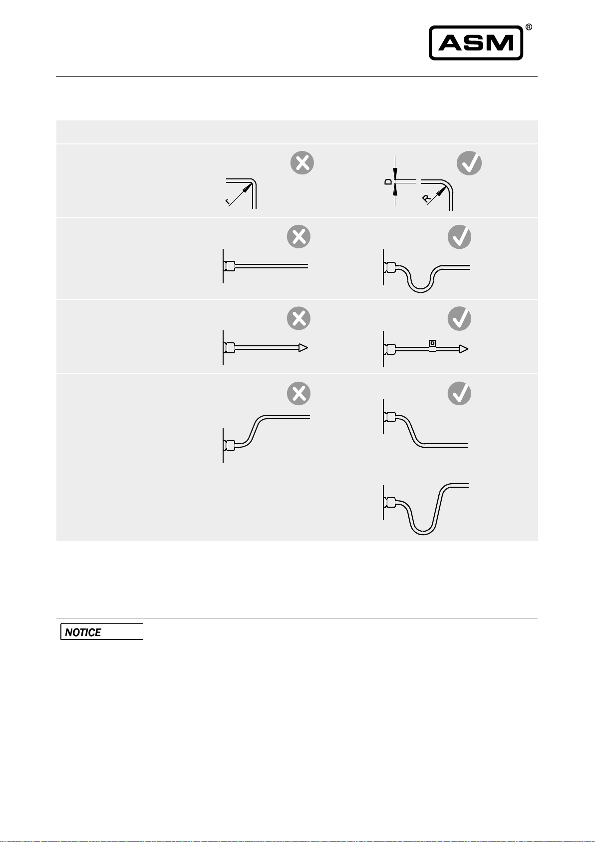
•Mount the sensor without mechanical strain.
•For sensors with shaft use flexible coupling or torque arms to avoid misalignment errors (see page 12
“Couplings”).
Mechanical information for the PRDS27 sensor:
•Mount the sensor on a flat surface.
•Do not deform the sensor housing!
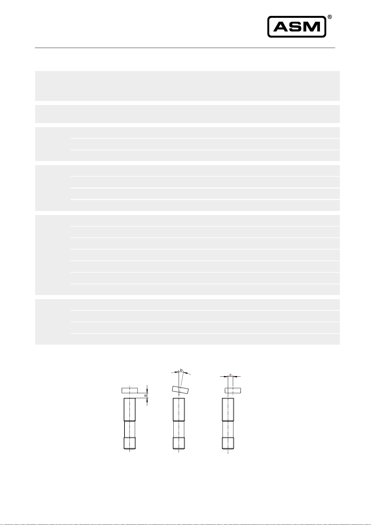
Placement and alignment of the position magnet
For non-contact sensor models air gap and alignment of sensor and position magnet has to be observed. The
linearity will degrade in case of misalignment.
Adjacent magnetic fields or ferromagnetic materials can influence the measurement results of the PRDS
sensors of the posirot®product family. Therefore, the angle sensors and position magnets should be mounted
solely with nonmagnetic / non magnetisable screws and washers.
The angle sensors PRDS1, PRDS2, PRDS3, PRDS5, PRDS6 and PRDS7 are equipped with an integrated
magnetic shield which minimizes the sensitivity against external magnetic fields.
An optional shield plate is available for the angle sensors PRDS27 and PRDS29. It can reduce the effect of
residual magnetizing in case the sensor has to be mounted on a ferromagnetic material.
It is however not possible to exclude the effect of lateral external magnetic fields.
Pos: 20 /Bedienungsanl eitungen/Posirot/PRD S/Elektrischer Anschluss _PRDS@ 8 \mod_1555 488531714_78.docx @ 63431 @ 2 @ 1

posirot®
Magnetic Angle Sensors PRDS-CANOPR, PRDS-J1939R
Version 1.0.0
www.asm-sensor.com
7
3.2 Electrical connection
Damage or destruction of the sensor due to excessive operating voltage or
mounting error
•The applied operating voltage must not exceed the value specified in the data
sheet.
•Operate the sensor only within the limits specified in the data sheet.
•Connection to the power supply only by qualified personnel and in accordance with
the applicable safety regulations for electrical equipment.
•Do not connect or disconnect the sensor under voltage!
Corrosion in the sensor due to moisture penetration
•Use the sensor only according to protection class.
•The mating connector should have the same protection class as the sensor,
otherwise the lower protection class of the mating connector is valid.
•Avoid crossing the dew point.
•Cable outputs must be installed in such a way that no moisture can get into the
cable.
•The protection class of sensors with connector output is valid only if the electrical
plug is connected!
Damage of the sensor cable due to mechanical stress
•Do not twist the M12 connector inserts.
•It is important that the knurled nuts on the connectors are tightened to the correct
torque for each different size of the connector:
•M12-ASM connectors / couplings: 1.0 Nm
•connectors / couplings of other manufacturers: according to manufacturer
instruction.
•Use a torque wrench.
•Do not strain the connection cable.
•A separate strain relief is recommended.
Connector Pin assignment
According to the definitions of the output types contained in the appendix. Observe different color code for
pre-assembled accessory cables. See catalog information for accessories.
Supply voltage
See specification in the data sheet of the sensor. The maximum operating voltage must not be exceeded.
Pos: 21 /######## ### Seitenumbruch #### ############## ############# #### @ 0\mod_13 53584168894_0.d ocx @ 336 @ @ 1

posirot®
Magnetic Angle Sensors PRDS-CANOPR, PRDS-J1939R
8
Version 1.0.0
www.asm-sensor.com
Pos: 22 /Bedienungs anleitungen/Mo duleU niversal/Montage S ensorkabel @ 6\ mod_15196512352 86_78.docx @ 52835 @ @ 1
Installation of the sensor supply cable
incorrect
correct
Admissible bending radius of the
cable must be observed:
R ~ 5 x D
R ~ 10 x D (underwater cable)
Length compensation for the
cable must be observed
A separate cord grip for cable
strain relief is recommended
Observe cable routing in case of
splashing water, water
condensation and humidity
Pos: 23 /Bedienungsanl eitungen/Posirot/PRAS /PR_EMV @ 7\mod_15 26382079171_78.doc x@ 55 995@ @ 1
Electromagnetic Compatibility (EMC)
Electromagnetic compatibility of posirot®magnetic angle sensors is influenced by the sensor wiring.
Possible malfunction of the sensor when used in systems with highly
interference-prone components such as frequency inverters
Recommended wiring:
•Use single shielded sensor cable with twisted pair conductors for power supply
and signal output.
•Connect the cable shield to ground on one side of the control cabinet. Connect
the shield connection over a large area using cable clamps before or at the cable
entry into the control cabinet. When preassembled cables are delivered, the
screen is not connected to the housing on the sensor side.
•Do not install sensor cables close to power conductors such as motor or
contactor control cables (use separate cable ducts for signal and power cables).
•Install the cables in metal cable ducts which are connected to ground.

posirot®
Magnetic Angle Sensors PRDS-CANOPR, PRDS-J1939R
Version 1.0.0
www.asm-sensor.com
9
Pos: 25 /Bedienungsanl eitungen/Posirot/PRD S-CANR-J1939/Ar beitstemperatur_PRD S_2Kanal @ 8\mod_154 9971965465_78. docx@ 6196 7 @2 @ 1
3.3 Operating temperature
posirot® PRDS27
-40 ... +85°C
posirot® PRDS29
-40 ... +85°C
posirot® PRDS1
-40 ... +85°C
posirot® PRDS2
-40 ... +85°C
posirot® PRDS3
-40 ... +85°C
posirot® PRDS5
-40 ... +85°C
posirot® PRDS6
-40 ... +85°C
posirot® PRDS7
-40 ... +85°C
Pos: 26 /######## ### Seitenumbruch #### ############## ############# #### @ 0\mod_13 53584168894_0.d ocx @ 336 @ @ 1

posirot®
Magnetic Angle Sensors PRDS-CANOPR, PRDS-J1939R
10
Version 1.0.0
www.asm-sensor.com
Pos: 27 /Bedienungsanl eitungen/Posirot/PRD S-CANR-J1939/Seit enversatz_Tabelle _PRDS @ 3\mod_145432 1840737_78.docx @ 22326 @ @ 1
Measuring error by misalignment of the position magnet
Sensor
Position
magnet
Air gap
[mm]
(a)
Parallelis
m [°]
(b)
Error by axial misalignment
[°]
(c)
0.2
mm
0.5
mm
1 mm
2 mm
3 mm
4 mm
PRDS1
PRMAG20
0 ... 6.5
0 ... 5
0.15
0.4
0.8
2.2
5.0
–
PRMAG21
0 ... 4
0 ... 5
0.2
0.4
1
3.8
10
–
PRMAG22
0 ... 9.5
0 ... 5
0.1
0.4
1
2.2
4.5
8
PRDS2
PRMAG2-Z-VA
0 ... 9
0 ... 5
0.1
0.2
0.6
1.5
4.5
8.5
PRMAG20
0 ... 6
0 ... 5
0.15
0.4
0.8
2.2
5
–
PRMAG21
0 ... 3.5
0 ... 5
0.2
0.4
1
3.8
10
–
PRMAG22
0 ... 9
0 ... 5
0.1
0.4
1
2.2
4.5
8.0
PRDS5
PRDS6
PRDS7
PRMAG2-Z-(VA)
0 ... 8.5
0 ... 5
0.1
0.2
0.6
1.5
4.5
8.5
PRMAG5-Z-(VA)
0 ... 7.5
0 ... 5
0.1
0.2
0.6
1.5
4.5
8.5
PRMAG6-Z-(VA)
0 ... 7.5
0 ... 5
0.1
0.2
0.6
1.5
4.5
8.5
PRMAG7-Z-VA
0 ... 7.5
0 ... 5
0.1
0.2
0.6
1.5
4.5
8.5
PRMAG20
0 ... 5.5
0 ... 5
0.15
0.4
0.8
2.2
5
–
PRMAG21
0 ... 3
0 ... 5
0.2
0.4
1
3.8
10
–
PRMAG22
0 ... 8.5
0 ... 5
0.1
0.4
1
2.2
4.5
8
PRDS27
PRDS29
PRMAG20
0 ... 7.5
0 ... 5
0.1
0.3
0.7
2
4.6
–
PRMAG21
0 ... 2.5
0 ... 5
0.15
0.3
0.9
3.6
9.6
–
PRMAG22
0 ... 10.5
0 ... 5
0
0
0.7
1.5
3.8
7
PRMAG-M10
0 ... 3.5
0 ... 5
0.1
0.1
0.5
2
7
–
Pos: 28 /######## ### Seitenumbruch # ############## ############## ###### @ 0\mod_13 53584168894_0.d ocx @ 336 @ @ 1

posirot®
Magnetic Angle Sensors PRDS-CANOPR, PRDS-J1939R
Version 1.0.0
www.asm-sensor.com
11
Pos: 29 /Bedienungsanl eitungen/Posirot/PRD S-CANR-J1939/Anz ugsmomente CANR @ 3\mo d_145432308002 4_78.docx @ 22338 @ @ 1
Torque for fixing screws
The specified torques and mounting methods are general recommendations and can differ according to
application and operating conditions.
Model
Mounting method
Material
Torque [Nm]
PRDS1
M12x1
-
2.5
PRDS2, PRDS3
M2,5 screws for mounting brackets
-
0.8
PRDS3
M3 screws for mounting flange
-
1.2
PRDS27, PRDS29
M4
-
1
PRDS5
M8
steel
<10
PRDS6
M6
steel
<6
PRDS7
M6
steel
<6
Pos: 30 /######## ### Seitenumbruch #### ############## ############# #### @ 0\mod_13 53584168894_0.d ocx @ 336 @ @ 1

posirot®
Magnetic Angle Sensors PRDS-CANOPR, PRDS-J1939R
12
Version 1.0.0
www.asm-sensor.com
Pos: 31 /Bedienungsanl eitungen/Posirot/PRAS /Kupplungen @ 6\mod_ 1519989466136_78.d ocx @ 52963 @ 4@ 1
Couplings
Model MK4
Rated torque
2 Nm
Total length (inserted)
37 mm
Axial misalignment (a)
< 0.7 mm
Lateral misalignment (b)
< 0.25 mm
Angular misalignment (c)
< 2°
Dimensions in mm [inch]
Order code
A
B
MK4-37-6-6
Ø6H7 [.236 +.0005]
Ø6H7 [.236 +.0005]
MK4-37-6-10
Ø6H7 [.236 +.0005]
Ø10H7 [.394 +.0006]
MK4-37-6-12
Ø6H7 [.236 +.0005]
Ø12H7 [.472 +.0007]
Pos: 32 /######## ### Seitenumbruch #### ############## ############# #### @ 0\mod_13 53584168894_0.d ocx @ 336 @ @ 1

posirot®
Magnetic Angle Sensors PRDS-CANOPR, PRDS-J1939R
Version 1.0.0
www.asm-sensor.com
13
Pos: 33 /Bedienungsanl eitungen/Posirot/PRD S-CANR-J1939/R eferenzposition UE @ 3\mod_1 454324502621_78.d ocx@ 2 2356@ @ 1
Reference position
Pos: 34 /Bedienungsanl eitungen/Posirot/Refer enzposition/pras2_re f@ 3 \mod_1454400016 042_78.docx @ 22519 @ @ 1
PRDS2 with cable output PRDS2 with connector M12 axial PRDS2 with connector M12 radial
A –Marking
Pos: 35 /######## ### Seitenumbruch #### ############## ############# #### @ 0\mod_13 53584168894_0.d ocx @ 336 @ @ 1

posirot®
Magnetic Angle Sensors PRDS-CANOPR, PRDS-J1939R
14
Version 1.0.0
www.asm-sensor.com
Pos: 36 /Bedienungsanl eitungen/Posirot/Refer enzposition/pras3_re f@ 3 \mod_1454400760 762_78.docx @ 22525 @ @ 1
PRDS3 with shaft and hollow shaft
A –Flat area
B –Marking
C –Marking (back side)
Allowable shaft load:
100 N axial, 100 N radial
Pos: 37 /Bedienungsanl eitungen/Posirot/Refer enzposition/pras5_re f@ 3 \mod_1454401060 593_78.docx @ 22531 @ @ 1
PRDS5 with connector M12 axial, radial
A –Marking
Pos: 38 /######## ### Seitenumbruch # ############## ############## ###### @ 0\mod_13 53584168894_0.d ocx @ 336 @ @ 1

posirot®
Magnetic Angle Sensors PRDS-CANOPR, PRDS-J1939R
Version 1.0.0
www.asm-sensor.com
15
Pos: 39 /Bedienungsanl eitungen/Posirot/Refer enzposition/pras27 _ref@ 3\ mod_145440299 0244_78.docx @ 22545 @ @ 1
PRDS27/PRDS29
Mounting with strain relief
A –Marking
B –Strain relief
Pos: 40 /######## ### Seitenumbruch #### ############## ############# #### @ 0\mod_13 53584168894_0.d ocx @ 336 @ @ 1

posirot®
Magnetic Angle Sensors PRDS-CANOPR, PRDS-J1939R
16
Version 1.0.0
www.asm-sensor.com
Pos: 41 /Bedienungs anleitungen/Mo duleU niversal/Überschrift en/Instandh altung und Entsorgung U E@ 6 \mod_150763 0731526_78.docx @ 4 8417 @ 1 @ 1
4 Maintenance and disposal
Pos: 42 /Bedienungsanl eitungen/Posirot/PRAS /Instandhaltung _Wartung @ 2\mod_144013 9535202_78.docx @ 19854 @ 2 @ 1
4.1 Maintenance and repair
Opening all the posirot® sensors will cause damage and void the warranty
•Do not open the sensor.
•We strongly advise against repair attempts. Any repairs not carried out by ASM
will invalidate the warranty. Damaged sensors must be shut down immediately,
please contact ASM.
Maintenance interval
Proper maintenance comprises the visual examination of parts (e.g. integrity of housing, connectors and
cables). Maintenance intervals depend on the specific application and should be defined by the user in
dependence of operating conditions.
Check sensor regularly for possible damage. The following maintenance steps are recommended:
Inspection of …
Measures
Integrity of housing
Remove sensor from service and send it to ASM for repair
Integrity of cables, connectors
Damaged parts: remove sensor from service and replace damaged
parts resp. send sensor to ASM for repair
Mounting elements
Loose mounting parts: mounting elements must be tightened with
recommended torque. Provide screw locks if necessary
Visual check of shaft sealing
Damaged shaft sealing:
Remove sensor from service and send it to ASM for repair
Pos: 43 /Bedienungsanl eitungen/Posiwire/W S_Kalibrierung @ 4\mod _1491566471251_78. docx@ 3 8399 @ @ 1
Calibration
The recommended calibration interval is 1 year.
Test protocol and traceable calibration certificate (ISO9001 / ISO10012) is available on request.
Pos: 44 /Bedienungsanl eitungen/Posiwire/W S_Entsorgung @ 6\mod_15 07649730932_78. docx @ 48485 @ 2@ 1
4.2 Disposal
Disposal according to applicable government regulations.
Pos: 45 /######## ### Seitenumbruch #### ############## ############# #### @ 0\mod_13 53584168894_0 .docx @ 336 @ @ 1

posirot®
Magnetic Angle Sensors PRDS-CANOPR, PRDS-J1939R
Version 1.0.0
www.asm-sensor.com
17
Pos: 46 /Ausgangs arten/Posirot/Spezifi kation Ausgangsart enU E @ 1\mod_1401 977308430_78.d ocx @ 10050 @ 1 @ 1
5 Output specification
Pos: 47 /Ausgangsarten/Po sirot/CANOP/Digit al-Ausgänge UE @ 6\mod_15 19380539211_78.doc x @ 52666@ @ 1
Digital output
Pos: 48 /Ausgangsarten/Po sirot/CANOP/CAN openR@ 2 \mod_1447414 115308_78.docx @ 20677 @ @ 1
CANOPR
CANopen
CAN Specification
ISO 11898, Basic and Full CAN 2.0 B
Communication profile
CANopen CiA 301 V 4.02, Slave
Device profile
Encoder CiA 406 V 3.2
Configuration services
Layer Setting Service (LSS), CiA Draft
Standard 305 (transmission rate, node id)
Error Control
Node Guarding, Heartbeat, Emergency
Message
Node ID
Default: 127 and 126; programmable via LSS
or SDO
PDO
3 TxPDO, 0 RxPDO, static mapping
PDO Modes
Event-/Time triggered, Remote-request,
Sync cyclic/acyclic
SDO
1 server, 0 Client
CAM
8 cams
Certified
Yes
Transmission rates
50 kBaud to 1 MBaud, default: 125 kBaud;
programmable via LSS or SDO
Bus connection
M12 connector, 5 pin
Integrated bus terminating
resistor
adjustable by the customer
Bus, galvanic isolated
No
Specifications
Excitation voltage
8 ... 36 V DC
Excitation current
40 mA typical at 24 V DC
80 mA typical at 12 V DC, 120 mA max.
Measuring rate
1 kHz (asynchronous)
Stability (temperature)
±50 x 10-6/°C f.s. (typical)
Repeatability
1 LSB
Operating temperature
See specification of the respective sensor
Protection
Reverse polarity, short circuit
Dielectric strength
1 kV (V AC, 50 Hz, 1 min.)
EMC
DIN EN 61326-1:2013

posirot®
Magnetic Angle Sensors PRDS-CANOPR, PRDS-J1939R
18
Version 1.0.0
www.asm-sensor.com
Signal wiring
Connector M12, 5 pin
View to the sensor
connector
Output signals
Connector pin no.
Cable color
Shield
1
brown
Excitation +
2
white
GND
3
blue
CAN-H
4
black
CAN-L
5
grey
Pos: 49 /Bedienungs anleitungen/Positap e/CANopen_s pec_WS_WB/CANo p_setup @ 7\mod _1527003732700 _78.docx @ 56023 @ @ 1
CANopen –Set up (MCANOP)
Download
•A detailed specification of this interface can be downloaded from the ASM website:
www.asm-sensor.com/en/downloads.html > Configuration files
Risk of injury by unexpected machine movement
•Change parameters only when machine is in a safe condition!
•Changing parameters may cause unexpected machine movement.
•Changing parameters may influence dependent parameters e.g. changing the
resolution may have influence on position of CAM switches.
•Precautions have to be taken to avoid damage to human and machine parts!
Pos: 50 /######## ### Seitenumbruch # ############## ############## ###### @ 0\mod_13 53584168894_0.d ocx @ 336 @ @ 1

posirot®
Magnetic Angle Sensors PRDS-CANOPR, PRDS-J1939R
Version 1.0.0
www.asm-sensor.com
19
Pos: 51 /Ausgangsarten/Po sirot/CAN SAE J1939/CAN SAE J1 939R @ 2\mod_14474143 63764_78.docx @ 20683 @ @ 1
CANJ1939R
CAN SAE J1939
CAN Specification
ISO 11898, Basic and Full CAN 2.0 B
Transceiver
24V-compliant, not isolated
Communication profile
SAE J1939
Baud Rate
250 kbit/s
Internal termination resistor
Adjustable by the customer
Address
Default 247d and 246d, configurable
NAME Fields
Arbitrary address capable
1
Yes
Industry group
0
Global
Vehicle system
7Fh (127d)
Non specific
Vehicle system instance
0
Function
FFh (255d)
Non specific
Function instance
0
ECU instance
0
Manufacturer
145h (325d)
Manufacturer ID
Identity number
0nnn
Serial number 21 bit
Parameter Group
Numbers (PGN)
Configuration data
PGN EF00h
Proprietary-A
(PDU1 peer-to-peer)
Process data
PGN FFnnh
Proprietary-B
(PDU2 broadcast);
nn Group Extension (PS)
configurable
Specifications
Excitation voltage
8 ... 36 V DC
Excitation current
40 mA typical at 24 V DC
80 mA typical at 12 V DC
120 mA max.
Measuring rate
1 kHz (asynchronous)
Stability (temperature)
±50 x 10-6/°C f.s. (typical)
Repeatability
1 LSB
Operating temperature
See specification of the respective sensor
Protection
Reverse polarity, short circuit
Dielectric strength
1 kV (V AC, 50 Hz, 1 min.)
EMV
DIN EN 61326-1:2013

posirot®
Magnetic Angle Sensors PRDS-CANOPR, PRDS-J1939R
20
Version 1.0.0
www.asm-sensor.com
Signal wiring
Connector M12, 5 pin
View to the sensor
connector
Output signals
Connector pin no.
Cable color
Shield
1
brown
Excitation +
2
white
GND
3
blue
CAN-H
4
black
CAN-L
5
grey
Pos: 52 /Bedienungs anleitungen/Positap e/SAE J1939/SAE J 1939_setup @ 7\ mod_1527060993 387_78.docx @ 56033 @ @ 1
SAE J1939 –Set up (MCANJ1939)
Download
•A detailed specification of this interface can be downloaded from the ASM website:
www.asm-sensor.com/en/downloads.html > Configuration files
Risk of injury due to unexpected machine movement
•Change parameters only when machine is in a safe condition!
•Changing parameters may cause unexpected machine movement.
•Changing parameters may influence dependent parameters e.g. changing the
resolution may have influence on position of CAM switches.
•Precautions have to be taken to avoid damage to human and machine parts!
Pos: 53 /Bedienungsanl eitungen/Positape/C ANopen_spec_WS_ WB/CAN bus wiring @ 4\mod_149 1214602548_78.doc x@ 372 01@ @ 1
CAN-Bus wiring
Connect the device by a T-connector to the CAN trunk line. Total length of stubs should be minimized. Do
not use single stub lines longer than 0.5 m. Connect terminating resistors 120 Ohm at both ends of the
trunk line.
Termination resistor
T piece
CAN cable
sensor
Pos: 54 /######## ### Seitenumbruch #### ############## ############# #### @ 0\mod_13 53584168894_0.d ocx @ 336 @ @ 1
This manual suits for next models
1
Table of contents
Other ASM Accessories manuals

ASM
ASM Posihall PH36 Owner's manual

ASM
ASM POSITAPE WB Series User manual

ASM
ASM posiwire WS10EX User manual

ASM
ASM posirot PRAS2EX User manual

ASM
ASM posirot PRAS Series User manual

ASM
ASM posirot PRAS Series User manual

ASM
ASM positape WBT Series User manual

ASM
ASM posirot PRAS Series User manual

ASM
ASM posiwire User manual

ASM
ASM positilt PTM Series User manual