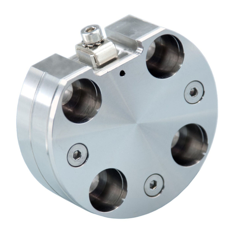
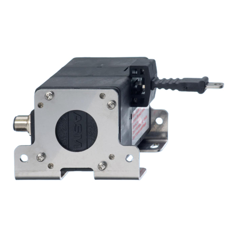
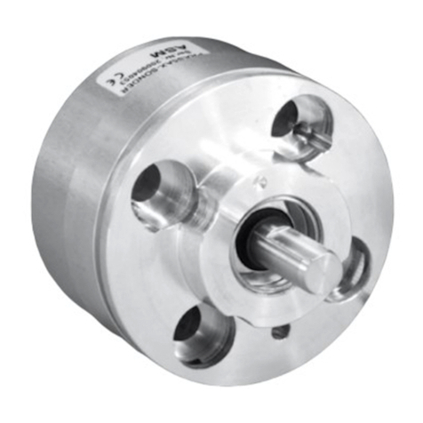
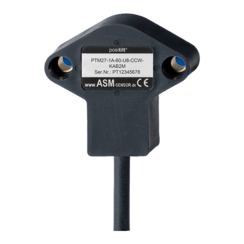
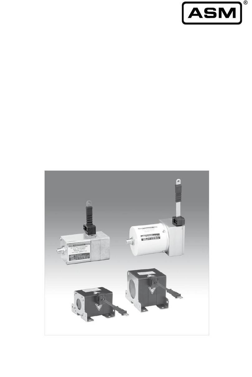
ASM Posihall PH36 Owner's manual

POSIHALL®
Magnetic Multiturn
Angle Sensors
Installation and operation manual
Please read carefully before installation and operation!

2 MAN-PH-E-16 © by ASM GmbH
www.asm-sensor.com / USA: www.asmsensors.com
POSIHALL®
Contents
Contents Safety instructions........................................................................ 3
Intended use.................................................................................. 4
Maintenance and service.............................................................. 4
Description..................................................................................... 4
Delivery / shipment....................................................................... 5
Mounting of PH36.......................................................................... 6
Mounting plate PRPT-BPL1...................................................... 7
Mounting plate PRPT-BPL 2 .................................................... 7
Mounting plate PRPT-BPL 3 .................................................... 8
Mounting clamp/bracket........................................................... 9
Electrical connection...................................................................10
Characteristics for multiturn angle sensors..............................11
Calibration.................................................................................... 12
Electromagnetic compatibility (EMC)........................................ 12
Repair and disposal.................................................................... 12
Output specifications................................................................. 13
Analog output..........................................................................13
Analog output, programmable................................................ 15
Analog output, redundant........................................................17
Digital output MSSI................................................................. 19
Digital output CANopen...........................................................20
Digital output CAN SAE J1939............................................... 31
Accesories - Connector cables.................................................. 36
Reliability Characteristics...........................................................40
Declaration of conformity......................................................... 41

© by ASM GmbH MAN-PH-E-16 3
www.asm-sensor.com / USA: www.asmsensors.com
Safety
instructions
If total failure or malfunction of the sensor can cause danger or
injury to the operator or damage to the machinery or equipment
it is recommended that additional safety measures should be
incorporated into the system.
Any alteration, reconstruction or extension of the sensor is not
allowed.
Sensor must be operated only within values specied in the
datasheet.
Connection to power supply must be performed in accordance
with safety instructions for electrical facilities and performed
only by trained staff.
Do not connect / disconnect the sensor under tension.
Disregard of this advice can lead to malfunctions, damage to
property or personal injury and releases the manufacturer from
product liability.
POSIHALL®
Safety instructions
Explanation of used
safety signs and
signal words
WARNING, Risk of Injury:
Indicates a potentially hazardous situation, which,
if not avoided, could result in serious injury or
property damage.
WARNING, Risk of Personal Injury or Death:
Indicates a situation that can result in serious
personal injury or death if not properly avoided.
DANGER
WARNING, Risk of Personal Injury or Death:
Indicates a situation that can result in moderate
personal injury or death if not properly avoided.
WARNING
WARNING, Risk of Personal Injury:
Indicates a situation that can result in minor personal
injury if not properly avoided.
CAUTION
WARNING, Risk of Property Damage:
Indicates a situation that can result in minor to major
property damage if not properly avoided.
NOTICE

4 MAN-PH-E-16 © by ASM GmbH
www.asm-sensor.com / USA: www.asmsensors.com
POSIHALL®
Safety instructions
Integrity of housing,
connector, cable
Mounting
elements
Visual check of
shaft sealing
PH36 X X X
PH58 X X X
PH68 / PH68R X X X
Measures Damaged parts: Put
sensor out of service and
replace damaged parts
resp. send sensor to ASM
for repair
Loose mounting parts:
Screw tight mounting parts
with recommended torque,
if applicable use bolt
adhesive
Damaged shaft sealing:
Put sensor out of ser-
vice and send it to ASM
for repair
Intended use
Unintended use
Maintenance and
service
• In order to avoid risk of injury and improper handling the customer
is not allowed to repair the sensor. No warranty or liability will be
granted for opened sensors.
• Damaged sensors must be shut down immediately and sent to the
factory for repair.
Proper maintenance comprises the visual examination of parts (e.g. inte-
grity of housing, connectors and cables). Maintenance intervals depend on
thespecicapplicationandshouldbedenedbytheuserindependence
of operating conditions.
The following maintenance steps are recommended:
Maintenance-
interval
The intended use is when the sensor is used in the properly rated ambient
atmospheric and technical conditions for which the sensor is designated.
Theunintendeduseiswhenthesensorisusedoutsideitsspeciedtechnical
and ambient atmospheric conditions or when improperly mounted.
Deinstallation Disconnectelectricalconnections.Loosenxingscrews.
Disposal Disposal according to applicable government regulations.
Do not open the sensor!
The maximum operating voltage may not exceed the limits specied
in the respective data sheet!
• Danger of injury! Danger of damage to or destruction of the sensor!
Avoid shock and vibration to the sensor!
• Danger of damage to or destruction of the sensor!
Safety
instructions

© by ASM GmbH MAN-PH-E-16 5
www.asm-sensor.com / USA: www.asmsensors.com
POSIHALL®
Delivery / shipment
Delivery /
shipment
Shipment damages Check sensor immediately for ship-
ping damage.
In case of any damage or equipment not operating appropriately, please
contact supplier or ASM GmbH Moosinning. To avoid shipment damages,
use original packing for further shipment.
Return consignment for calibration or repair: only with the RMA number
(Return Material Authorization). Please contact ASM and request the RMA
number:
ASM Automation Sensorik
Messtechnik GmbH
Service&Repair
Am Bleichbach 18-24
85452 Moosinning
Germany
Tel. +49 8123 986-0
Fax +49 8123 986-500
service@asm-sensor.de
www.asm-sensor.com
Return
consignment

6 MAN-PH-E-16 © by ASM GmbH
www.asm-sensor.com / USA: www.asmsensors.com
POSIHALL®
Description
Installation
WARNING
The purpose of position sensors is to transform position of a linear and
guided movement into an electrical signal. Specications of measuring
range,environment,handlingandconnectionsasspeciedinthecatalog,
must be followed.
The catalog is part of this instruction manual. If the catalog is not available
it may be requested by stating the respective model number.
Description
Adjacent magnetic elds or ferromagnetic materials can inuence the
measurement results of the PH sensors of the POSIHALL®product family.
Therefore the angle sensors should be mounted solely with nonmagnetic /
non magnetisable screws and washers.
The POSIHALL® multiturn angle sensors PH36, PH58 and PH68, PH68R
are equipped with an integrated magnetic shield which minimizes the
sensitivityagainstexternalmagneticelds
The POSIHALL® multiturn angle sensors can be mounted with clamping
angeorsynchroangedependingonmodel,andthereforeofferuniversal
mounting possibilities.
PH36 Synchro flange for the installation with mounting
clamps or mounting brackets and M3 thread at the
front
PH58 Clamping flange and M3 / M4 thread at the front
Synchro flange and M4 thread at the front
PH68/PH68R Synchro flange and M4 thread at the front

33 [1.299]Ø
40 [1.575]
40[1.575]
42[1.654]
5,5[.217]
5[.197]
4 [.157]
55 [2.165]
3x M2,5
4[.157]
90°
110°
3x M4
48 [1.890]
33 [1.299]Ø
42[1.654]
4 [.157]
55 [2.165]
3x M2,5
4[.157]
90°
110°
3x M4
48 [1.890]
© by ASM GmbH MAN-PH-E-16 7
www.asm-sensor.com / USA: www.asmsensors.com
Mounting plate
PRPT-BPL1
(screw mounting)
Mounting plate
PRPT-BPL2
(welding assembly)
Dimensions in mm [inch]
Dimensions informative only.
For guaranteed dimensions consult factory.
In combination with the
mounting clamps
PRPT-BFS1 (3 x M2.5)
or
in combination with the
mounting bracket
PRPT-BFS2 (3 x M4).
Weight approx. 30 g.
In combination with the
mounting clamps
PRPT-BFS1 (3 x M2.5)
or
in combination with the
mounting bracket
PRPT-BFS2 (3 x M4).
Weight approx. 30 g
POSIHALL®
Mounting of PH36
Mounting plates (only for PH36)

PRPT-BPL1
+
PRPT-BFS1
PRPT-BPL2
+
PRPT-BFS1
PRPT-BPL2
+
PRPT-BFS2
PRPT-BPL1
+
PRPT-BFS2
8 MAN-PH-E-16 © by ASM GmbH
www.asm-sensor.com / USA: www.asmsensors.com
Mounting possibilities
PH36
Mounting plate
PRPT-BPL3
(frontal mounting)
Weight approx. 30 g
POSIHALL®
Mounting of PH36
Dimensions in mm [inch]
Dimensions informative only.
For guaranteed dimensions consult factory.
Mounting plate (only for PH36)

© by ASM GmbH MAN-PH-E-16 9
www.asm-sensor.com / USA: www.asmsensors.com
POSIHALL®
Mounting of PH36
Mounting clamp/bracket
for PH36
Mounting clamp BFS1 Mounting bracket BFS2
• Prevent the sensor shaft from binding.
• Use exible coupling or torque arms to avoid misalignment
errors.
• Observe the specied torques for xing screws (see table p. 10)
• Avoid impact or shocks on the shaft and the shaft coupling!
Mechanical
information

10 MAN-PH-E-16 © by ASM GmbH
www.asm-sensor.com / USA: www.asmsensors.com
POSIHALL®
Electrical installation
Torque for xing screws
• Thespeciedtorquesandmountingmethodsaregeneralrecommenda-
tions.
• Thespeciedtorquescandifferaccordingtoapplicationandoperating
conditions.
• The user is responsible for the appropriate torque, since ASM does not
know the operational conditions of the application.
Output Value range 50% value of output signal
U2 0.5 ... 10 V 5.25 V
U6 0.5 ... 4.5 V 2.5 V
U8 0.5 ... 4.5 V 2.5 V
I1 4 ... 20 mA 12 mA
Mounting
Torque Mounting methos Material Torque [Nm]
M2.5 screws for mounting brackets Aluminium 0.8
M3screwsformountingange Aluminium 1.0
Screws M4 Aluminium 1.8
Observe different color code for pre-assembled accessory cables - refer
to accessories pages.
The protection class of sensors with connector output is valid only if the
electrical plug is connected!
Do not twist the M12 connector insert.
Cable outputs must be installed in such a way that no moisture can get
into the cable. Crossing the dew point must be avoided.
Do not strain the connection cable.
A separate cord grip is recommended.
For wiring of connector or cable outlet as well as supply voltage and cur-
rent consumption see from page 13.
Cable screen has to be connected to protective earth.
Electrical installation
Supply voltage,
current
consumption
NOTICE

A
A
A
A
© by ASM GmbH MAN-PH-E-16 11
www.asm-sensor.com / USA: www.asmsensors.com
Clockwise increasing signal (CW), view to sensor measuring area/shaft
Counterclockwise increasing signal (CCW), view to sensor measuring area/shaft
Example for angle range 90°
Example for angle range 360°
POSIHALL®
Characteristics for multiturn angle sensors
A = angle position at delivery

12 MAN-PH-E-16 © by ASM GmbH
www.asm-sensor.com / USA: www.asmsensors.com
POSIHALL®
Calibration, EMC
Calibration
(ISO9001)
Electromagnetic
Compatibility
(EMC)
Repair and
disposal
The recommended calibration interval is 1 year.
Testprotocolandtraceablecalibrationcerticate(ISO9001)isavailableon
request.
The electromagnetic compatibility depends on wiring practice. Recommen-
ded wiring:
• Use shielded twisted pair sensor cable.
• Ground shield single ended at switch cabinet. Connect shield directly
before or at cable inlet of switch cabinet by low impedance ground ca-
ble bond. On delivery of preassembled sensor cables the shield is not
connected to the sensor housing.
• Keep sensor signal well separated from power wiring e.g. AC wiring,
motor or relay. Use separate conduit or ducts for each.
If application includes highly electromagnetic interference emitting equip-
ment like switch converter drives additional measures are recommended:
• Use a twisted pair cable, shielded per pair and common.
• Use shielded conduits or ducts connected to ground potential.
Sensors and accessories have to be repaired and adjusted at ASM head-
quarters in Moosinning, Germany.
In order to avoid risk of injury and improper handling do not try to repair. No
warranty or liability will be granted for opened sensors.
Send metal parts for recycling!
Disposal according to applicable government regulations.
WARNING

© by ASM GmbH MAN-PH-E-16 13
www.asm-sensor.com / USA: www.asmsensors.com
I1
Current output
4 ... 20 mA, 3 wire
Excitation voltage 8 ... 36 V DC
Excitation current typical 36 mA at 24 V DC
typical 70 mA at 12 V DC
max. 120 mA
Load RL500 Ωmax.
Output current 4 ... 20 mA
Measuring rate 1 kHz standard
Stability (temperature) ±50 x 10-6/°C f.s. (typical)
Protection Reverse polarity, short circuit
Operating temperature -40 ... +85 °C
EMC DIN EN 61326-1:2013
U8
Voltage output
0.5 ... 4,5 V
Excitation voltage 8 ... 36 V DC
Excitation current typical 17 mA at 24 V DC
typical 32 mA at 12 V DC
max. 50 mA
Output voltage 0,5 ... 4,5 V DC
Output current 2 mA max.
Measuring rate 1 kHz standard
Stability (temperature) ±50 x 10-6/°C f.s. (typical)
Protection Reverse polarity, short circuit
Operating temperature -40 ... +85 °C
EMC DIN EN 61326-1:2013
U2
Voltage output
0.5 ... 10 V
Excitation voltage 8 ... 36 V DC
Excitation current typical 20 mA at 24 V DC
typical 38 mA at 12 V DC
max. 50 mA
Output voltage 0,5 ... 10 V DC
Output current 2 mA max.
Measuring rate 1 kHz standard
Stability (temperature) ±50 x 10-6/°C f.s. (typical)
Protection Reverse polarity, short circuit
Operating temperature -40 ... +85 °C
EMC DIN EN 61326-1:2013
POSIHALL®
Analog output
U6
Voltage output
0,5 ... 4,5 V
Excitation voltage 5 V DC ± 5%
Excitation current typical 140 mA
Output voltage 0,5 ... 4,5 V DC
Output current 2 mA max.
Measuring rate 1 kHz standard
Stability (temperature) ±50 x 10-6/°C f.s. (typical)
Protection Reverse polarity, short circuit
Operating temperature -40 ... +85 °C
EMC DIN EN 61326-1:2013

U2
U6
U8
I1
14 MAN-PH-E-16 © by ASM GmbH
www.asm-sensor.com / USA: www.asmsensors.com
Output signals
Excitation +
GND
Signal +
Signal Wiring Signal Plug connection Cable connection
Excitation + 1 brown
Signal 2 white
GND 3 blue
Do not connect! 4 black
Do not connect! 5 grey
Connection
View to the sensor
connector
A-Codification
POSIHALL®
Analog output

© by ASM GmbH MAN-PH-E-16 15
www.asm-sensor.com / USA: www.asmsensors.com
POSIHALL®
Analog output, programmable
I1/PMU, I1/PMZ
Current output
4 ... 20 mA, 3 wire
Excitation voltage 8 ... 36 V DC
Excitation current typical 36 mA at 24 V DC
typical 70 mA at 12 V DC
max. 120 mA
Load RL500 Ωmax.
Output current 4 ... 20 mA
Measuring rate 1 kHz standard
Stability (temperature) ±50 x 10-6/°C f.s. (typical)
Protection Reverse polarity, short circuit
Operating temperature -40 ... +85 °C
EMC DIN EN 61326-1:2013
U8/PMU, U8/PMZ
Voltage output
0.5 ... 4,5 V
Excitation voltage 8 ... 36 V DC
Excitation current typical 17 mA at 24 V DC
typical 32 mA at 12 V DC
max. 50 mA
Output voltage 0,5 ... 4,5 V DC
Output current 2 mA max.
Measuring rate 1 kHz standard
Stability (temperature) ±50 x 10-6/°C f.s. (typical)
Protection Reverse polarity, short circuit
Operating temperature -40 ... +85 °C
EMC DIN EN 61326-1:2013
U2/PMU, U2/PMZ
Voltage output
0.5 ... 10 V
Excitation voltage 8 ... 36 V DC
Excitation current typical 20 mA at 24 V DC
typical 38 mA at 12 V DC
max. 50 mA
Output voltage 0,5 ... 10 V DC
Output current 2 mA max.
Measuring rate 1 kHz standard
Stability (temperature) ±50 x 10-6/°C f.s. (typical)
Protection Reverse polarity, short circuit
Operating temperature -40 ... +85 °C
EMC DIN EN 61326-1:2013
U6/PMU, U6/PMZ
Voltage output
0,5 ... 4,5 V
Excitation voltage 5 V DC ± 5%
Excitation current typical 140 mA
Output voltage 0,5 ... 4,5 V DC
Output current 2 mA max.
Measuring rate 1 kHz standard
Stability (temperature) ±50 x 10-6/°C f.s. (typical)
Protection Reverse polarity, short circuit
Operating temperature -40 ... +85 °C
EMC DIN EN 61326-1:2013

U2/PMU/PMZ
U6/PMU/PMZ
U8/PMU/PMZ
I1/PMU/PMZ
16 MAN-PH-E-16 © by ASM GmbH
www.asm-sensor.com / USA: www.asmsensors.com
Output signals
POSIHALL®
Analog output, programmable
)
Signal wiring Signal Connector
pin no. Cable color
Excitation + 1 brown
Signal 2 white
GND 3 blue
Do not connect! 4 black
SPAN/ZERO 5 grey
View to sensor
connector
Option -PMU
Programming of the start and end value by the customer
Teach-In of start and end value for the options U2/PMU, I1/PMU, U8/PMU is provided by a binary si-
gnal SPAN/ZERO. At the start position connect signal SPAN/ZERO for a period of 2 … 3 seconds to
GND via push button. At the end position connect signal SPAN/ZERO for a period of 5 … 6 seconds
to GND via a push button. The teached positions will be stored non-volatile.
To reset the sensor to factory default signal ZERO/END must be connected to ground while powering
up the sensor for 2 … 3 seconds.
A-Codification
Option -PMZ
Programming of the start value by the customer
Programming of the start value of the output range for the outputs U2/U8 and I1 is provided by a pro-
gramming signal ZERO available at the connector. This Signal ZERO must be connected with GND
via a push button, and then the position magnet of the sensor must be moved to the start resp. the
end position. Pushing the button between 1 and 4 seconds sets the actual position as start position,
pushing the button more than 5 seconds sets the actual position as end position. The values will be
stored and are available after switching off the sensor.
To reset the sensor to the factory values the button must be pushed when the sensor is switched on.
Excitation +
GND
Signal +

© by ASM GmbH MAN-PH-E-16 17
www.asm-sensor.com / USA: www.asmsensors.com
POSIHALL®
Analog output, redundant
I1R
Current output
4 ... 20 mA, 3 wire
Excitation voltage 8 ... 36 V DC
Excitation current typical 36 mA at 24 V DC
typical 70 mA at 12 V DC
max. 120 mA per channel
Load RL500 Ωmax.
Output current 4 ... 20 mA
Measuring rate 1 kHz standard
Stability (temperature) ±50 x 10-6/°C f.s. (typical)
Protection Reverse polarity, short circuit
Operating temperature -40 ... +85 °C
EMC DIN EN 61326-1:2013
U8R
Voltage output
0.5 ... 4,5 V
Excitation voltage 8 ... 36 V DC
Excitation current typical 17 mA at 24 V DC
typical 32 mA at 12 V DC
max. 50 mA per channel
Output voltage 0,5 ... 4,5 V DC
Output current 2 mA max.
Measuring rate 1 kHz standard
Stability (temperature) ±50 x 10-6/°C f.s. (typical)
Protection Reverse polarity, short circuit
Operating temperature -40 ... +85 °C
EMC DIN EN 61326-1:2013
U2R
Voltage output
0.5 ... 10 V
Excitation voltage 8 ... 36 V DC
Excitation current typical 20 mA at 24 V DC
typical 38 mA at 12 V DC
max. 50 mA per channel
Output voltage 0,5 ... 10 V DC
Output current 2 mA max.
Measuring rate 1 kHz standard
Stability (temperature) ±50 x 10-6/°C f.s. (typical)
Protection Reverse polarity, short circuit
Operating temperature -40 ... +85 °C
EMC DIN EN 61326-1:2013
U6R
Voltage output
0,5 ... 4,5 V
Excitation voltage 5 V DC ± 5%
Excitation current typical 140 mA per channel
Output voltage 0,5 ... 4,5 V DC
Output current 2 mA max.
Measuring rate 1 kHz standard
Stability (temperature) ±50 x 10-6/°C f.s. (typical)
Protection Reverse polarity, short circuit
Operating temperature -40 ... +85 °C
EMC DIN EN 61326-1:2013

U2R
U6R
U8R
I1R
18 MAN-PH-E-16 © by ASM GmbH
www.asm-sensor.com / USA: www.asmsensors.com
Excitation +
GND
Signal +
Excitation +
GND
Signal +
Do not connect
Do not connect
Output signals
POSIHALL®
Analog output, redundant
Signal wiring,
redundant version
with 2 channels
and 1 connector
Channel Signal Connector
M12, 8 pins
Cable
connection
1 Excitation + 1 white
1 Signal 2 brown
1 GND 3 green
1 Do not connect! 4 yellow
2 Excitation + 5 grey
2 Signal 6 pink
2 GND 7 blue
2 Do not connect! 8 red
View to sensor
connector
A-Codification

© by ASM GmbH MAN-PH-E-16 19
www.asm-sensor.com / USA: www.asmsensors.com
MSSI
Synchronous serial SSI
Interface EIA RS-422
Excitation voltage 8 ... 36 V DC
Excitation current typ. 19 mA at 24 V DC
typ. 35 mA at 12 V DC
max. 80 mA
Clock frequency 100 kHz ... 500 kHz
Code Gray-Code, continuous progression
Delay between pulse trains 20 µs min.
Stability (temperature) ±50 x 10-6 / °C f.s. typical
Operating temperature -40 ... +85 °C
Protection Short circuit
EMC DIN EN 61326-1:2013
POSIHALL®
Digital output MSSI
DATA
DATA
CLOCK
CLOCK
Recommended
processing circuit
Note:
Extension of the cable length will reduce
the maximum transmission rate.
View to sensor
connector
Transmission rate Cable length Baud rate
50 m 100-400 kHz
100 m 100-300 kHz
Data format
(train of 26 pulses)
Signal wiring/
Connection
Signal Connector
Pin
Cable wire
color
Excitation + 1 white
Excitation
GND
2 brown
CLOCK 3 green
CLOCK 4 yellow
DATA 5 grey
DATA 6 pink
−7 blu
−8 red
Apply the shield unilaterally! Avoid ground loops!
*) WB10, WB100M: -20 ... +85 °C
A-Codification

20 MAN-PH-E-16 © by ASM GmbH
www.asm-sensor.com / USA: www.asmsensors.com
MCANOP Communicationprole CANopen CiA 301 V 4.02, Slave
Deviceprole Encoder CiA 406 V 3.2
Congurationservices Layer Setting Service (LSS), CiA Draft Standard
305 (transmission rate, node id)
Error Control Node Guarding, Heartbeat, Emergency Message
Node ID Default: 127; programmable via LSS or SDO
PDO 3 TxPDO, 0 RxPDO, static mapping
PDO Modes Event-/Time triggered, Remote-request, Sync
cyclic/acyclic
SDO
1 server, 0 client
CAM 8 cams
Transmission rates 50 kBaud to 1 MBaud, default: 125 kBaud;
programmable via LSS or SDO
Bus connection M12 connector, 5 pins
Integrated terminating
resistor
RT= 120 Ω, user programmable
Bus, galvanic isolated No
Description CANopen Interface according to CANopen-Standards CiA DS301 DS406,
for WB Linear Position Sensors. Prozess data objects for Position und CAM
switches. Programmable parameters include Preset, Offset, Resolution,
CAM switches, Transmission mode.
Specications Excitation voltage 8 ... 36 V DC
Excitation current typ. 20 mA at 24 V DC
typ. 40 mA at 12 V DC
max. 80 mA
Measuring rate 1 kHz (asynchronous)
Stability (temperature) ±50 x 10-6 / °C f.s. typical
Repeatability
1 LSB
Operating temperature -40 ... +85 °C
Protection Reverse polarity, short circuit
Dielectric strength 1 kV (V AC, 50 Hz, 1 min.)
EMC DIN EN 61326-1:2013
POSIHALL®
Digital output CANopen
This manual suits for next models
3
Table of contents
Other ASM Accessories manuals

ASM
ASM POSIROT Series User manual

ASM
ASM posiwire User manual

ASM
ASM POSITAPE WB Series User manual

ASM
ASM posirot PRAS Series User manual

ASM
ASM Posirot PRAS2 User manual

ASM
ASM posiwire WST Series User manual

ASM
ASM posirot PRAS Series User manual

ASM
ASM posiwire User manual

ASM
ASM posirot PRAS Series User manual

ASM
ASM PRDS-CANOPR User manual
Popular Accessories manuals by other brands

Lynteck
Lynteck LY52-050-43 manual

Ironclad
Ironclad GC55-LG Assembly instructions and owner's manual

American Standard
American Standard Ariana 6021 installation instructions

Philips
Philips T5VHO Design guide

Sirona
Sirona Schick WiFi Getting started

ekwb
ekwb EK-FC980 GTX WF3 Backplate Installation and mounting manuals