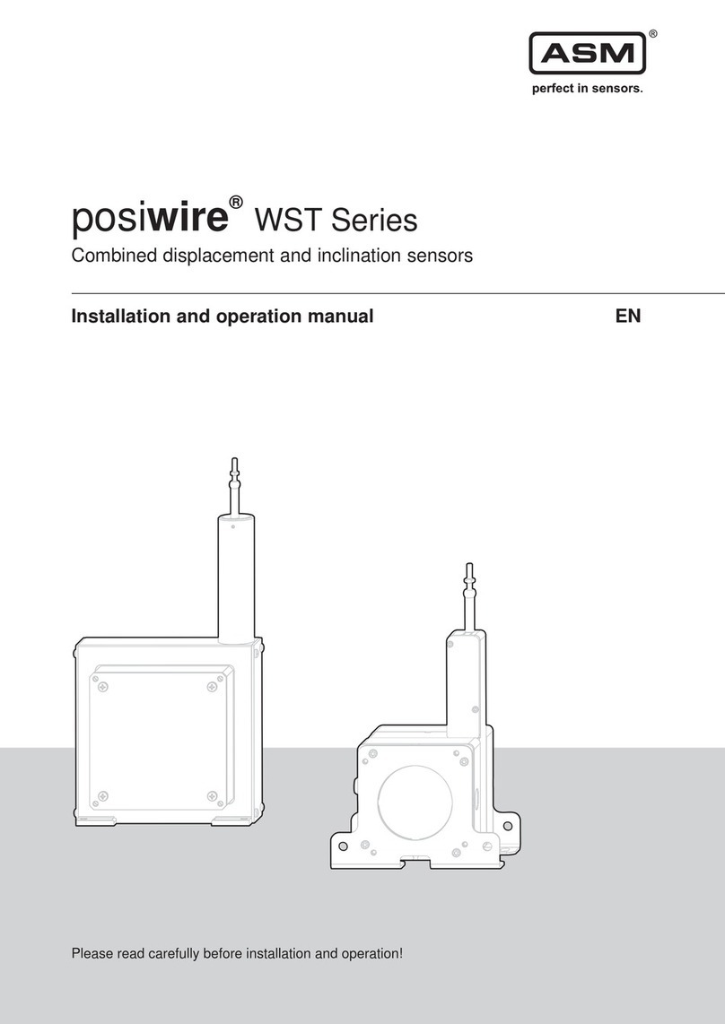
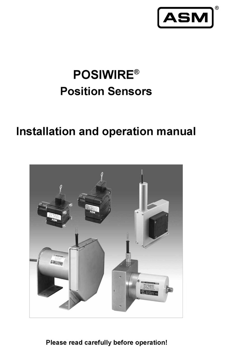
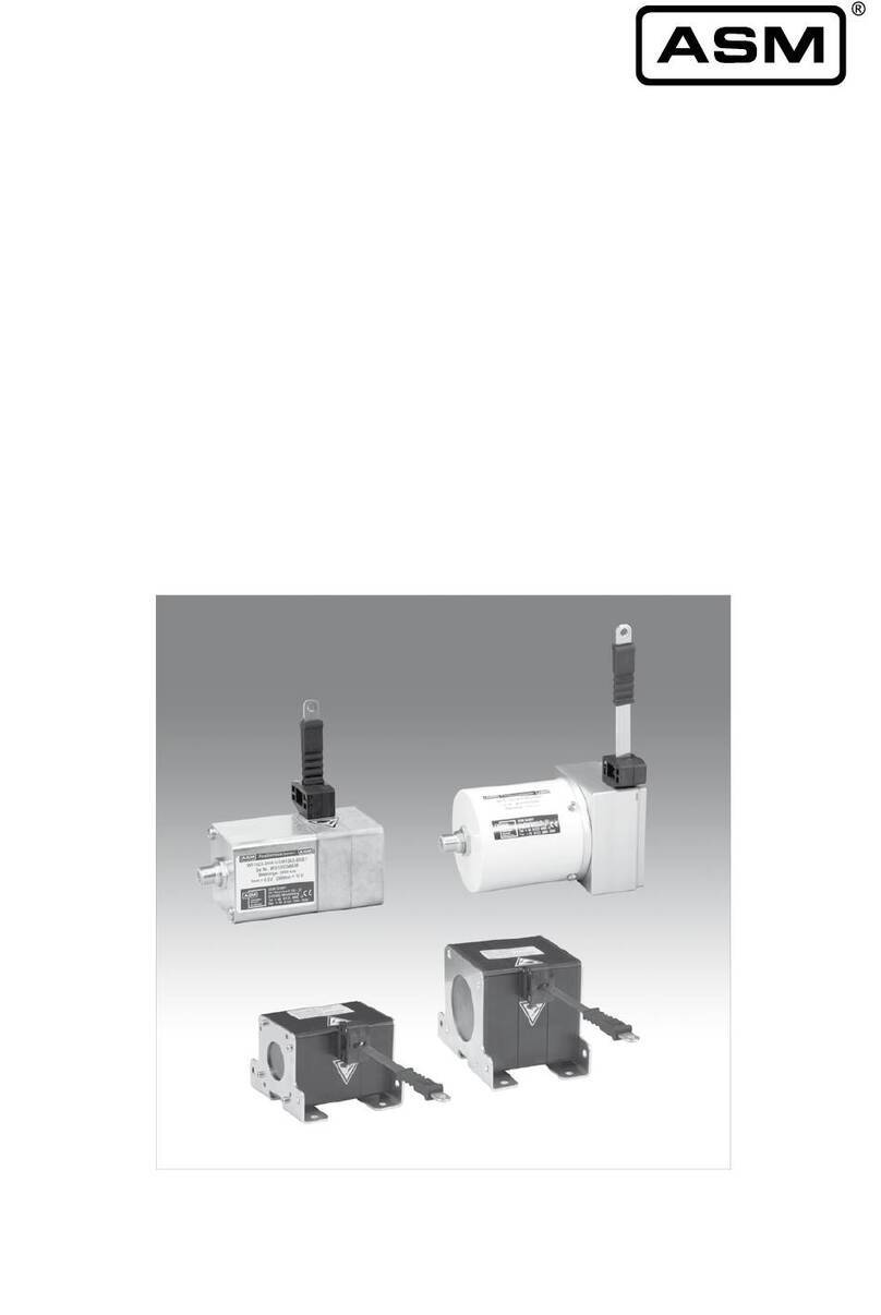
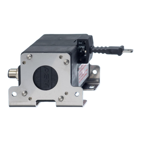
ASM posiwire WS10EX User manual

Installation and operation manual EN
Please read carefully before installation and operation!
posiwire®
WS10EX, WS12EX
Cable Extension Position Sensors, dust-ex proof

© ASM Automation Sensorik Messtechnik GmbH, 2019
All rights reserved.
Am Bleichbach 18 - 24
85452 Moosinning
Germany

posiwire®
Cable Extension Position Sensors, dust-ex proof
Version 6.2.0
www.asm-sensor.com
3
1Safety instructions ........................................................................................................4
1.1 Signal words and symbols ............................................................................................................. 4
1.2 General safety instructions ............................................................................................................. 5
1.3 Dust-ex proof marking .................................................................................................................... 6
1.4 Intended use................................................................................................................................... 7
2Transport and storage...................................................................................................8
3Installation and initial operation...................................................................................9
3.1 Mechanical installation ................................................................................................................... 9
3.2 Electrical connection .................................................................................................................... 14
3.3 Operating temperature ................................................................................................................. 16
4Maintenance and disposal..........................................................................................17
4.1 Maintenance and repair ............................................................................................................... 17
4.2 Deinstallation (dust-ex proof standard-compliant) ....................................................................... 18
4.3 Disposal ........................................................................................................................................ 18
5Output specification....................................................................................................19
5.1 Measurement signal and range.................................................................................................... 19
5.2 Analog output ............................................................................................................................... 20
5.3 Output information ........................................................................................................................ 24
6EU Declaration of Conformity.....................................................................................27
posiwire®
Cable Extension Position Sensors, dust-ex proof
4
Version 6.2.0
www.asm-sensor.com
Pos: 6 /Bedienungs anleitungen/Mo dule Universal/Ü berschriften/ Sicherheitshi nweise UE @ 6\mod_15076 30884828_78. docx @ 48429 @ 1 @ 1
1 Safety instructions
Pos: 7 /Sicher heitshinweise/Sign alwörter und S ymbole UE @ 1\ mod_140014 0467807_78.d ocx @ 9166 @ 2 @ 1
1.1 Signal words and symbols
Pos: 8 /Sicher heitshinweise/Sign alwörter @ 1 \mod_1400240 492762_78.doc x @ 9385 @ @ 1
WARNING, Risk of Injury:
Indicates a potentially hazardous situation, which, if not avoided, can result in serious
injury or property damage.
WARNING, Risk of Personal Injury or Death:
Indicates a situation that can result in serious personal injury or death if not properly
avoided.
WARNING, Risk of Personal Injury or Death:
Indicates a situation that can result in moderate personal injury or death if not properly
avoided.
WARNING, Risk of Personal Injury:
Indicates a situation that can result in minor personal injury if not properly avoided.
WARNING, Risk of Property Damage:
Indicates a situation that can result in minor to major property damage if not properly
avoided.
Product liability
• Disregarding the following instructions may result in malfunction, damage to property and personal injury
and releases the manufacturer from product liability.
Safety regulations
• National safety regulations must be observed!
Pos: 9 /###### ##### Seitenu mbruch ######## ########## ############ ##### @ 0\m od_13535841688 94_0.docx @ 336 @ @ 1

posiwire®
Cable Extension Position Sensors, dust-ex proof
Version 6.2.0
www.asm-sensor.com
5
Pos: 10 /Sicherh eitshinweise/Sich erheitshinweis e_EX @ 8\m od_15668916 09782_78.doc x @ 67520 @ 2 @ 1
1.2 General safety instructions
Danger of explosion! Danger of injury to persons or damage to the property
• Mounting or servicing of the sensor only by qualified personnel who must have
knowledge about the type of ex-protection, regulation and ordinance of operating
equipment in ex-proof areas.
Explosion risk due to use in non-conforming environment
• The sensor must only be used in the specified environment.
• Special notes concerning the electrical installation of dust-ex proof sensors must be
observed.
Pos: 11 /Sicherh eitshinweise/Sich erheitshinweis e_WS @ 8\ mod_1566891 570186_78.docx @ 67515 @ @ 1
Danger of injury to the operator or damage to the property
• Connection to power supply must be performed in accordance with safety
instructions for electrical facilities and performed only by qualified personnel.
• Any alteration, reconstruction or extension of the sensor is not allowed!
• The sensor must be operated only within values specified in the catalog or
datasheet.
• The danger of personal injury and danger of property damage due to a
malfunction of the sensor in machines or systems must be excluded by
additional safety measures.
• In safety-relevant applications, additional facilities must be provided for
maintaining safety and preventing damage.
• Check whether the protection class of the sensor is suitable for the application.
Risk of crushing and cutting injury due to pre-tensioned spring being released
from housing when opened!
• Do not open the sensor.
Risk of cutting injury due to uncontrolled retraction of the cable
• Do not damage the measuring cable!
• Do not let the measuring cable and the cable fixing spring back uncontrolled!
• Do not exceed the maximum cable extension range!
• Do not bend the measuring cable!
• Do not let the measuring cable be dragged on objects!

posiwire®
Cable Extension Position Sensors, dust-ex proof
6
Version 6.2.0
www.asm-sensor.com
Mechanical damage or destruction of the sensor
• Avoid impact and shock to the sensor.
• Do not allow the measuring cable to spring back uncontrolled.
• Do not pull out the measuring cable beyond the range of the sensor.
Malfunction due to the accumulation of dirt on the measuring cable
• Do not oil or lubricate the measuring cable.
Pos: 12 /Bedienung sanleitunge n/Posiwire/Ken nzeichnung der WS-EX-Sensoren @ 5\mod_1499173 361214_78.d ocx @ 44202 @ 2 @ 1
1.3 Dust-ex proof marking
The Dust-ex proof marking according to the guideline 2014/34/EU is lasered on the sensor housing.
These are:
WS10EX:
II 3D
Ex tc IIIC T80°C Dc X
WS12EX
II 3D
Ex tc IIIC T80°C Dc
This means:
II
=
Equipment-group II: Equipment not intended for use in underground parts of mines, as
well as their overground plants, which are endangered by firedamp or/and combustible
dusts
3
=
Equipment category 3: Normal level of safety – application in dust explosion hazardous
areas. Equipment in this category is intended for use in areas in which explosive
atmospheres – in the case of this sensor caused by dispersed dust – are unlikely to
occur, or, if they do occur, are likely to do so only infrequently and for a short period
only. Equipment in this category ensures the requisite level of protection during normal
operation.
D
=
Air/dust mixture
EX
=
This symbol indicates that the electrical equipment complies with one or more types of
protection
tc
=
Ignition protection class: protection by enclosure IP65
IIIC
=
Group for conductive dust
T80°C
=
Maximum surface temperature of the Cable Extension Position Sensor
Dc
=
Equipment Protection Level (EPL): EPL „Dc“ complies with the categorie 3D
X
=
Resists an impact with reduced impact energy of 4J, without X the sensor resists an
impact of 7J impact energy
Pos: 13 /##### ###### Seitenum bruch ####### ########### ############# #### @ 0\ mod_1353584168 894_0.docx @ 336 @ @ 1

posiwire®
Cable Extension Position Sensors, dust-ex proof
Version 6.2.0
www.asm-sensor.com
7
Pos: 14 /Sicherh eitshinweise/Bes timmungsge mäße Verwendung/ Bestimmungsg emäße Ver wendung UE @ 1\ mod_14001 42179648_78.d ocx @ 9192 @ 2 @ 1
1.4 Intended use
Pos: 15 /Bedienung sanleitungen/ Posiwire/Besti mmungsgemäße Verwendu ng WS_EX @ 5\mod_1499172 833281_78.doc x @ 44192 @ @ 1
posiwire® Cable Extension Position Sensors are intended for linear position measurement of linear guided
objects. For determining measuring range, environmental compatibility and connection data of the sensor,
please note the data sheet. Use the sensor as intended by operating within its specified technical data and
ambient conditions. The environmental conditions are specified in the dust-ex proof category of the sensor.
The installation and operating instructions supplied with the unit must be observed and all maintenance and
service work must be carried out. The data sheet of the respective sensor is part of this instruction manual. If
not yet available, it may be requested by stating the respective model number.
The sensor must not be used in applications with an explosive gas atmosphere or higher explosive dust
atmosphere that requires a higher rated device.
Do not use the sensor in the following environmental conditions:
• abrasive dust e.g. dust including metal or metaloxid, stone dust, glass dust, ceramic dust
• corrosive and aggressive media e.g. atmospheres containing chloride.
Pos: 16 /##### ###### Seitenum bruch ####### ########### ############# #### @ 0\ mod_1353584168 894_0.docx @ 336 @ @ 1

posiwire®
Cable Extension Position Sensors, dust-ex proof
8
Version 6.2.0
www.asm-sensor.com
Pos: 17 /Bedienung sanleitungen/ Posiwire/Transp ort und Lageru ng_WS_EX @ 7\mod_1 524139823528_ 78.docx @ 5514 5 @ 1 @ 1
2 Transport and storage
Loss of explosion protection in case of shipment damages
• Check sensor immediately for shipment damage.
• Damaged sensors may no longer meet the specified EX rating and must not be
mounted and operated in explosion-risk areas.
Risk of damage to the measuring cable or cable fixing
• Do not lift the sensor by the cable or cable attachment.
Observe storage and transport temperatures according to the operating temperature (see data sheet).
Max. rel. humidity 60%, condensation must be excluded.
The device must be secured against slipping and tipping during transport.
Unpacking
Do not unpack sensor by pulling cable or cable clip.
Shipment damages
Check sensor immediately for shipment damage. In case of any damage, please contact your supplier.
Pos: 18 /Bedienung sanleitungen/ Posiwire/Liefer umfang_EX @ 7 \mod_1533 119760097_7 8.docx @ 5792 1 @ @ 1
Removing kink protection
The kink protection prevents the cable fixing from buckling and damaging the cable. Remove in the direction
of the cable.
Shipment content
• Sensor
• Installation and operation manual
Pos: 19 /##### ###### Seitenum bruch ####### ########### ############# #### @ 0\ mod_1353584168 894_0.docx @ 336 @ @ 1

posiwire®
Cable Extension Position Sensors, dust-ex proof
Version 6.2.0
www.asm-sensor.com
9
Pos: 20 /Bedienung sanleitungen/M odule Uni versal/Überschrifte n/Montage, In betriebnahme U E @ 4\mod _1491474694 256_78.docx @ 38 324 @ 1 @ 1
3 Installation and initial operation
Pos: 21 /Bedienung sanleitungen/ Posiwire/Montag e_man @ 3\ mod_145804 1468522_78.doc x @ 23241 @ 2 @ 1
3.1 Mechanical installation
Risk of injury from touching the moving measuring cable or moving parts
during operation
• Operate the sensor only with a suitable protective device (e.g. cable cover) to
prevent injury!
Choice of installation position
• Select a protected installation position for the measuring cable.
This prevents damage of the measuring cable.
• Preferably mount the sensor with the cable outlet pointing downwards.
This prevents liquids from entering through the cable outlet.
• Screw the sensor onto a flat surface or provide a three-point mounting.
This avoids distortion and damage to the sensor.
• In harsh environments provide protection for the measuring cable.

posiwire®
Cable Extension Position Sensors, dust-ex proof
10
Version 6.2.0
www.asm-sensor.com
Cable travel should only be axial to the cable outlet - no misalignment is
allowed
• Cable misalignment shortens service life of sensor and causes error in
measurement. Warranty will not be granted for damage caused by misalignment.
correct incorrect
Sensor with
horizontal extension
Sensor with vertical
extension
• If the measuring cable cannot be extended in the axial direction of the cable
outlet opening due to the measuring task, the SR2 cable pulley must be used to
redirect the cable.
• For special applications, extension cables with cable clips attached on both ends
are available.
Fixing the sensor
Depending upon the sensor model, holes in the base plate, threads, mounting brackets or T-slots in the
sensor housing enable attachment of the sensor. Required dimensions are listed in the data sheet.
Mount the sensor on flat surface.
Use flat washers and/or thread locker if necessary.
The torques of the fixing screws depend on the material used (see p.13).

posiwire®
Cable Extension Position Sensors, dust-ex proof
Version 6.2.0
www.asm-sensor.com
11
Cable attachment device
The cable clip can be fastened as follows:
• M4 cable connection in cable outlet direction
The M4 connection is mounted with a
through hole, two washers and a M4
nut.
Do not rotate the M4 connection
during assembly, otherwise the
measuring cable will be twisted!
• Cable clip with Allen screw M5: standard fixing.
• Cable clip with attachment head (accessory GK1: metal, GK2: plastic): fast cable attachment, easy to
remove
• Cable clip with magnetic clamp (accessory MAG1): with this device the sensor can be easily used at
several measuring points with ferromagnetic surface.

posiwire®
Cable Extension Position Sensors, dust-ex proof
12
Version 6.2.0
www.asm-sensor.com
Cable clip attachment
The cable clip (see drawing above) can be opened for easy attachment of the measuring cable. If possible,
fasten cable fixing with cable in retracted position.
Mounting aid for adverse installation conditions
For example, fit a mounting loop and put it around your wrist. Do not remove the mounting loop until after
final installation.
Pos: 22 /##### ###### Seitenum bruch #### ############## ########### ###### @ 0\ mod_1353584168 894_0.docx @ 336 @ @ 1
Danger of cutting injuries due to cable clips during cable connection
• Before connecting the cable clip into the fixture read the mounting instructions.

posiwire®
Cable Extension Position Sensors, dust-ex proof
Version 6.2.0
www.asm-sensor.com
13
Pos: 23 /Bedienung sanleitungen/ Posiwire/Anzugs momente WS 10EX @ 7\ mod_153311749 6267_78.doc x @ 57905 @ @ 1
Fixing screws
WS10EX
Model
Screw
Screw
material
Torque
[Nm]
WS10EX
M5, 8 mm deep
A2
2,0
Pos: 24 /Bedienung sanleitungen/ Posiwire/Anzugs momente WS 12EX @ 7\ mod_153311771 4489_78.doc x @ 57910 @ @ 1
WS12EX
Model
Screw
Screw
material
Torque
[Nm]
WS12EX
M5, 10 mm deep
A2
2.0
Pos: 25 /Bedienung sanleitungen/ Posiwire/Montag e_EX_mecha nisch @ 6\m od_152024345 8267_78.docx @ 53005 @ @ 1
d
Special notes concerning the mounting of posiwire®dust-ex proof sensors
Explosion risk due to incorrect installation
• Installation must only be taken in non-explosive conditions!
• Dust deposits are to be avoided!
• Do not mount the sensor in the dust particle stream!
• Protect the sensor against damage!
The housings have been examined with the impact energy DIN EN 60079-1:
• WS10EX at 4 Joule
• WS12EX at 7 Joule
Ambient temperature: -20°C to 40°C
Maximum cable velocity: vmax = 2m/s
Pos: 26 /##### ###### Seitenum bruch ####### ########### ########### ###### @ 0\ mod_1353584168 894_0.docx @ 336 @ @ 1

posiwire®
Cable Extension Position Sensors, dust-ex proof
14
Version 6.2.0
www.asm-sensor.com
Pos: 27 /Bedienung sanleitungen/ Posiwire/Elektri scher Anschl uss_EX @ 7\ mod_1531464 372555_78.doc x @ 57685 @ 2 @ 1
3.2 Electrical connection
Explosion risk!
• Mounting / removal of the sensor must only be undertaken in non-explosive
conditions.
Damage or destruction of the sensor due to excessive operating voltage or
mounting error
• The applied operating voltage must not exceed the value specified in the data sheet.
• Operate the sensor only within the limits specified in the data sheet.
• Connect to the power supply only by qualified personnel and in accordance with the
applicable safety regulations for electrical equipment.
• Do not connect or disconnect the sensor under tension!
Corrosion in the sensor due to moisture penetration
• Use the sensor only according to protection class.
• Avoid crossing the dew point.
• Cable outputs must be installed in such a way that no moisture can get into the
cable.
Damage of the sensor cable due to mechanical stress
• Do not strain the connection cable.
• A separate strain relief is recommended.
Connector Pin assignment
Must be in accordance with the output types contained in the appendix.
Supply voltage
See specification in the data sheet of the sensor. The maximum operating voltage must not be exceeded.
Connection example: current output 420A
To convert the 4 ... 20 mA signal into a voltage signal, it needs a load resistor RM (measuring resistor) as
shown in the diagram. The maximum value of RM depends on the cable resistance RL and the excitation
voltage UB:
RMmax = ((UB –12 V)/0,02 A) –RL
With an excitation of 24 V DC and a cable resistance RL = 500 Ω a maximum value of RM = 100 Ω can be
used (see from page 19) .
Pos: 28 /##### ###### Seitenum bruch ####### ########### ############# #### @ 0\ mod_1353584168 894_0.docx @ 336 @ @ 1

posiwire®
Cable Extension Position Sensors, dust-ex proof
Version 6.2.0
www.asm-sensor.com
15
Pos: 29 /Bedienung sanleitungen/ Posiwire/Montag e_EX_elektri sch @ 7\mod _15210256147 97_78.docx @ 53570 @ @ 1
Special notes concerning the electrical installation of Dust-EX-proof sensors
• Installation according to DIN EN 60079-14.
• Cable must be properly secured and protected against damage.
• Cable must be protected from UV-radiation!
• The sensor, the wire shield and the wire must be connected to the local
equalization system.
• The connection cross-section of the sensor must be at least 4 mm2.
Pos: 30 /Bedienung sanleitungen/M odule Uni versal/Montage Se nsorkabel @ 6\mod_151 9651235286_78.d ocx @ 52835 @ @ 1
Installation of the sensor supply cable
incorrect
correct
Admissible bending radius of the
cable must be observed:
R ~ 5 x D
R ~ 10 x D (underwater cable)
Length compensation for the
cable must be observed
A separate cord grip for cable
strain relief is recommended
Observe cable routing in case of
splashing water, water
condensation and humidity
Pos: 31 /##### ###### Seitenum bruch ####### ########### ############# #### @ 0\ mod_1353584168 894_0.docx @ 336 @ @ 1

posiwire®
Cable Extension Position Sensors, dust-ex proof
16
Version 6.2.0
www.asm-sensor.com
Pos: 32 /Bedienung sanleitungen/ Posiwire/WS_ EX_EMV @ 7\mod_15314 64645363_78.d ocx @ 57691 @ @ 1
Electromagnetic Compatibility (EMC)
Electromagnetic compatibility of posiwire® Cable Extension Position Sensors dust-ex proof is influenced by
the sensor wiring.
Pos: 33 /Bedienung sanleitungen/ Posiwire/Arbeitst emperatur_Ü bersicht_WS_EX @ 7\mod _15359620922 37_78.docx @ 58495 @ 2 @ 1
3.3 Operating temperature
posiwire® WS10EX
-20 … +40°C
posiwire® WS12EX
-20 … +40°C
Pos: 34 /##### ###### Seitenum bruch ####### ########### ############# #### @ 0\ mod_1353584168 894_0.docx @ 336 @ @ 1
Possible malfunction of the sensor when used in systems with highly
interference-prone components such as frequency inverters
Recommended wiring:
• Use single shielded sensor cable with twisted pair conductors for power supply
and signal output.
• Connect the cable shield to ground on one side of the control cabinet. Connect
the shield connection over a large area using cable clamps before or at the cable
entry into the control cabinet. When preassembled cables are delivered, the
screen is not connected to the housing on the sensor side.
• Do not install sensor cables close to power conductors such as motor or
contactor control cables (use separate cable ducts for signal and power cables).
• Install the cables in metal cable ducts which are connected to the same earth
bonding as the dust-ex proof sensors.

posiwire®
Cable Extension Position Sensors, dust-ex proof
Version 6.2.0
www.asm-sensor.com
17
Pos: 35 /Bedienung sanleitungen/M odule Uni versal/Überschrifte n/Instandhaltung und Entsorgung UE @ 6\ mod_1507630 731526_78.docx @ 48417 @ 1 @ 1
4 Maintenance and disposal
Pos: 36 /Bedienung sanleitungen/ Posiwire/Insta ndhaltung_Wart ung_WS-EX @ 5\mod_14 99240685099_7 8.docx @ 44244 @ 2 @ 1
4.1 Maintenance and repair
Explosion risk!
• Maintenance may only be undertaken in non-explosive atmospheric conditions.
Risk of crushing and cutting injury due to pre-tensioned spring being released
from housing when opened!
• Do not open the sensor.
• Due to possible risk of injury by improper handling, we strongly advise against
repair attempts.
Maintenance interval
• Within maintenance activities, especially those parts of the sensor which are associated with the risk of
ignition must be checked (e.g. the integrity of connectors, cables, seals etc.). Maintenance intervals are
application specific and must be determined by the customer depending on the operating conditions.
• Dust concentrations are not allowed – remove any dust deposit – appropriate maintenance intervals
must be scheduled.
Check sensor regularly for possible damage:
Inspection of …
Measures
Check for dust deposit
Remove dust
Integrity of housing
Send damaged sensor to ASM for repair
Integrity of connector, cable
Replace damaged parts resp. send sensor to ASM for repair
Mounting elements
Tighten mounting parts with recommended torque, if applicable use bolt
adhesive
Cable
Damaged cable, spliced or bended cable: send sensor to ASM for
repair
Opening the sensor by the customer will void the protection type:
• Do not open the sensor.
Pos: 37 /Bedienung sanleitungen/ Posiwire/WS_ Kalibrierung @ 4 \mod_1491 566471251_7 8.docx @ 38399 @ @ 1
Calibration
The recommended calibration interval is 1 year.
Test protocol and traceable calibration certificate (ISO9001 / ISO10012) is available on request.
Pos: 38 /Steuerm odule/###### ##### Seitenu mbruch ####### ############## ########### ### @ 1\ mod_14011100 37783_0.docx @ 9678 @ @ 1

posiwire®
Cable Extension Position Sensors, dust-ex proof
18
Version 6.2.0
www.asm-sensor.com
Pos: 39 /Bedienung sanleitungen/ Posiwire/WS_ EX_Demontage @ 6\mod_ 15198161447 24_78.docx @ 529 12 @ 2 @ 1
4.2 Deinstallation (dust-ex proof standard-compliant)
Danger of explosion due to incorrect deinstallation
• Remove sensor only in de-energized condition.
• Removal of the sensor must only be undertaken in non-explosive conditions.
Pos: 40 /Bedienung sanleitungen/ Posiwire/WS_ Entsorgung @ 6\mod_1507 649730932_78. docx @ 48485 @ 2 @ 1
4.3 Disposal
Disposal according to applicable government regulations.
Pos: 41 /Steuerm odule/###### ##### Seitenu mbruch ####### ############## ########### ### @ 1\ mod_14011100 37783_0.docx @ 9678 @ @ 1

posiwire®
Cable Extension Position Sensors, dust-ex proof
Version 6.2.0
www.asm-sensor.com
19
Pos: 42 /Ausg angsarten/Spezifikati on Ausgang U E @ 1\ mod_1397662705 340_78.docx @ 8 534 @ 1 @ 1
5 Output specification
Pos: 43 /Bedienung sanleitungen/ Posiwire/Messsig nal und Mess bereich WS E X @ 7\mod _152103174900 2_78.docx @ 53 835 @ 2 @ 1
5.1 Measurement signal and range
Analog, not calibrated
Output: voltage divider, sensitivity not adjustable
Resistance range is used from about 3% to 97%. 0% or 100% is not possible.
Individual sensitivity is specified on the label.
Position
0%
30%
100%
Measurement value
approx. 3%
approx. 30%
approx. 97%
Analog, calibrated
Integrated signal conditioner, sensitivity adjusted
Measuring range corresponds to the electrical measuring range (e.g. 4...20 mA).
Position
0%
30%
100%
Measurement value
4 mA
8.8 mA
20 mA
Pos: 44 /Steuerm odule/###### ##### Seitenu mbruch ##### ########### ############# ###### @ 1\ mod_14011100 37783_0.docx @ 9678 @ @ 1

posiwire®
Cable Extension Position Sensors, dust-ex proof
20
Version 6.2.0
www.asm-sensor.com
Pos: 45 /Bedienung sanleitungen/M odule Uni versal/Überschrifte n/Analog-A usgänge UE @ 7\mod_15337 27051463_78.d ocx @ 58015 @ 2 @ 1
5.2 Analog output
Pos: 46 /Ausg angsarten/Posi wire/Analog-Ausgä nge/R1K/Spa nnungsteiler R1 K_für EX @ 6 \mod_1520418 741096_78.doc x @ 53025 @ @ 1
Voltage divider
R1K
Potentiometer
Excitation voltage
24 V DC (32 V DC max. at 1 kΩ, max. power
1 W)
Potentiometer impedance
1 kΩ ±10 %
Thermal coefficient
±25 x 10-6 / °C f.s.
Sensitivity
Depends on the measuring range, individual
sensitivity of the sensor is specified on the
label
Voltage divider utilization range
approx. 3 % … approx. 97 %
Operating temperature
Refer to output specification
EMC
DIN EN 61326-1:2013
The metal wiper of the potentiometer must be protected against current load
• Electrical current flow impact on the wiper causes linearity errors and shortens
the lifetime of the potentiometer.
Additional information:
https://www.asm-sensor.com/en/downloads.html?file=files/asmTheme/pdf/
ws_poti_technote_en.pdf
Signal wiring
Output signals
Cable color
Poti +
white
Poti GND
brown
Poti slider
green
Not connected
yellow
Not connected
grey
Not connected
pink
Not connected
blue
Not connected
red
Pos: 47 /Steuerm odule/###### ##### Seitenu mbruch ##### ########### ############# ###### @ 1\ mod_14011100 37783_0.docx @ 9678 @ @ 1
This manual suits for next models
1
Table of contents
Other ASM Accessories manuals

ASM
ASM posirot PRAS Series User manual

ASM
ASM posirot PRAS Series User manual

ASM
ASM Posihall PH36 Owner's manual

ASM
ASM POSIROT PRAS User manual

ASM
ASM posirot PRAS2EX User manual

ASM
ASM posiwire User manual

ASM
ASM PRDS-CANOPR User manual

ASM
ASM POSITAPE WB Series User manual

ASM
ASM positape WBT Series User manual

ASM
ASM posirot PRAS Series User manual
Popular Accessories manuals by other brands

Yamaha
Yamaha FC7 owner's manual

Sartorius
Sartorius WZA224-LC installation instructions

DOL
DOL 58 Technical user guide

Eaton
Eaton Crouse-Hinds IF 1744 Installation & maintenance information

Hornbach
Hornbach 6145050 Installation and user manual

Acuity Brands
Acuity Brands sensorswitch SFR Series Programming instructions