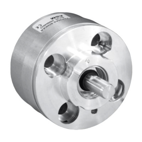
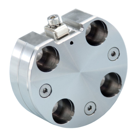
ASM posirot PRAS Series User manual

POSIROT®/ PRAS
Analog Magnetic
Angle Sensors
Instruction Manual
Please read carefully before installation and operation!

2 MAN-PRAS-E-12 ASM GmbH
www.asm-sensor.com
POSIROT®
Contents
Contents Safety instructions 3
Description 4
Mounting 4
Placement and alignment of the position magnet 4
Reference position 6
Torque for the mounting screws 7
Electrical installation 7
Sensor fixing with shield 8
Outline drawings 9
Specification of the outputs 21
Accessories 22
Accessory cables 22
Position magnets 23
Mounting plates 27
Reliability characteristics 29
Declaration of conformity 30

ASM GmbH MAN-PRAS-E-12 3
www.asm-sensor.com
POSIROT®
Instruction Manual
Do not use POSIROT®position sensors in safety critical appli-
cations where malfunction or total failure of the sensor may
cause danger for man or machine.
For safety related applications additional mechanisms (de-
vices) are necessary to maintain safety and to avoid damage.
Disregard of this advice releases the manufacturer from pro-
duct liability.
The sensor must be operated only within values specied in
the catalog or datasheet.
Connection to power supply must be performed in accordance
with safety instructions for electrical facilities and performed
only by trained staff.
Safety
instructions

4 MAN-PRAS-E-12 ASM GmbH
www.asm-sensor.com
POSIROT®
Instruction Manual
Description The angle sensors PRAS of the POSIROT®product family perform touch-
less or shaft based angle measurement. A position magnet rotates in front
of the sensing area of the sensor head. The angular position is converted
into a standardized high resolution voltage or current output. Measuring
ranges 15° to 360° having rising or falling characteristic are available.
Placement and alignment of the position magnet
Mounting
For non-contact sensor models air gap and alignment of sensor and
position magnet has to be observed. The linearity will degrade in case of
misalignment.
Adjacent magnetic elds or ferromagnetic materials can inuence the
measurement results of the PRAS sensors of the POSIROT®product
family. Therefore the angle sensors should be mounted solely with
nonmagnetic / non magnetisable shields and screws.
The angle sensors PRAS2, PRAS3 and PRAS5 are equipped with
an integrated magnetic shield which minimizes the sensitivity against
external magnetic elds.
OptionalshieldplatesareavailablefortheanglesensorsPRAS20,PRAS21
and PRAS27. They can reduce the effect of residual magnetizing in case
the sensor has to be mounted on a ferromagnetic material (see page 8).
It is however not possible to exclude the effect of lateral external magnetic
elds.

a
c
b
a
c
b
ASM GmbH MAN-PRAS-E-12 5
www.asm-sensor.com
POSIROT®
Instruction Manual
Mounting
(continued)
Measuring error by misalignment of the position magnet
Sensor Position
magnet
Air gap
[mm]
Paral-
lelism
[°]
Error by axial misalignment
[°]
0,2
mm
0,5
mm 1 mm 2 mm 3 mm 4 mm
PRAS1 PRMAG20 0 ... 6,5 0 ... 5 0,15 0,4 0,8 2,2 5,0 –
PRMAG21 0 ... 4 0 ... 5 0,2 0,4 1,0 3,8 10 –
PRMAG22 0 ... 9,5 0 ... 5 0,1 0,4 1,0 2,2 4,5 8,0
PRAS2 PRMAG20 0 ... 6 0 ... 5 0,15 0,4 0,8 2,2 5,0 –
PRMAG21 0 ... 3,5 0 ... 5 0,2 0,4 1,0 3,8 10 –
PRMAG22 0 ... 9,0 0 ... 5 0,1 0,4 1,0 2,2 4,5 8,0
PRAS5 PRMAG5-Z 0 ... 7,5 0 ... 5 0,1 0,2 0,6 1,5 4,5 8,5
PRMAG20 0 ... 5,5 0 ... 5 0,15 0,4 0,8 2,2 5,0 –
PRMAG21 0 ... 3 0 ... 5 0,2 0,4 1,0 3,8 10 –
PRMAG22 0 ... 8,5 0 ... 5 0,1 0,4 1,0 2,2 4,5 8,0
PRAS20 PRMAG20 0 ... 7 0 ... 5 0,1 0,3 0,7 2,0 4,6 –
PRMAG21 0 ... 2 0 ... 5 0,15 0,3 0,9 3,6 9,6 –
PRMAG22 0 ... 10 0 ... 5 0,0 0,0 0,7 1,5 3,8 7,0
PRAS21 PRMAG20 0 ... 7,0 0 ... 5 0,1 0,3 0,7 2,0 4,6 –
PRMAG21 0 ... 2 0 ... 5 0,15 0,3 0,9 3,6 9,6 –
PRMAG22 0 ... 10 0 ... 5 0,0 0,0 0,7 1,5 3,8 7,0
PRAS27 PRMAG20 0 ... 7,5 0 ... 5 0,1 0,3 0,7 2,0 4,6 –
PRMAG21 0 ... 2,5 0 ... 5 0,15 0,3 0,9 3,6 9,6 –
PRMAG22 0 ... 10,5 0 ... 5 0,0 0,0 0,7 1,5 3,8 7,0

6 MAN-PRAS-E-12 ASM GmbH
www.asm-sensor.com
Mounting
(continued)
Reference position
For ease of mounting there are reference markings at housing, position
magnet and near the shaft. If both markings match output will be on the
50% of full scale.
Clockwise increasing signal (CW), view to sensor measuring area/shaft
Counterclockwise increasing signal (CCW), view to sensor measuring area/shaft
Example for angle range 90°
Example for angle range 360°
POSIROT®
Instruction Manual
Range [°]
Marking
Range [°]
Marking
Marking
Marking

ASM GmbH MAN-PRAS-E-12 7
www.asm-sensor.com
POSIROT®/
Instruction Manual
Mounting
(continued)
Torque for xing screws
Electrical installation
Supply voltage, current consumption, wiring
For wiring of connector or cable outlet as well as supply voltage and current
consumption refer to chapter „Specication of the outputs“ at the end of this
manual.
Cable screen has to be connected to protective earth.
Caution: Observe different color code for pre-assembled accessory cables
- refer to accessories pages.
The protection class of sensors with connector output is valid only if the
electrical plug is connected!
Caution: Do not twist the M12 connector insert.
Cable outputs must be installed in such a way that no moisture can get into
the cable.
Crossing the dew point must be avoided.
A separate cord grip is recommended.
Output Value range 50% value of output signal
U2 0.5 ... 10 V 5.25 V
U6 0.5 ... 4.5 V 2.5 V
I1 4 ... 20 mA 12 mA
Torque Mounting method Material Torque
[Nm]
Nuts M12x1 (PRAS1) – 2.5
M2,5 screws for mounting brackets (PRAS2,
PRAS3) – 0.8
M3 screws for mounting ange (PRAS3) – 1.2
M3 screws with washer (PRAS21) A4
Aluminium
Brass
Plastic
<0.8
–
–
–
M4 screws with washer (PRAS20) A4
Aluminium
Brass
Plastic
<1.8
–
–
–
M4 screws (PRAS24, PRAS27) – 1

8 MAN-PRAS-E-12 ASM GmbH
www.asm-sensor.com
POSIROT®
Instruction Manual
Mounting
(continued)
PRAS20
shield plate
PRAS21
shield plate
PRAS27
shield plate
Sensor xing with a shield plate (optional)
PRAS20
PRAS21
PRAS27

ASM GmbH MAN-PRAS-E-12 9
www.asm-sensor.com
POSIROT®
Instruction Manual
Outline drawing
PRAS1
Connector version
Outline drawing
PRAS1
Cable version
Weight without cable 20 g approx.
Dimensions informative only.
For guaranteed dimensions consult factory.
Dimensions in mm [inch]
Position
magnet
Marking
Dimensions in mm [inch]
Marking
Position
magnet
Measuring area
Marking
M12 connector
Measuring area

bündig
nicht magnetisches Material
nicht bündig
magnetisches Material
15
>
Mar
kierung
Markieru
ng
10 MAN-PRAS-E-12 ASM GmbH
www.asm-sensor.com
POSIROT®
Instruction Manual
Marking
Marking
Reference
position
Mounting PRAS1
Flush-mounted
Non-magnetic material
In case of
magnetic material

Ma
rkierung
Markier
ung
ASM GmbH MAN-PRAS-E-12 11
www.asm-sensor.com
Outline drawing
PRAS2
Cable version
Weight without cable 40 g approx.
Dimensions informative only.
For guaranteed dimensions consult factory.
Dimensions in mm [inch]
Marking
Position
magnet Measuring area
POSIROT®
Instruction Manual
Marking
Marking

Positions-
magnet
33 [1.299]
3[0.118]
2,5 [0.098]
2,5[0.098]
20[0.787]
36[1.417]
42[1.654]
Markierung
M12 Stecker
Messfläche
Befestigungexzenter
PRPT-BFS1
Markierung
Markierung
12 MAN-PRAS-E-12 ASM GmbH
www.asm-sensor.com
POSIROT®
Instruction Manual
Outline drawing
PRAS2
Connector version
M12 axial
Weight without cable 50 g approx.
Dimensions informative only.
For guaranteed dimensions consult factory.
Dimensions in mm [inch]
Connector M12
Marking
Position
magnet Measuring area
Reference
position
Marking
Marking
Also for connector version
Mounting clamps
PRPT-BFS1

Markierung
Markierung
ASM GmbH MAN-PRAS-E-12 13
www.asm-sensor.com
POSIROT®
Instruction Manual
Outline drawing
PRAS2
Connector version
M12 radial
Weight without cable 50 g approx.
Dimensions informative only.
For guaranteed dimensions consult factory.
Marking
Position
magnet
Connector M12
Measuring area
Dimensions in mm [inch]
Reference
position
Marking
Marking

14 MAN-PRAS-E-12 ASM GmbH
www.asm-sensor.com
POSIROT®
Instruction Manual
Outline drawing
PRAS3
Shaft
Weight without cable 250 g approx.
Dimensions informative only.
For guaranteed dimensions consult factory.
Marking
Dimensions in mm [inch]
Connector M12
Connector
M12
Flat area
Marking
Marking
(back side)
Reference
position Marking
(back side)

33 [1.299]
33 [1.299]Ø
7[.276]
3[.118]
47[1.850]
2,5[.098]
2,5[.098]
6
-0
0,01
+
.236
-0
.0005
+
[]
26
0,05
1.024
.002
[]
4 x M3-5 [.197]
Markierung
63[2.480]7[.276]
7[.276]
52[2.047]
Markierung
36 [1.417]Ø
ASM GmbH MAN-PRAS-E-12 15
www.asm-sensor.com
Flat area
Marking
Marking
(back side)
POSIROT®
Instruction Manual
Reference
position
Outline drawing
PRAS3
Hollow shaft
Dimensions in mm [inch]
Marking
Connector
M12
Connector M12
Weight without cable 250 g approx.
Dimensions informative only.
For guaranteed dimensions consult factory.
Marking
Marking
(back side)

34[1.339]
20[.787]
Meßfläche
M12-Stecker
15 [.591]
9 [.354]Ø
10[.394]
Positionsmagnet
66
-0,1
0
+2.598-.004
0
+
[]
48
0,05
1.890
.002
[]
Markierung
Markierung
Markierung
Markierung
Markierung
16 MAN-PRAS-E-12 ASM GmbH
www.asm-sensor.com
POSIROT®
Instruction Manual
Outline drawing
PRAS5
Connector M12
axial
Connector M12
Measuring area
Marking
Position magnet
Dimensions informative only.
For guaranteed dimensions consult factory.
Reference
position
Marking
Marking
Marking
Marking
Dimensions in mm [inch]

20[.787]
48
0,05
1.890
.002
[]
66
-0,1
0
+
2.598
-.004
0
+
[]
9 [.354]Ø
15 [.591]Ø
10[.394]
13 [.512]
M12-Stecker
Positionsmagnet
Meßfläche
Markierung
10[.394]
Markierung
Markierung
Markierung
Markierung
ASM GmbH MAN-PRAS-E-12 17
www.asm-sensor.com
POSIROT®
Instruction Manual
Reference
position
Marking
Marking
Marking
Marking
Outline drawing
PRAS5
Connector M12
radial
Connector M12
Measuring area
Marking
Position magnet
Dimensions informative only.
For guaranteed dimensions consult factory.
Dimensions in mm [inch]

Positions-
magnet
38 [1.496]Ø
48 [1.890]Ø
28[1.102]
20[.787]
30°
4,5[.177]
1,6 [.063]
6[.236]
Messfläche
Markierung
8 [.315]
17,5[.689]
18 MAN-PRAS-E-12 ASM GmbH
www.asm-sensor.com
POSIROT®
Instruction Manual
Outline drawing
PRAS20
Reference
position
Marking
Marking
Marking
Measuring area
Position
magnet
Dimensions in mm [inch]
Dimensions informative only.
For guaranteed dimensions
consult factory.
Marking
Marking

ASM GmbH MAN-PRAS-E-12 19
www.asm-sensor.com
Marking
Marking
Marking
Marking
Outline drawing
PRAS21
Reference
position
Dimensions in mm [inch]
Dimensions informative only.
For guaranteed dimensions
consult factory.
Marking
Measuring area
Position
magnet
POSIROT®
Instruction Manual

45,5 [1.791]
49,50,1 1.949 .004
[ ]
38 [1.496]
22 [.866]
10 [.394]
5 [.197]
18,2 [.717]
Meßfläche /
measurement area
Positionsmagnet /
position magnet
30[1.181]
R6,3[.248]
60°
5,2 [.205]
5[.197]
Ø
7,8 [.307]
Ø
Positionsmagnet /
position magnet
Kabel /
cable
Markierung /
marking
Markierung
Markierung
Markierung
Markierung
Zugentlastung
20 MAN-PRAS-E-12 ASM GmbH
www.asm-sensor.com
POSIROT®
Instruction Manual
Position magnet
Position magnet
Measuring area
Cable
Marking
Outline drawing
PRAS27
Dimensions in mm [inch]
Reference
position
Cable diameter Ø 5,2 mm
Min. bending radius in motion not in motion
10 x Ø, 10 million cycles 5 x Ø
For all sensors with cable:
Marking
Marking
Strain relief
Dimensions informative only.
For guaranteed dimensions consult factory.
Other manuals for posirot PRAS Series
2
This manual suits for next models
6
Table of contents
Other ASM Accessories manuals

ASM
ASM posirot PRAS Series User manual

ASM
ASM POSIROT Series User manual

ASM
ASM posirot PRAS Series User manual

ASM
ASM posiwire WST Series User manual

ASM
ASM posiwire User manual

ASM
ASM posirot PRAS2EX User manual

ASM
ASM POSIROT PRAS User manual

ASM
ASM positape WBT Series User manual

ASM
ASM posiwire WS10EX User manual

ASM
ASM positilt PTM Series User manual