ASM posiwire User manual

Cable Extension Position Sensors EN
Installation and operation manual
posiwire®
Please read carefully before installation and operation!

posiwire®
Cable Extension Position Sensors
2
Version 4.1.0
www.asm-sensor.com
ASM Automation Sensorik Messtechnik GmbH 2018 -
All rights reserved.
Am Bleichbach 18 - 24
85452 Moosinning
Germany
www.asm-sensor.c om
www.asmsensors .com
=== Ende der List e für Textmar ke copyright ===

posiwire®
Cable Extension Position Sensors
Version 4.1.0
www.asm-sensor.com
3
1Safety instructions ........................................................................................................ 4
1.1 Signal words and symbols ............................................................................................................. 4
1.2 General safety instructions ............................................................................................................. 5
1.3 Intended use................................................................................................................................... 6
1.4 Unintended use .............................................................................................................................. 6
2Transport and storage................................................................................................... 7
3Installation and initial operation ................................................................................... 7
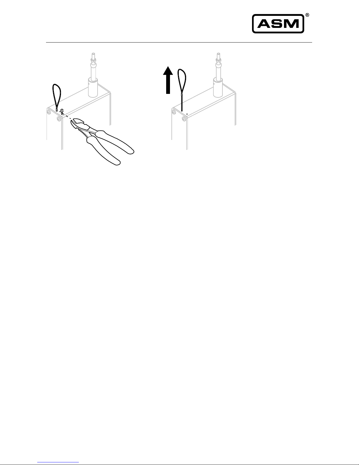
3.1 Delivery / shipment ......................................................................................................................... 7
3.2 Mechanical installation ................................................................................................................... 9
3.3 Electrical connection .................................................................................................................... 16
3.4Operating temperature ................................................................................................................. 20
4Maintenance and disposal .......................................................................................... 21
4.1 Maintenance and repair ............................................................................................................... 21
4.2Disposal ........................................................................................................................................ 21
5Output specification .................................................................................................... 22
5.1 Measurement signal and range.................................................................................................... 22
5.2 Precision potentiometer ............................................................................................................... 23
5.3 Optical incremental output ........................................................................................................... 35
5.4 Optical absolute encoder ............................................................................................................. 45
5.5 Magnetic encoder ......................................................................................................................... 50
5.6 Output information ........................................................................................................................ 76
6EU Declaration of Conformity ..................................................................................... 83

posiwire®
Cable Extension Position Sensors
4
Version 4.1.0
www.asm-sensor.com
Pos: 6 /Bedienungs anleitungen/Mo dule Uni versal/Überschrifte n/Sicherheitshi nweise UE @ 6\mod_15076 30884828_78.doc x @ 48429 @ 1 @ 1
1 Safety instructions
Pos: 7 /Sicherheits hinweise/Sign alwörter und S ymbole UE @ 1\ mod_140014 0467807_78.doc x @ 9166 @ 2 @ 1
1.1 Signal words and symbols
Pos: 8 /Sicherheits hinweise/Sign alwörter @ 1 \mod_1400240 492762_78.docx @ 9385 @ @ 1
WARNING, Risk of Injury:
Indicates a potentially hazardous situation, which, if not avoided, could result in serious
injury or property damage.
WARNING, Risk of Personal Injury or Death:
Indicates a situation that can result in serious personal injury or death if not properly
avoided.
WARNING, Risk of Personal Injury or Death:
Indicates a situation that can result in moderate personal injury or death if not properly
avoided.
WARNING, Risk of Personal Injury:
Indicates a situation that can result in minor personal injury if not properly avoided.
WARNING, Risk of Property Damage:
Indicates a situation that can result in minor to major property damage if not properly
avoided.
Product liability
• Disregarding the following instructions may result in malfunction, damage to property and personal
injury and releases the manufacturer from product liability.
Pos: 9 /######## ### Seitenu mbruch ######## ########### ############## ## @ 0\mod _13535841688 94_0.docx @ 3 36 @ @ 1

posiwire®
Cable Extension Position Sensors
Version 4.1.0
www.asm-sensor.com
5
Pos: 10 /Sicherh eitshinweise/Allg_ Sicherheitshi nweise UE @ 0\mod_13853 98033298_78.d ocx @ 2610 @ 2 @ 1
1.2 General safety instructions
Pos: 11 /Sicherh eitshinweise/Sich erheitshinweis e_WS @ 5\ mod_1499329 320743_78.docx @ 44291 @ @ 1
Risk of crushing and cutting injury due to pre-tensioned spring being released
from housing when opened!
• Do not open the sensor.
Risk of cutting injury due to uncontrolled retraction of the cable
• Do not damage the measuring cable!
• Do not let the measuring cable and the cable fixing spring back uncontrolled!
• Do not exceed the maximum cable extension range!
• Do not bend the measuring cable!
• Do not let the measuring cable be dragged on objects!
Mechanical damage or destruction of the sensor
• Avoid impact and shock to the sensor.
• Do not allow the measuring cable to spring back uncontrolled.
• Do not pull out the measuring cable beyond the range of the sensor.
Malfunction due to the accumulation of dirt on the measuring cable
• Do not oil or lubricate the measuring cable.
Pos: 12 /####### #### Seitenumbru ch ####### ########### ############## ### @ 0\ mod_1353584168 894_0.docx @ 336 @ @ 1

posiwire®
Cable Extension Position Sensors
6
Version 4.1.0
www.asm-sensor.com
Pos: 13 /Sicherh eitshinweise/Bes timmungsge mäße Verwendung/ Bestimmungsg emäße Ver wendung UE @ 1\ mod_140014 2179648_78.d ocx @ 9192 @ 2 @ 1
1.3 Intended use
Pos: 14 /Bedienungs anleitungen/ Posiwire/Besti mmungsgemäße Verwendung W S @ 1\m od_14066365386 88_78.docx @ 16174 @ @ 1
posiwire® Cable Extension Position Sensors are used for linear position measurement of linear guided
objects by extending the measuring cable. The ranges for the measuring length as well as the information on
environmental compatibility and connection data given in the data sheet must be observed. The sensor is
used as intended if it is operated within its specified technical data and ambient conditions.
The installation and operating instructions supplied with the unit must be observed and all maintenance and
service work must be carried out. The data sheet of the respective sensor is part of this instruction manual. If
yet not available, it may be requested by stating the respective model number.
Pos: 15 /Sicherh eitshinweise/Bes timmungsge mäße Verwendung/Nic ht bestimm ungsgemäße Verwendung UE @ 1\mod _140014226273 7_78.docx @ 91 97 @ 2 @ 1
1.4 Unintended use
Pos: 16 /Bedienungs anleitungen/ Posiwire/Nicht b estimmungsge mäße Verwen dung WS @ 1\ mod_140663 6850781_78.doc x @ 16179 @ @ 1
Unintended use is if the sensor is operated outside of its specified technical data and ambient conditions.
The sensor must not be improperly mounted, operated or serviced. In addition, operation of the sensor in
faulty condition is prohibited.
Check whether the protection class of the sensor is suitable for the application.
Danger of personal injury and danger of property damage
• The danger of personal injury and danger of property damage due to a
malfunction of the sensor in machines or systems must be excluded by
additional safety measures.
• In safety-relevant applications, additional facilities shall be provided for
maintaining safety and preventing damage.
Pos: 17 /####### #### Seitenumbru ch ####### ########### ############## ### @ 0\ mod_1353584168 894_0.docx @ 336 @ @ 1

posiwire®
Cable Extension Position Sensors
Version 4.1.0
www.asm-sensor.com
7
Pos: 18 /Bedienungs anleitungen/ Posiwire/Transp ort und Lageru ng @ 6\ mod_150876882117 5_78.docx @ 4 9055 @ 1 @ 1
2 Transport and storage
Risk of damage to the measuring cable or cable fixing
• Do not lift the sensor by the cable or cable attachment
Observe storage and transport temperatures according to the operating temperature (see data sheet)
Max. rel. humidity 60%, condensation must be excluded
The device must be secured against slipping and tipping during transport.
Pos: 19 /Bedienungs anleitungen/M odule Uni versal/Überschrifte n/Montage, In betriebnahme UE @ 4\mod _1491474694256 _78.docx @ 38 324 @ 1 @ 1
3 Installation and initial operation
Pos: 20 /Bedienungs anleitungen/ Posiwire/Liefer umfang @ 2\ mod_1415609 118551_78.doc x @ 16784 @ 2 @ 1
3.1 Delivery / shipment
Unpacking
Do not unpack sensor by pulling cable or cable clip.
Shipment damages
Check sensor immediately for shipping damage. In case of any damage, please contact your supplier.
Removing kink protection / Shipment protection
The kink protection prevents the cable fixing from buckling and damaging the cable. Remove in the direction
of the cable.

posiwire®
Cable Extension Position Sensors
8
Version 4.1.0
www.asm-sensor.com
Transport protection (for some sensor models) prevents the measuring cable from being extracted before
mounting the sensor. Only remove immediately before mounting:
1. cut the crimped, short wire end directly at the sensor housing
2. pull the wire out of the case at the loop
For further transport, use the original packaging (if available) to avoid transport damage.
Shipment content
• Sensor
• Installation and operation manual
(connector not included in scope of delivery)
Pos: 21 /Bedienungs anleitungen/ Posiwire/Geg enstecker_ WS @ 5\mod_149 9239358285_78. docx @ 442 15 @ @ 1
Mating connectors
Delivery does not include female connectors for electrical connection.
They are available under the following order code:
90° female 8-pin connector DIN CONN-DIN-8F-W
Female 8-pin connector M12 CONN-M12-8F-G
90° female 12-pin connector DIN CONN-DIN-12F-W
Female 12-pin connector CONN-CONIN-12F-G
Pos: 22 /####### #### Seitenumbru ch ####### ########### ############## ### @ 0\ mod_1353584168 894_0.docx @ 336 @ @ 1

posiwire®
Cable Extension Position Sensors
Version 4.1.0
www.asm-sensor.com
9
Pos: 23 /Bedienungs anleitungen/ Posiwire/Montag e_man @ 3\ mod_145804 1468522_78.doc x @ 23241 @ 2 @ 1
3.2 Mechanical installation
Risk of injury from touching the moving measuring cable or moving parts
during operation
• Operate the sensor only with a suitable protective device (e.g. cable cover) to
prevent injury!
Choice of installation position
• Select a protected installation position for the measuring cable.
This prevents damage of the measuring cable.
• Preferably mount the sensor with the cable outlet pointing downwards.
This prevents liquids from entering through the cable outlet.
• Screw the sensor onto a flat surface or provide a three-point mounting.
This avoids distortion and damage to the sensor.
• In harsh environments provide protection for the measuring cable.
Cable travel should only be axial to the cable outlet - no misalignment is
allowed
• Cable misalignment shortens service life of sensor and causes error in
measurement. Warranty will not be granted for damage caused by misalignment.
Sensor with
horizontal extension
Sensor with vertical
extension
• If the measuring cable cannot be extended in the axial direction of the cable
outlet opening due to the measuring task, the SR2 cable pulley must be used.
• For special applications, extension cables with cable clips attached on both ends
are available.

posiwire®
Cable Extension Position Sensors
10
Version 4.1.0
www.asm-sensor.com
Fixing the sensor
Depending upon the sensor model, holes in the base plate, threads, mounting brackets or T-slots in the
sensor housing enable attachment of the sensor. Required dimensions are listed in the data sheet.
Mount the sensor on flat surface.
Use flat washers and/or screw protection if necessary.
The torques of the fixing screws depend on the material used (see p. 12).
Cable attachment device
The cable clip can be fastened as follows:
• M4 cable connection in cable outlet direction
The mounting of the M4 connection
is made with a through hole and a
M4 nut.
Do not rotate the M4 connection
during assembly, otherwise the
measuring cable will be twisted!
• Cable clip with Allen screw M5: standard fixing.
• Cable clip with attachment head (accessory GK1: metal, GK2: plastic): fast cable attachment, easy to
remove

posiwire®
Cable Extension Position Sensors
Version 4.1.0
www.asm-sensor.com
11
• Cable clip with magnetic clamp (accessory MAG1): with this device the sensor can be easily used at
several measuring points with ferromagnetic surface.
Cable clip attachment
The cable clip (see drawing above) can be opened for easy attachment of the measuring cable. If possible,
fasten cable fixing with cable in retracted position.
Mounting hints for unfavourable installation conditions
For example, fit a mounting loop and put it around your wrist. Do not remove the mounting loop until after
final installation.
Pos: 24 /####### #### Seitenumbru ch ###### ############ ########### ###### @ 0\ mod_1353584168 894_0.docx @ 336 @ @ 1
Danger of cutting injuries due to cable clips during cable connection
• Before connecting the cable clip into the fixture read the mounting instructions.

posiwire®
Cable Extension Position Sensors
12
Version 4.1.0
www.asm-sensor.com
Pos: 25 /Bedienungs anleitungen/ Posiwire/Anzugs momente @ 3 \mod_1458 045382302_78. docx @ 23317 @ @ 1
Fixing screws
WS31 / WS31C / WS42 / WS42C
Model
Screw material
Material
Torque
[Nm]
WS31 /
WS31C
M2.5 Mounting brackets
A2
0.25
WS31 /
WS31C
M3 Clamping claws
A2
0.5
WS31 /
WS31C
M4 Mounting brackets
A2
0.65
WS42 /
WS42C
M2.5 Mounting brackets
A2
0.25
WS42 /
WS42C
M3 Clamping claws
A2
0.5
WS42 /
WS42C
M4 Mounting brackets
A2
0.65
Pos: 26 /Bedienungs anleitungen/ Posiwire/Anzugs momente WS1 0 @ 3\mod _1458045971 049_78.docx @ 2 3322 @ @ 1
WS10, WS10ZG, WS10SG
Model
Screw
Screw
material
Torque
[Nm]
WS10
M5, 8 mm deep
A2
2,0
WS10ZG
M5, 8 mm deep
A2
2,0
WS10SG
M5, 8 mm deep
A2
2,0
Pos: 27 /Bedienungs anleitungen/ Posiwire/Anzugs momente WS1 7 @ 3\mod _1458046243 243_78.docx @ 2 3334 @ @ 1
WS17KT, WS19KT, WS21
Model
Screw
Screw
material
Torque [Nm]
WS17KT
M5
A2
2.5
WS19KT
M5
A2
2.5
WS21
M5
A2
2.5
Pos: 28 /####### #### Seitenumbru ch ####### ########### ############## ### @ 0\ mod_1353584168 894_0.docx @ 336 @ @ 1

posiwire®
Cable Extension Position Sensors
Version 4.1.0
www.asm-sensor.com
13
Pos: 29 /Bedienungs anleitungen/ Posiwire/Anzugs momente WS58C @ 3\ mod_1458046494 371_78.doc x @ 23346 @ @ 1
WS58C
Model
Screw
Screw
material
Torque
[Nm]
WS58C
M4, 5 mm deep
A2
1.0
Pos: 30 /Bedienungs anleitungen/ Posiwire/Anzugs momente WS6 0 @ 3\mod _1458046620 819_78.docx @ 2 3358 @ @ 1
WS60
Model
Screw
Screw
material
Torque
[Nm]
WS60
M8
A2
10.0
Pos: 31 /Bedienungs anleitungen/ Posiwire/Anzugs momente WS7. 5 @ 3\m od_14580467655 57_78.docx @ 23364 @ @ 1
WS7.5
Model
Screw
Screw
material
Torque
[Nm]
WS7.5
M5
A2
2.5
Pos: 32 /####### #### Seitenumbru ch ####### ########### ############## ### @ 0\ mod_1353584168 894_0.docx @ 336 @ @ 1

posiwire®
Cable Extension Position Sensors
14
Version 4.1.0
www.asm-sensor.com
Pos: 33 /Bedienungs anleitungen/ Posiwire/Anzugs momente WS6 1_85 @ 3\ mod_1458125 032438_78.docx @ 23407 @ @ 1
WS61, WS85
Model
Screw
Screw
material
Torque
[Nm]
WS61 (oval hole)
M5
A2
2.0
WS85
M6
A2
4.0
WS85 (oval hole)
M6
A2
3.0
Pos: 34 /Bedienungs anleitungen/ Posiwire/Anzugs momente WS1 2 @ 3\mod _1458046157 544_78.docx @ 2 3328 @ @ 1
WS12
Model
Screw
Screw
material
Torque
[Nm]
WS12
M5, 10 mm deep
A2
2.0
Pos: 35 /Bedienungs anleitungen/ Posiwire/Anzugs momente WS1 00M @ 3\m od_1458046393 356_78.docx @ 23340 @ @ 1
WS100M
Model
Screw
Screw
material
Torque
[Nm]
WS100M
M10
A2
20
Pos: 36 /####### #### Seitenumbru ch ####### ########### ############## ### @ 0\ mod_1353584168 894_0.docx @ 336 @ @ 1

posiwire®
Cable Extension Position Sensors
Version 4.1.0
www.asm-sensor.com
15
Pos: 37 /Bedienungs anleitungen/ Posiwire/SAB5 @ 4\mod_1 49155366461 3_78.docx @ 3836 2 @ @ 1
Cable dust wiper SAB5
1. Disassemble the aluminium washer (1) by removing the three M3 screws (3).
2. Remove the spiral wiper (4).
3. Fix the basic body at the cable outlet of the sensor by the set screw M3 (2).
Make sure that the sensor measurement cable is in centric position.
4. Thread the measurement cable into the spiral wiper.
Do not bend the measurement cable!
Do not let the cable spring back uncontrolled!
5. Assemble the aluminium washer.
Pos: 38 /####### #### Seitenumbru ch ####### ########### ############## ### @ 0\ mod_1353584168 894_0.docx @ 336 @ @ 1

posiwire®
Cable Extension Position Sensors
16
Version 4.1.0
www.asm-sensor.com
Pos: 39 /Bedienungs anleitungen/ Posiwire/Elektri scher Anschl uss @ 4\mod_1 491556449304 _78.docx @ 38381 @ 2 @ 1
3.3 Electrical connection
Damage or destruction of the sensor due to excessive operating voltage or
mounting error
• The applied operating voltage must not exceed the value specified in the data
sheet.
• Operate the sensor only within the limits specified in the data sheet.
• Connect to the power supply only by qualified personnel and in accordance with
the applicable safety regulations for electrical equipment.
• Do not connect or disconnect the sensor under voltage!
Corrosion in the sensor due to moisture penetration
• Use the sensor only according to IP protection
• Avoid crossing the dew point.
Connector Pin assignment
According to the definitions of the output types contained in the appendix.
Supply voltage
See specification in the data sheet of the sensor. The maximum operating voltage must not be exceeded.
Special Encoder
Special operating instructions for customized encoders must be observed.
The corresponding data sheets or encoder connection diagrams apply to output types not listed in the
connection table.
Connection example: current output 420A
To convert the 4 ... 20 mA signal into a voltage signal, it needs a load resistor RM (measuring resistor) as
shown in the diagram. The maximum value of RM depends on the cable resistance RL and the excitation
voltage UB:
RMmax = ((UB – 12 V)/0,02 A) – RL
With an excitation of 24 V DC and a cable resistance RL = 500 Ω a maximum value of RM = 100 Ω can be
used (see page 78) .
Pos: 40 /####### #### Seitenumbru ch ####### ########### ############## ### @ 0\ mod_1353584168 894_0.docx @ 336 @ @ 1

posiwire®
Cable Extension Position Sensors
Version 4.1.0
www.asm-sensor.com
17
Pos: 41 /Bedienungs anleitungen/ Posiwire/Montag e_02 @ 3\m od_145813043 7399_78.docx @ 23427 @ @ 1
Assembly of the couplings
90° female connector CONN-DIN-8F-W
1. Assemble O-rings (lubricate!) on shielding ring (7) and rotating hull (9).
2. Stringing parts and cut off projecting braiding. Note detail drawing of shielding! (See chapter
Electromagnetic Compatibility / EMC).
Shielding connected
Put shielding around shielding ring.
Shielding not connected
Cut off shielding and insulate with heat shrink tube.
3. Thread wires through housing, then assemble shielding ring, sealing ring and pinch ring. Turn on
pressing screw to fix the cable, solder wires.

posiwire®
Cable Extension Position Sensors
18
Version 4.1.0
www.asm-sensor.com
4. Assemble remaining parts according to diagram, fasten pressing screw.
5. Insert profile seal and fix female connector at male socket. Check that the profile seal is in the correct
position.
• The sensor protection class (IP) is only valid when the electrical plug is correctly
connected.
• To ensure sensor protection class assemble all connector seals carefully. The
connector is suitable for cable diameters of 6 to 8 mm.
• The sealing ring has to enclose the cable tightly (use heat shrink tube if
necessary).
• Four different directions of the angled outlet are possible (4 x 90°) by changing
the position of the rotating hull (part no. 9 in the upper drawing).
Pos: 42 /Bedienungs anleitungen/ Posiwire/CONN_M 12_8F-G @ 3\mod_145 8134092484_ 78.docx @ 23457 @ @ 1
Female connector CONN-M12-8F-G
1. Stringing parts.
2. Dismantle, expand shield and turn over the shielding ring.
3. Push isolating hull into the housing. Thread wires through housing, the assemble shielding ring, sealing
ring and pinch ring. Turn on pressing screw to fix the cable. Screw wires.
4. Screw insert into housing and fasten pressing screw.
• The sensor protection class (IP) is only valid when the electrical plug is correctly
connected.
• To ensure sensor protection class assemble all connector seals carefully. The
connector is suitable for cable diameters of 6 to 8 mm.
• The sealing ring has to enclose the cable tightly (use heat shrink tube if necessary).
Pos: 43 /####### #### Seitenumbru ch ####### ########### ############# #### @ 0\ mod_1353584168 894_0.docx @ 336 @ @ 1

posiwire®
Cable Extension Position Sensors
Version 4.1.0
www.asm-sensor.com
19
Pos: 44 /Bedienungs anleitungen/ Posiwire/CONIN _F12_F-G @ 3\mod_14581 34331199_78. docx @ 23462 @ @ 1
Female connector CONN-CONIN-12F-G
1. Slide the adaptor pos. 1, the sleeve nut pos. 2, the sealing element pos. 4 with sealing ring pos. 3 onto the
cable.
2. Dismantle the outer sheath of the cable at a length of 23 mm.
3. Turn the shielding braid 90° up, move the shielding ring pos. 5A with a little rotation over the plastic film
resp. the cotton mesh but under the shielding braid; cut off the shielding braid flushing with the outer
diameter of the shielding ring pos. 5A.
4. Cut off plastic film, filler and inner isolation.
5. Strip the wires a length of 3,5 mm, twist (and tin).
6. Solder, crimp or screw the wires to the contacts.
7. Insert distance hull pos. 6.
8. Move insert pos. 7 and distance hull pos. 6 into the insert hull pos. 8; please see to it that the desired code
notch of the insert pos. 7 is inserted correctly into the code bar.
9. Push in the cable with shielding and sealing unit.
10. Screw the adaptor pos. 1 tight!
• The sensor protection class (IP) is only valid when the electrical plug is correctly
connected.
• To ensure sensor protection class assemble all connector seals carefully. The
connector is suitable for cable diameters of 6 to 8 mm.
• The sealing ring has to enclose the cable tightly (use heat shrink tube if necessary).
Pos: 45 /####### #### Seitenumbru ch ####### ########### ############## ### @ 0\ mod_1353584168 894_0.docx @ 336 @ @ 1

posiwire®
Cable Extension Position Sensors
20
Version 4.1.0
www.asm-sensor.com
Pos: 46 /Bedienungs anleitungen/ Posiwire/WS_EMV @ 6\mo d_15076495824 88_78.docx @ 48479 @ @ 1
Electromagnetic Compatibility (EMC)
The electromagnetic compatibility of posiwire® Cable Extension Position Sensors is influenced by the
sensor wiring.
Recommended wiring:
• Single shielded sensor cable with twisted pair conductors for power supply and signal output.
• Connect the cable shield to ground on one side of the control cabinet. Connect the shield connection
over a large area using cable clamps before or at the cable entry into the control cabinet. When
preassembled cables are delivered, the screen is not connected to the housing on the sensor side.
• Do not install sensor cables in the immediate vicinity parallel to power conducting conductors such as
motor or contactor control cables (separate cable ducts for signal and power cables).
Additional measures may be necessary when used in systems with highly
interference-prone components such as frequency inverters
• Use cables with an outer shield and twisted and shielded conductors in pairs.
• Install the cables in metal cable ducts connected to ground.
Pos: 47 /Bedienungs anleitungen/ Posiwire/Arbeitst emperatur_Ü bersicht_WS @ 6\mod_151 0148338435_ 78.docx @ 4947 5 @ 2 @ 1
3.4 Operating temperature
The operating temperature of a sensor depends on the sensor type and encoder technology used:
posiwire® WS31 (Incremental encoder)
posiwire® WS42 (Incremental encoder)
0 … +60°C
posiwire® WS31, WS31C (Potentiometer)
posiwire® WS42, WS42C (Potentiometer)
-15 … +60°C
posiwire®WS10, WS10SG, WS10ZG
(Incremental encoder)
posiwire® WS12 (Incremental encoder)
-10 … +70°C
posiwire® WS61
posiwire® WS85
posiwire® WS21
-40 … +85°C
all other sensors
-20 … +85°C
Pos: 48 /####### #### Seitenumbru ch ####### ########### ############## ### @ 0\ mod_1353584168 894_0.docx @ 336 @ @ 1
Other manuals for posiwire
1
Table of contents
Other ASM Accessories manuals

ASM
ASM positape WBT Series User manual

ASM
ASM POSITAPE WB Series User manual

ASM
ASM posiwire User manual

ASM
ASM posiwire WST Series User manual

ASM
ASM POSIROT Series User manual

ASM
ASM POSIROT PRAS User manual

ASM
ASM PRDS-CANOPR User manual

ASM
ASM posirot PRAS Series User manual

ASM
ASM posirot PRAS Series User manual

ASM
ASM Posihall PH36 Owner's manual
Popular Accessories manuals by other brands

Thermo Neslab
Thermo Neslab CryoCool Series Instruction and operation manual

ZWO
ZWO EAF Detailed Installation and Operations Manual

Niles
Niles SRK-1W Specification sheet

Larson Electronics
Larson Electronics EXP-MS-N4X-AT-HV instruction manual

Lifetime
Lifetime 1529 owner's manual

Pebble
Pebble Smart Installation and training