manuals.online logo
Brands
  1. Home
  2. •
  3. Brands
  4. •
  5. ASROCK
  6. •
  7. Computer Hardware
  8. •
  9. ASROCK ROMED8-2T User manual

ASROCK ROMED8-2T User manual

ROMED8-2T
Quick Installation Guide
www.asrockrack.com
4
2
P/N: 15G065153000AK V1.0
Install the Server Board
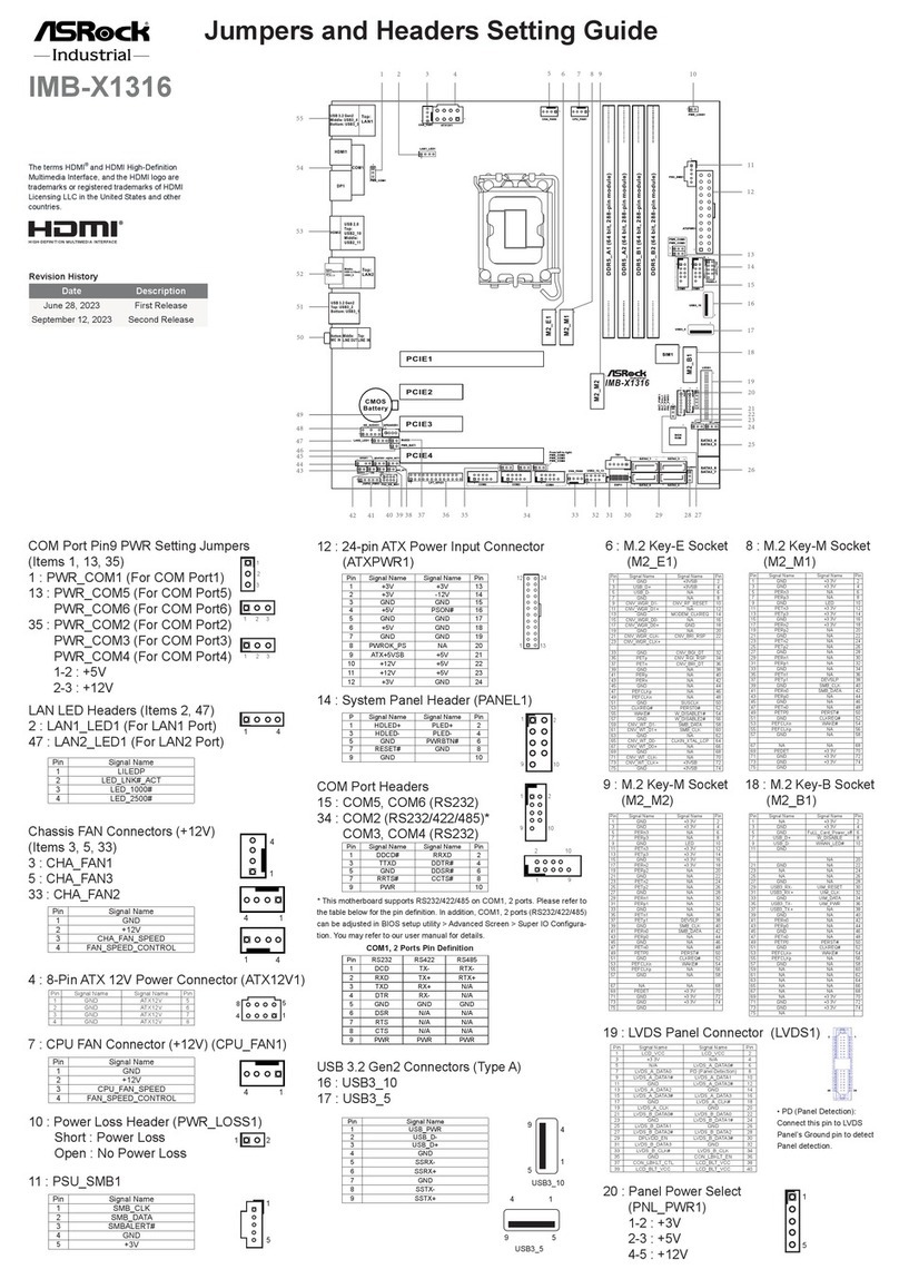
Motherboard Layout
Jumper Settings (PE8_SEL / PE16_SEL)
The server board User's Manual is available for download from the ASRock Rack's o󰀩cial website
at http://www.asrockrack.com.
Take note of the following precautions before you install server board components or change any
server board settings.
1. Unplug the power cord from the wall socket before touching any components.
2. To avoid damaging the server board’s components due to static electricity, NEVER place your
server board directly on the carpet or the like. Also remember to use a grounded wrist strap or
touch a safety grounded object before you handle the components.
3. Hold components by the edges and do not touch the ICs.
4. Whenever you uninstall any component, place it on a grounded anti-static pad or in the bag
that comes with the component.
5. When placing screws into the screw holes to secure the server board to the chassis, please do
not over-tighten the screws! Doing so may damage the server board.
1
1Insert the server board into the chassis.
2Ax the screws clockwise into the mounting holes in
all of the corners of the server board.
Do not over-tighten the screws
When the jumper cap is placed on the pins,
the jumper is “Short”. If no jumper cap is
placed on the pins, the jumper is “Open”.
e illustration shows a 3-pin jumper whose
pin1 and pin2 are “Short” when a jumper cap
is placed on these 2 pins.
I/O Panel3
2
3
14
5
678
Remove the standoff
from the chassis
Rear I/O
Attention! Before installing this motherboard, be sure to
unscrew and remove the standos at the marked location,
under the motherboard, from the chassis, in order to avoid
electrical short circuit and damage to your motherboard.
*15G065153000AK*
No. Description No. Description
1 UID Switch (UID1) 5 LAN RJ-45 Port (IPMI_LAN1)
2VGA Port (VGA1) 6 10G LAN RJ-45 Port (LAN1)
3 Serial Port (COM1) 7 10G LAN RJ-45 Port (LAN2)
4 USB 3.1 Gen1 Ports (USB3_1_2) 8 USB 3.1 Gen2 Port (USB31_TC_1)
PE8_SEL PE16_SEL PCIE2 M2_1 SATA_4_7 OCU1 &
OCU2
O X X X
O O O X
X O O O
X X X O
(x16)
(x8)
24.4cm (9.6 in)
30.5cm (12.0 in)
ATXPWR1
2
VGA1
COM1
DDR4_D1 (64 bit, 288-pin module)
DDR4_C1 (64 bit, 288-pin module)
DDR4_B1 (64 bit, 288-pin module)
DDR4_A1 (64 bit, 288-pin module)
DDR4_E1 (64 bit, 288-pin module)
DDR4_F1 (64 bit, 288-pin module)
DDR4_G1 (64 bit, 288-pin module)
DDR4_H1 (64 bit, 288-pin module)
ATX12V1
PCIE6
PCIE7
3
4
5
7
USB 3.1 Gen1
T: USB2
B: USB1
IPMI_LAN
LAN1
LAN2
UID1
USB3_3_4
OCU1
OCU2
SATA_0_3
SATA_4_7
GFX_12V1
PCIE4
PCIE5
PCIE2
PCIE3
PCIE1
M2_2 M2_1
NUT30
NUT42
NUT60
NUT80
NUT30_2
NUT42_2
NUT60_2
NUT80_2
BAT1
1
AUX_PANEL1
HDLED RESET
PLED PWRBTN
PANEL1
1
1
TPM1
1
SPEAKER1
1
T 1
R
1
1
IPMB1
NMI_BTN1
1
CHASSIS_ID0
1
BMC_SMB_1
AST
2500
RoHS
ROMED8-2T
ATX12V2
FAN1
FAN2
FAN3
FAN4
FAN5
FAN7
BMC
F/W
8
9
10
11
12
14
15
16
18
19
22
23
242829
30
33 31
36
37
38
40
41
Intel
X550
LGA4094
Socket SP3
34
CLRMOS1
35
1
PSU_SMB1
1
NUT110_2
Dr.
Debug
(NCSI)
17
FAN6
25
USB31_TC_1
USB31_TC_2
USB3.1 Gen2
13
11
PE16_SEL
PE8_SEL
27 26
1
TPM_BIOS_PH1
1
NV12V_2
1
NV12V_4
1
NV12V_3
1
NV12V_1
1
T 1B
6
20
21
39
42
43
CPU1_HSBP1
32
1 PSU SMBus Header (PSU_SMB1)
2 ATX 12V Power Connector (ATX12V1)
3 ATX 12V Power Connector (ATX12V2)
4 ATX Power Connector (ATXPWR1)
5 USB 3.1 Gen1 Header (USB3_3_4)
6 NVDIMM Power Support Jumper (NV12V_1)
7 NVDIMM Power Support Jumper (NV12V_3)
8 System Fan Connector (FAN1)
9 System Fan Connector (FAN2)
10 OCuLink x4 Connector (OCU1)
11 System Fan Connector (FAN3)
12 OCuLink x4 Connector (OCU2)
13 M.2 Socket (M2_2) (Type 2230 / 2242 / 2260 / 2280 / 22110)
14 M.2 Socket (M2_1) (Type 2230 / 2242 / 2260 / 2280)
15 Mini-SAS HD Connector (SATA_0_3)
16 Mini-SAS HD Connector (SATA_4_7)
17 System Fan Connector (FAN4)
18 System Fan Connector (FAN5)
19 System Fan Connector (FAN6)
20 System Fan Connector (FAN7)
21 Graphics 12V Power Connector (GFX_12V1)
22 Speaker Header (SPEAKER1)
23 System Panel Header (PANEL1)
24 Auxiliary Panel Header (AUX_PANEL1)
25 Clear CMOS Pad (CLRMOS1)
26 PCIE2 x16 Selection Jumper (PE16_SEL)
27 PCIE2 x8 Selection Jumper (PE8_SEL)
28 ermal Sensor Header (TR1)
29 TPM Header (TPM1)
30 BMC SMBus Header (BMC_SMB1)
31 Intelligent Platform Management Bus Header (IPMB1)
32 CPU HP-SMBus Connector (CPU1_HSBP1)
33 Non Maskable Interrupt Button (NMI_BTN1)
34 underbolt AIC Connector (TB1)*
35 Chassis ID Jumper (CHASSIS_ID0)
36 Front Panel Type C USB 3.1 Gen2 Header (USB31_TC_2)
37 2 x 288-pin DDR4 DIMM Slots (DDR4_B1, DDR4_D1)**
38 2 x 288-pin DDR4 DIMM Slots (DDR4_A1, DDR4_C1)**
39 TPM-SPI Header (TPM_BIOS_PH1)
40 2 x 288-pin DDR4 DIMM Slots (DDR4_E1, DDR4_G1)**
41 2 x 288-pin DDR4 DIMM Slots (DDR4_F1, DDR4_H1)**
42 NVDIMM Power Support Jumper (NV12V_4)
43 NVDIMM Power Support Jumper (NV12V_2)
ROMED8-2T
Quick Installation Guide
www.asrockrack.com
8LAN Port LED Indications
6Install the Power Cables
IPMI LAN Port
ACT/LINK LED
SPEED LED
LAN Port
3V
3V
GND
GND
5V
5V
GND
PWROK_PS
5VSB
12V
12V
3V
121
13 24
3V
-12V
GND
PSON#
GND
GND
GND
5V
5V
5V
GND
N/A
7Install the Memory
10 M.2_SSD (NGFF) Module Installation
System Panel Auxiliary Panel
9Headers
LAN Port
1
2
3
Find the corresponding nut location to be used.
Move the stando based on the module type and
length.
Peel o the yellow protective lm on the nut. Hand
tighten the stando into the desired location.
Gently insert the M.2 module into the slot.
Tighten the screw with a screwdriver to secure
the module into place. Please do not overtighten
the screw.
4
5
4
8
1
5
12V
GND
5Install the Processor and Heatsink
We recommend using the CPU Installation tool to avoid CPU pin-bent problem.
Activity / Link LED Speed LED
Status Description Status Description
O No Link O 10M bps connection or no
link
Blinking Yellow Data Activity Yel low 100M bps connection
On Link Green 1Gbps connection
Activity / Link LED Speed LED
Status Description Status Description
O No Link O 100Mbps connection or
no link
Blinking Yellow Data Activity O 1Gbps connection
On Link Green 10Gbps connection
12
34
GND
12V
GND
SMB_CLK
SMB_Alert
CASEOPEN
1
SMB_DATA
+3VSB
LAN1_LINK
LED_PWR
LAN2_LINK
LED_PWR
+5VSB
GND
GND
LOCATORLED1+
LOCATORLED1-
LOCATORBTN#
System Fault LED-
AB
CD
System Fault LED+
E
GND
RESET#
PWRBTN#
PLED-
PLED+
GND
HDLED-
HDLED+
1
GND
3
2
4
5
BCDE A
1
1
2
3
4
7
8
Locate the three torx screws on the CPU socket and
unscrew them according to the order A→B→C. Open
the rst retention cover.
Open the second bracket. Take out the internal
plastic cover.
Install CPU along with the carrier frame, do not
separate them. Please make sure the carrier frame
with CPU is closely attached to the rail frame while
inserting it.
Please make sure that the carrier
frame with CPU is closely attached to
the rail frame while inser ting it.
5
6
Install the carrier frame with CPU. Don’t separate them.
Carrier Frame with CPU
Rail Frame
Close the bracket that holds the CPU. Close the
retention cover. Fasten the torx screw according to the
order A→B→C.
123
Unlock a DIMM slot by
pressing the module clip
outward.
Insert the memory module. Lock the clip.
M2_1 :
1 2 3 4
A B C D
3cm 4.2cm 6cm 8cm
Type2230 Type 2242 Ty pe2260 Type 2280
M2_2 :
1 2 3 4 5
A B C D E
3cm 4.2cm 6cm 8cm 11cm
Type2230 Type 2242 Ty pe2260 Type 2280 Ty pe 22110
BCDE A
BCDE A
ABCDE
ABCDE 20o
NUT1NUT2DE
TPM-SPI
SPI_WP
SPI_CS
MISO
RSMRST#
TPM_CS#
SPI PIRQ
SPI_RST
MOSI
SPI_CLK
+3.3V
GND
SPI_HOLD
1
X
ACT/LINK LED
SPEED LED
LAN Port

Other manuals for ROMED8-2T

2

Other ASROCK Computer Hardware manuals

ASROCK athena A1 Kit User manual

ASROCK

ASROCK athena A1 Kit User manual

ASROCK PRO Series User manual

ASROCK

ASROCK PRO Series User manual

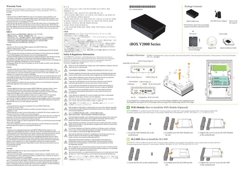
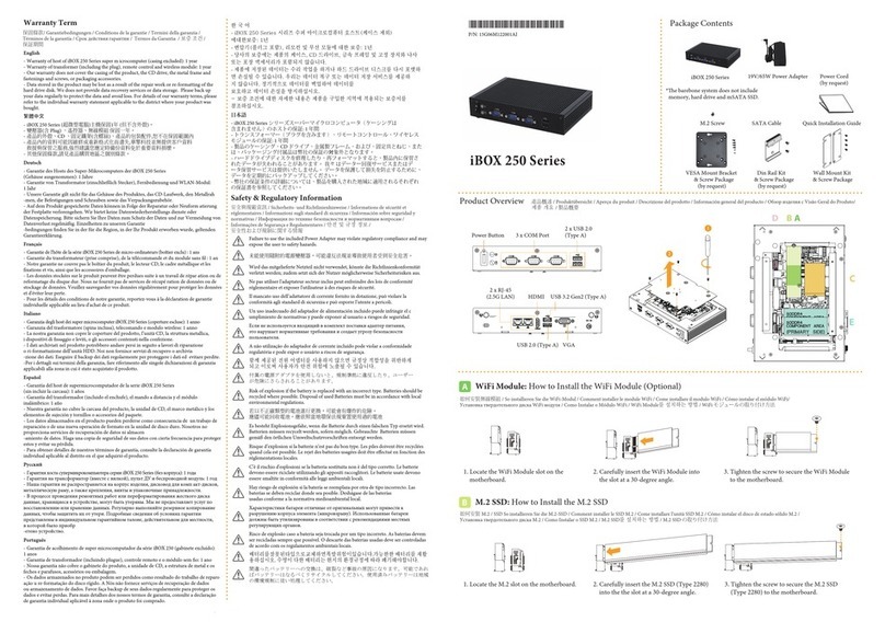
ASROCK iBOX 250 Series Instruction sheet

ASROCK

ASROCK iBOX 250 Series Instruction sheet

ASROCK Z68 EXTREME4 - ANNEXE 541 User manual

ASROCK

ASROCK Z68 EXTREME4 - ANNEXE 541 User manual

ASROCK IMB-1225 Service manual

ASROCK

ASROCK IMB-1225 Service manual

ASROCK SBC-250J Service manual

ASROCK

ASROCK SBC-250J Service manual

ASROCK WRX80 CREATOR User manual

ASROCK

ASROCK WRX80 CREATOR User manual

ASROCK H310CM-HDV User manual

ASROCK

ASROCK H310CM-HDV User manual

ASROCK ROMED8HM3 User manual

ASROCK

ASROCK ROMED8HM3 User manual

ASROCK iEPF-9000S-EX4 User manual

ASROCK

ASROCK iEPF-9000S-EX4 User manual

ASROCK iBOX-V2000M User manual

ASROCK

ASROCK iBOX-V2000M User manual

ASROCK Z390  Phantom Gaming 9 User manual

ASROCK

ASROCK Z390 Phantom Gaming 9 User manual

ASROCK NUCS BOX-1360P/D4 User manual

ASROCK

ASROCK NUCS BOX-1360P/D4 User manual

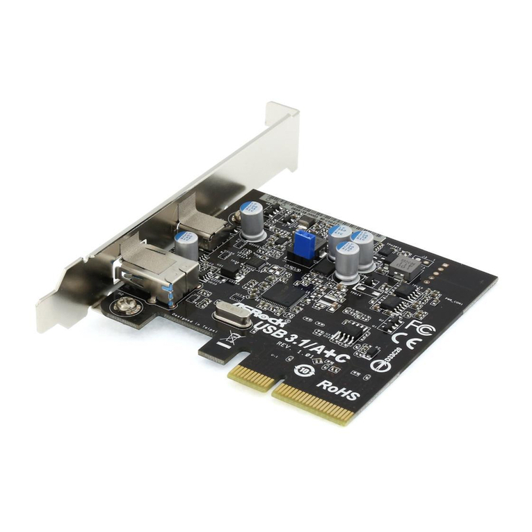
ASROCK USB 3.1/A+C User manual

ASROCK

ASROCK USB 3.1/A+C User manual

ASROCK LiveMixer B650 User manual

ASROCK

ASROCK LiveMixer B650 User manual

ASROCK APOLLO M1 User manual

ASROCK

ASROCK APOLLO M1 User manual

ASROCK SBC-250 Service manual

ASROCK

ASROCK SBC-250 Service manual

ASROCK B650E TAICHI User manual

ASROCK

ASROCK B650E TAICHI User manual

ASROCK NUC BOX-1360P/D4 User manual

ASROCK

ASROCK NUC BOX-1360P/D4 User manual

ASROCK B760 TW/D4 V2 User manual

ASROCK

ASROCK B760 TW/D4 V2 User manual

ASROCK IMB-156 Service manual

ASROCK

ASROCK IMB-156 Service manual

ASROCK Blazing Quad M.2 Card User manual

ASROCK

ASROCK Blazing Quad M.2 Card User manual

ASROCK STX-1001 User manual

ASROCK

ASROCK STX-1001 User manual

ASROCK A620M-HDV/M.2 User manual

ASROCK

ASROCK A620M-HDV/M.2 User manual

Popular Computer Hardware manuals by other brands

Cincoze DC-1000 user manual

Cincoze

Cincoze DC-1000 user manual

Ashly Keyboard Input Processor SC-44 operating instructions

Ashly

Ashly Keyboard Input Processor SC-44 operating instructions

Harman Kardon CITATION 7.0 owner's manual

Harman Kardon

Harman Kardon CITATION 7.0 owner's manual

Renesas R0E3308B0EPB00 user manual

Renesas

Renesas R0E3308B0EPB00 user manual

Freescale Semiconductor MSC8144E Reference manual

Freescale Semiconductor

Freescale Semiconductor MSC8144E Reference manual

Keithley DAS-1800ST Series user guide

Keithley

Keithley DAS-1800ST Series user guide

Renesas REG10J0083-0100 Tutorial manual

Renesas

Renesas REG10J0083-0100 Tutorial manual

Gemtek WL-316C user manual

Gemtek

Gemtek WL-316C user manual

Yamaha PLG150-DX Bedienungsanleitung

Yamaha

Yamaha PLG150-DX Bedienungsanleitung

StarTech.com PEXSAT34RH user guide

StarTech.com

StarTech.com PEXSAT34RH user guide

Kontron AdvancedTCA AT8901M user guide

Kontron

Kontron AdvancedTCA AT8901M user guide

POWERCOLOR DEVIL BOX User's installation guide

POWERCOLOR

POWERCOLOR DEVIL BOX User's installation guide

AMX AXU-MSP8 Schematic diagram

AMX

AMX AXU-MSP8 Schematic diagram

Octagon Systems 2050 PC/104 CPU Reference manual

Octagon Systems

Octagon Systems 2050 PC/104 CPU Reference manual

SeaLevel SIO-485.LPCI user manual

SeaLevel

SeaLevel SIO-485.LPCI user manual

Raspberry Pi PiCoolFAN4 user guide

Raspberry Pi

Raspberry Pi PiCoolFAN4 user guide

Optimus UMX-TEL operating instructions

Optimus

Optimus UMX-TEL operating instructions

Kontron CP308 user guide

Kontron

Kontron CP308 user guide

manuals.online logo
manuals.online logoBrands
  • About & Mission
  • Contact us
  • Privacy Policy
  • Terms and Conditions

Copyright 2025 Manuals.Online. All Rights Reserved.