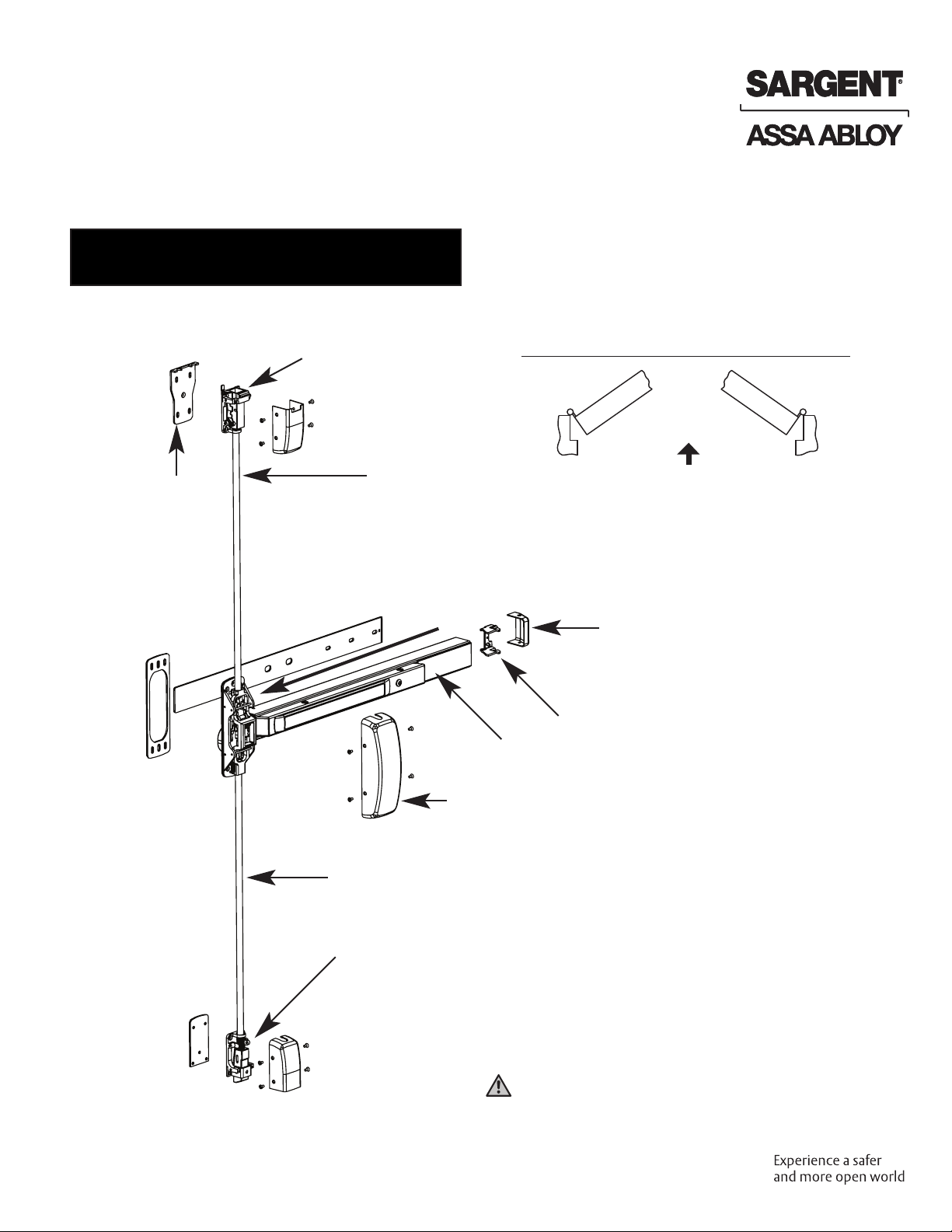
Assa Abloy SARGENT FM8700 User manual
Other Assa Abloy Door Opening System manuals

Assa Abloy
Assa Abloy DC340DA User manual

Assa Abloy
Assa Abloy SARGENT 1331 User manual

Assa Abloy
Assa Abloy NORTON RIXSON 5200 Series User manual

Assa Abloy
Assa Abloy RIXSON W73ER User manual

Assa Abloy
Assa Abloy DC135 Service manual

Assa Abloy
Assa Abloy Norton 8000 Series User manual

Assa Abloy
Assa Abloy Norton UniTrol UNI-1600BC Series User manual

Assa Abloy
Assa Abloy h.e.s. 9100 Series Manual

Assa Abloy
Assa Abloy Besam SL500 User manual

Assa Abloy
Assa Abloy Norton PR1601 User manual

Assa Abloy
Assa Abloy Besam SW300 Manual

Assa Abloy
Assa Abloy Corbin Russwin PED5800 Series User manual

Assa Abloy
Assa Abloy Sargent 2409 Series User manual

Assa Abloy
Assa Abloy NORTON RIXSON 5200 Series User manual

Assa Abloy
Assa Abloy Norton 6300 Series User manual

Assa Abloy
Assa Abloy besam PUSH-N-GO User manual

Assa Abloy
Assa Abloy NORTON RIXSON 1600 Series User manual

Assa Abloy
Assa Abloy Besam SP33-M User manual

Assa Abloy
Assa Abloy Norton 8000 Series User manual

Assa Abloy
Assa Abloy Norton 6011 Series User manual


Popular Door Opening System manuals by other brands


Stanley
Stanley MA900ñ Installation and owner's manual

WITTUR
WITTUR Hydra Plus UD300 Instruction handbook

Alutech
Alutech TR-3019-230E-ICU Assembly and operation manual

MPC
MPC ATD ACTUATOR 50 ATD-313186 Operating and OPERATING AND INSTALLATION Manual

GEZE
GEZE ECturn user manual

Chamberlain
Chamberlain T user guide