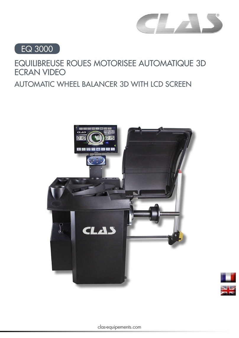
ATH-Heinl ATH 800 User manual

1
User’s Manual
Wheel Balancer
ATH 800
________________________________________________________
ATH-Heinl GmbH & Co.KG
Workshop technology
Kauerhofer Str. 2 - D92237 Sulzbach-Rosenberg
Tel. 0049 (0)9661 87764 00 - Fax 0049 (0)9661 87764 01
Email: info@ath-heinl.de Web: www.ath-heinl.de

2
Content
Subject to technical changes
1 Description of the machine
1.1 General information
1.2 Technical Data
1.3 Recommendations
1.4 Standard safety devices
2 Transport and assembling
3 Electrical connection
4 Wheel mounting
4.1 Fixing of shaft
5 Control Panel
6 Operation manual
6.1 Self test
6.2 Wheel mounting
6.3 Input of wheel parameters
6.4 Input of wheel parameters with automatic gauge
6.5 Input of wheel parameters with automatic gauge at ALU-S
6.6 Input of wheel parameters manual
6.7 Selection of balancing type
6.8 Standard mode “Dynamic”
6.9 Mode Static
6.10 Mode ALU 1-3
6.11 Mode ALU-S – Input manual
6.12 Mode ALU-S – Fixing of weights
6.13 Mode Motorcycle
7 Adjustment and calibration
7.1 System adjustment
7.2 Standard calibration
7.3 Service calibration
7.4 Calibration of automatic gauge
8 Errors
8.1 Different balancing values
9 Maintenance
9.1 Adjustment of driving belt tension
9.2 Changing fuses
10 Checking of position board
11 Installing of piezo element
12 Spare part list
Enclosure I - Exploded drawing
Enclosure II – Exploded drawing
Enclosure III - Electrical plan
EC Delaration of Conformity

3
1. Description of the machine
1.1 General information
This microprocessor controlled machine is intended for the balancing of tyres with a
weight of up to 60 kg. The key-controlled system enables a balancing of all types of
tyres from standard tyres up to tyres for motorcycles and racing cars. Due to special
functions it is also a balancing of tyres with non-standard rims possible.
General safety information
Only skilled persons are allowed to operate the machine.
If the operator makes unauthorized reconstructions and/or changes on the machine
the CE verification will be overridden and a liability of ATH-Heinl for damages, which
are resulting from this reconstructions/changes, is also excluded.
Only use the machine according to its intended and specified use.
If there are errors during operation or during the working process then the machine
must be switched-off from the current.
All electrical connecting and reconnecting works are only to be done by skilled
personal under consideration of the regulations of VDE and/or the responsible power
company.
As there is always a residual risk which can not be foreseen while working with
technical work equipment, there are different self-explanatory warning symbols
(triangle yellow/black) on the balancing machine.
This warning symbols signalise the operator a possible residual risk and shall provoke
a special care to avoid accidents and/or damages of the product to be treated.
In general the operator shall eliminate possible residual risks before by a proper and
careful attitute.
Here it must be especially considered:
•Always use correct and proper working materials.
•Wearing suitable protective clothing respectively protective agents (e.g.
protective glasses, ear protection, safety shoes and so on).
•Considering given informations, instructions and technical datas of the
machine producer respectively of the producer to be treated.

4
-The balancer shall only be used according to its intended use.
-Only skilled personal is allowed to operate the machine.
-Power-operated balancing machine are only allowed to be operated
in Germany with a protective bow.
-Safety devices are not allowed to be removed respectively taken
out of operation.
-Necessary reparation works are only allowed to be done by skilled
service personal. Unauthorized changes on the machine exclude
ATH-Heinl from liability for damages which are arising from this.
-Works on the electrical installation are only allowed to be done by
skilled electricians.
-The balancing machine is not allowed to be used in explosive
atmosphere (rooms).
-The balancing machine must be firmly fixed on the ground.
Further safety instructions in detail are indicated in the single chapters.

5
1.2 Technical data
Subject to technical changes
Maximum wheel weight
65 kg
Motor power
250 W
Power supply
230 V, 50 Hz
Unbalancing precision
1 g
Balancing speed
120 U/min
Rim diameter
10 - 24 Inches/ 254 - 610 mm
Rim width
1,5 - 15 Inches / 38 - 450 mm
Balancing time
7 s
Maximum wheel diameter
920 mm
Weight
105 kg
Dimensions
1100 x 700 x 1200
Noise level
<70 dB(A)
Working temperature
0 - 50 °C
Shaft Diameter
36 mm
Centering cones’ diameters 42 – 63 mm
61 – 79 mm
77 – 114 mm
107 – 154 mm
Special accessories available on request

6
1.3 Recommendations
- Read the operation manual carefully before operation.
- Keep the operation manual safe.
- To guarantee a correct operation, machine parts are not allowed to be removed or
modified. If reparations are necessary, the technical service has to be notified or
asked.
- Do not use compressed air while cleaning works.
- Clean the plastic faces with alcohol (do not use solvents).
- Take care that the wheel is fixed firmly on the adapter before starting balancing.
- The user is not allowed to wear clothing with sagging parts The user hast o take
care, that there are no further persons are nearby the machine during balancing
process.
- Do not put big parts on the machine, as this could affect the accuracy of
balancing.
- Do only use the balancing machine for purposes which are described in the
operation manual
- The balancing machine must be fixed firmly on the ground to achieve an exact
balancing result.
1.4 Standard safety devices
-Emergency stop button
-Protective bow is made of high-strength plastic. In form and size it is so
designed that the balancing weights will not expel but at most can fall on the
ground.
-A micro switch prevents that the machine can be operated when the protective
bow was not let down and the wheel will be decelerate when the protective bow
will be raised
-Electrical deceleration of the wheel.
2 Transport und assembling
To raise the machine, only the four support points which are foreseen for this are to be
taken. Do not raise under no circumstances the machine on other points as e.g. the
shaft, the display or the plate for accessories. The machine must stand on the
foreseen support points at the ground and must be fixed firmly.

7
3 Electrical connections
ATTENTION: The machine shall only be connected to the power supply by
skilled personal.
Before the machine will be connected to the power supply via a cable it has to be
checked if the supply voltage is identical with that indicated on the name plate. The
name plate is on the back of the machine. The connection shall correspond with the
power consumption of the machine. (see name plate).
- On the main connection cable of the machine has to be made a plug which
corresponds to the needed standard.
- We recommend to connect the machine via an own connection and an own
suitable line safety switch.
- If the machine will be connected directly (without plug socket) we recommend to
safe the line safety switch with a padlock so that only skilled persons have access
to it.
4 Wheel mounting
The standard equipment of the balancer is a shaft, pressure spring, 4 cones and a fast
clamping nut with pressure cab.
There are 3 possibilities to mount the wheel:
1. Mounting with suitable cone and fast clamping nut from outside (see Fig.1)
2. Mounting with suitable cone from inside with spring and with plastic cone from
outside (see Fig. 2-3)
3. Mounting with direct cone (available optional) either from outside or inside (see
Fig. 4-6)
The wheels have to be fixed with one of the delivered adapter (see enclosure). It has
to be considered that an unsufficient centering causes a wrong balancing result.
Fig.1 Fig.2 Fig.3 Fig.4 Fig.5 Fig.6.

8
4.1 Fixing of shaft
Before the thread shaft will be put on the balancing shaft it has to be checked, if the
area around the shaft and the thread shaft is clean. The thread shaft will be fixed to
the balancing shaft by a socket screw.
5 Control Panel
A Indicator: Position of inner unbalance B Digital display: Inner unbalance
C Lamp: Dynamic D Lamp: Static
E Lamp: ALU F Lamp: ALU-S
G Lamp: Optimization unbalance H Indicator: Position of weights
I Digital display: Static unbalance J Lamp: HID
K Lamp: Indicator mm or inch L Lamp: Motorcycle mode
M Digital display: Outer unbalance N Indicator: Pos. of outer unbalance
O Button Change of input parameters P Button: Plus-button
Q Button: Minus-button R Button: Enter- button
S Button: Change DYNAMIC/STATIC T Button: Recalculation
U Button: ALU program selection V Button: Motorcycle mode
W Optimization unbalance/Split program X Button:Indication exact unbalance
Y Button: emergency stop Z Button: Start-button
Note: Push the buttons only with the fingers. Do not use under no
circumstances the tongues for the compensating weights or other sharp
objects.

9
6. Operating Instructions
6.1 Self-test
After switching on of the balancer it makes a
self-test and changes then automatically to
the mode „Dynamic“
6.2
Wheel mounting
Choose a suitable cone to center the wheel on the balancer.(see also Fig. 1-6 on
page 7)
As shown below there are 2 simple methods to fix the wheel, either with inside cone
and pressure cab or without pressure cab with cone from outside.
6.3 Input of parameters
Except of the program "ALU-S", which needs 4 parameters, all other programs need
only 3 parameters. The parameters are shown in figure 10, figure 11 shows the
parameters for the program „ALU-S”.

10
6.4. Input of wheel parameters with automatic gauge
Inpu
t
whe
el
widt
h B
valu
e,
7.3.
Adjacent is shown the automatic
input of the three needed
parameters for dynamic, static
and ALU 1-3 mode.
Put the gauge as shown onto
the rim
During the movement of the
gauge the display goes out.
As soon as the gauge is at rest
then the determined values for
the distance (a) and the rim
diameter (d) will be indicated.
Following the display changes
automatically to the input for the
rim width (b).
This must be introduced
manually by means of the
buttons PLUS or MINUS.
figure16
Gauge back to „0“

11
6.5 Input of wheel parameters with automatic gauge in ALU-S
Adjacent is shown the automatic
input of the four needed
parameters for ALU-S mode.
In ALU-S mode must the gauge
be put onto the first desired
position on the rim for the weight
as shown adjacent and
confirmed by pressing ENTER.
The value for the first distance
measure (AI) will be memorized
with that and shown in the left
display.
Now the gauge is moved to the
second desired weight position.
The result for the second
distance measure (AE) is shown
in the right display.
Following it is possible to
indicate with the button the
display of the rim diameter (DI
and DE) respectively also to
alterate (+ and - ) it.

12
6.6 Input of parameters
Except of the program "ALU-S", which needs 4 parameters, all other programs need
only 3 parameters. The parameters are shown in figure 10, figure 11 shows the
parameters for the program „ALU-S”.
figure17

13
6.4 Selection of balancing type
Standard mode after switching
on of the balancer is the
dynamic mode. By pressing the
corresponding button can be
selected any mode as shown
adjacent.
OPT and Hidden are 2
additional functions.
OPT can be used in the
dynamic and in the static mode.
Hidden can be used in mode
ALU-S.

14
Or close the guard
Stop rotating measurement by opening the guard or
pressing STOP key in emergency
After correct input of
wheel parameters
Open the
guard
Measurement finished and the result is
displayed
Rotate the wheel,clamp a counterweight
of the displayed value eg:70g)on the
outside correction position
Keep rotating,clamp a counterweight of
the displayed value eg:40g) on the
inside correction position
Balancing finished
figure 19
6.8 Standard mode „Dynamic“
This function determines the parameter of the unbalance on the outer and inner side
of the mounted wheel and shows then the weight and the exact position of the
counterweight.
After the wheel is mounted properly and the wheel parameters are entered follow the
steps below described to balance the wheel.
The measurement is finished and the
results of the unbalance are shown in the
display.
Turn the wheel until all LED in the indicator
„outer“ illuminate and fix the
corresponding weight at the position „12
o clock“ (here 70 Gram).
Turn the wheel until all LED in the indicator
„inner“ illuminate and fix the
corresponding weight at the position „12
o clock“ (here 40 Gram).

15
Figure20
6.9
Static Mode
After dynamic mode measurement, it is possible to select static mode directly. The
balancer will automatically calculate the result of static mode.
If static mode was selected from the very beginning, follow the process below after
wheel installation and correct parameters input
The measurement is finished and the results of
the unbalance are shown in the display.
Turn the wheel until all LED in the indicator
„outer“ illuminate and fix the corresponding
weight at the position „12 o clock“ (here 60
Gram).
Stops while opening the protection or button “Stop”
Input wheel parameters
Or close wheel
protection

16
figure 18
6.10
ALU1 - ALU3 Modes
In the programs ALU 1-3 there
are different possibilities to
place the counterweights as
shown adjacent.
At the named symbols were
always taken the dimension as
for steel rims. Thereby can
occure inexactness when fixing
the weights.
After the balancing process are
to be fixed the corresponding
counterweights at the position
“12 o´clock” .
The below figure 18 shows
the dimension for fixing the
weights.

17
6.11 ALU-S Mode (input manual)
This special function can be used for Alu rims, if the standard Alu programs not make
a satisfactory result. By determining of two exact distance measures for fixing the
Weight there will be achieved considerably more exact results. (figure 1)
6.11 ALU-S Mode
By pressing the button ALU (out of the standard
modo 4x) you will reach the modo ALU-S.
Input of wheel parameter (see figure 2):
-Press button (change of wheel parameters)
and in the display appears Al (distance inner).
Determine by means of the gauge the dimension
and introduce it.
-Press button (change of wheel parameters)
and in the display appears AE (distance outer).
Determine by means of the gauge the dimension
and introduce it.
-Press button (change of wheel parameters)
and in the display appears DI (inner diameter).
Input diameter which is indicated on the rim.
-Press button (change of wheel parameters)
and in the display appears DE (outer diameter).
The program takes as standard value 80% of the
entered value for DI. That value can be changed
according to the type of rim.
Now the balancing process starts and therefore
the unbalance of the wheel will be determined.
Following the needed weights will be fixed at the
determined distance measures at the position 12
o´clock and a new balance process will be
started to achieve the balancing result.
By pressing the button FINE the residual
unbalance can be displayed in 1g-separation.
Figure 1
Figure 2

18
6.12 ALU-S Mode – Fixing of weights
After the measurements were introduced automatically as described in 6.5 or
manually as described in 6.11 the balancing process can be started.
After finish the balancing process the inner and outer unbalance will be indicated in
the display. (example here: 40 or 70 gram)
figure 25
The determined outer and inner unbalance will be
indicated in the left and right display (here: 40 and
70 gram).
Turn the wheel until all LEDs of the unbalance
display for OUTER illuminates. In the left display
the distance measure will be indicated
automatically (here: 170mm).
Move the gauge with the needed
counterweight (here 70g) into the rim until the
indicated distance measure (here 170 mm) in
the left display shows a value of „0“.
Now the weight is fixed at the indicated
position of the gauge.

19
Now the inner unbalance will be adjusted
Now turn the wheel until all LEDs oft he
unbalance display for INNER illuminates.
In the right display will be indicated the
distance measure automatically (here 83
mm).
Move the gauge with the needed
counterweight (here 40g) into the rim until the
indicated distance measure (here 83 mm)
shows a value of „0“.
Now the weight is fixed at the indicated
position of the gauge.

20
6.13 Split-Function
By means of the split function it is possible in the mode ALU-S by pressing the button
to fix the outer counterweight hidden behind the spokes.
The fixing of the weights is the same method as in the normal ALU-S program, the only difference is
that the weights were splitted and fixed between 2 proximate spokes.
After pressing the button „HID“ can be
introduced with the buttons + and – the
number of spokes.
Afterwards turn any spoke in the
position of the gauge.
Following press the button
„ENTER“ twice times, the value will be
memorized.
Any spoke in
position 12
o´clock.
Press button
„ENTER“ twice times
Start the balancing process,
afterwards the new calculated and
splitted weights will be indicated in
the right display.
Turn the wheel until all LEDs in the
unbalance display OUTER
illuminate. Here as described in
ALU-S fix the first weight.
Turn the wheel further until all LEDs
illuminate again and fix the second
weight.
The inner weight will be fixed
normally as in ALU-S.
Table of contents
Other ATH-Heinl Wheel Balancer manuals

ATH-Heinl
ATH-Heinl W102 User manual

ATH-Heinl
ATH-Heinl ATH W82 User manual

ATH-Heinl
ATH-Heinl W82 User manual

ATH-Heinl
ATH-Heinl W142 User manual

ATH-Heinl
ATH-Heinl W24 User manual

ATH-Heinl
ATH-Heinl W22 User manual

ATH-Heinl
ATH-Heinl W42 User manual

ATH-Heinl
ATH-Heinl W62 User manual

ATH-Heinl
ATH-Heinl W42 User manual

ATH-Heinl
ATH-Heinl ATH 1200 User manual