Atmos S 201 Thorax User manual

Operating instructions
English
ATMOS®
S 201 Thorax
312.1000.B
2014-08 Index: 33

2
Further information, accessories, consumables and
spare parts are available from:
ATMOS
MedizinTechnik GmbH & Co. KG
Ludwig-Kegel-Straße 16
79853 Lenzkirch
Deutschland / Germany
Tel. +49 7653 / 689-0
Fax: +49 7653 / 689-190
+49 7653 / 689-292 (Service Center)
www.atmosmed.de
Table of contents
5.0 Cleaning ...................................................................... 21
5.1 General information on cleaning and disinfection ........ 21
5.2 Cleaning the device surface......................................... 21
6.0 Maintenance and service........................................... 22
6.1 Basic information.......................................................... 22
6.2 Reprocessing ............................................................... 22
6.3 Battery handling ........................................................... 22
6.4 Exchange of fuses........................................................ 22
7.0 Trouble shooting ...................................................... 213
8.0 Accessories, consumables and spare parts ........... 24
8.1 Accessories.................................................................. 24
8.2 Consumables ............................................................... 24
8.3 Spare parts................................................................... 24
9.0 Technicalspecications............................................ 25
10.0 Checking / Reprocessing / Disposal ........................ 26
10.1 Checking ...................................................................... 26
10.2 Reprocessing ............................................................... 26
10.3 Disposal ....................................................................... 26
11.0 Notes on EMC........................................................ 27-29
General Standard Terms and Conditions
1.0 Introduction ............................................................... 3-6
1.1 Notes on operating instructions...................................... 3
1.2 Intended use .................................................................. 3
1.3 Contraindication ATMOS®S 201 Thorax........................ 3
1.4 Warnings ........................................................................ 3
1.5 Precautions .................................................................... 4
1.6 Function ......................................................................... 4
1.7 Explanation of pictures and symbols.............................. 5
1.8 Scope of supply............................................................. 6
1.9 Transport and storage .................................................... 6
2.0 For your safety ............................................................. 7
3.0 Setting up and starting up........................................ 8-9
3.1 Setting up ...................................................................... 8
3.1.1 Display / Operating elements ........................................ 8
3.2 Starting up...................................................................... 8
3.3 Functional test................................................................ 9
3.4 SD Card recording ......................................................... 9
4.0 Operation ............................................................... 10-20
4.1 Adjust vacuum.............................................................. 10
4.2 Suction procedure ........................................................ 10
4.3 Hose rinsing ................................................................. 10
4.4 Battery recharging........................................................ 10
4.5 Container...................................................................... 11
4.5.1 Filling the water lock..................................................... 11
4.5.2 Pop-off valve ................................................................ 11
4.5.3 Insertion of the container.............................................. 11
4.5.4 Hose holder at the container ........................................ 11
4.6 Connect hose set ........................................................ 12
4.7 Universal support (optional) ........................................ 12
4.8 Information on the display ........................................... 13
4.9 Display function........................................................... 13
4.9.1 Switch on menu........................................................... 13
4.9.2 Adjusting the vacuum.................................................. 13
4.9.3 Leakage test................................................................ 13
4.9.4 Keylock........................................................................ 14
4.9.5 Exchange of container ................................................ 14
4.9.6 Canister for gravity drainage system........................... 15
4.9.7 Switch off..................................................................... 15
4.10 Settings menu ............................................................. 16
4.11 Alarm........................................................................... 17
4.11.1 Alarm history ............................................................... 18
4.12 Flow, time and vacuum display .................................... 18
4.13 Insertion and removal of the micro SD card................. 20
4.13.1 Monitoring the progression of therapy via
micro SD card .............................................................. 20
4.14 Connection to the nurse call system ............................ 20

3
These operating instructions contain important notes on how to operate the ATMOS®S 201 Thorax
safely, correctly and effectively. Their reading helps to avoid risks, and also to reduce repair costs
and down-time. That increases, amongst other things, the reliability and service-life of the device.
These operating instructions serve not only for new operating personnel to be instructed in its use,
but also for use as a reference manual. Reproduction of these instructions – even in part – only with
the written permission of ATMOS.
These operating instructions must always be kept available near the device.
Care and safety inspections in conjunction with professional execution provide for operational safety
and readiness for use of your ATMOS®S 201 Thorax and are therefore a must besides regular
cleaning.
Repair work and safety inspections may be carried out only by expert personnel authorised by
ATMOS. By applying only original spare parts you will have the guarantee that operational safety,
readiness for work and the value of your ATMOS®S 201 Thorax will be preserved.
●The product ATMOS®S 201 Thorax bears CE marking according to the EC Directive of the
council for medical products 93/42/EEC and meets the basic requirements of annex I of this
directive.
●The product ATMOS®S 201 Thorax complies with all applicable requirements of the directive
2011/65/EC restricting the use of certain hazardous substances in electrical and electronic
equipment (“RoHS”).
●The declaration of conformity can be obtained on our website at www.atmosmed.com.
●The quality management system applied at ATMOS has been certi ed according to international
standards EN ISO 9001 and EN ISO 13485.
●Prior to start-up please peruse chapter 2.0 „For your safety“, in order to be prepared for any
possible dangerous situations.
1.0 Introduction
1.1 Notes on operating instructions
1.2 Intended use
1.2.1 Intended use of the ATMOS®S 201 Thorax
Main function: Mobile digital thoracic drainage system
Medical indication/application:
1. Restoring the natural vacuum and the natural uid balance in the pleural cavity after a pneumothorax or a pleural
effusion. This is achieved by drainage of air and secretion.
2. Drainage of secretion and air after surgical opening of the thorax.
Specicationofthemainfunction:
The digital drainage suction systems ATMOS S & E 201 Thorax are devices for mobile thoracic drainage. They are intended for
short-time (<30 days) application on human beings. They are portable, mains-independent and have an electronic monitoring sy-
stem with optical and acoustic status display. The products are used in unsterile condition, except the hose set and the collection
canister, which are sterile single-use products. Any trocars and catheters may be used which their manufacturers have intended
for use in thoracic drainage.
Patient group:
Patients with thoracic injuries who need pleural cavity drainage for maintaining the lung function. Furthermore, it is used for pati-
ents who had a surgical intervention which requires the drainage of blood and secretion from the thoracic cavity.
Application organ: Thorax
Application duration:
Under normal condition it is intended for continuous application over a period of less than 30 days (short-term).
Application environment:
Application environment is the clinical area. The application of the vacuum unit may only be performed by healthcare professio-
nals. Secretion canister and drainage hose are sterile single-use products which are used in a sterile surgical environment.
The product is: Active
Sterility: Not for the basic unit
Single-use product/reprocessing: Reprocessing for basic device

4
1.4 Warnings:
●Patient hose clamp must remain open during drainage operation.
●The device is not for use while bathing, showering nor suitable for a hazardous explosive environment.
●Do not use this device in MRI (Magnetic Resonance Imaging).
●Do not dry the device with microwaves.
●Chest hoses should not be clamped except when changing the canister. In the event of an airleak, clamping chest
hoses could lead to a tension pneumothorax.
●The ATMOS®S 201 Thorax must remain in an upright position during use.
●The patient should be regularly monitored according to internal hospital guidelines.
●ATMOS®S 201 Thorax is a medical device that requires special safety precautions and must be installed and
placed in operation in accordance with the attached EMC information. Portable and mobile RF communication devices
(mobile telephones) can affect the drainage system.
●A replacement device must always be available for patients for whom a breakdown of the device can lead to a critical situation.
● Do not separate patient hose in-line connector prior to clamping off patient hose rst.
●Do not keep patient hose clamp closed during drainage collection or patient transport.
● Please note that when the set pressure is -50 mbar or higher this high pressure can cause pain or injuries to the patient.
1.2.2 Intended use of the secretion canister for ATMOS®S 201 Thorax
Name: Sterile secretion canister for the exclusive connection to the ATMOS®E / S 201 Thorax.
Main functions:
Forwarding of the created vacuum into the drainage hose and nally into the patient side drain.
Collection of the exhausted secretion.
Med. indications/ application: Secretion canister for the connection to a digital device for mobile thoracic drainage.
Specicationofthemainfunction:
The vacuum generated by the pump evacuates air and secretion out of the drain. The secretion is collected in the secretion canister
whose lling quantity is 2 l. A bacterial lter prevents the potential contamination of the room and the device by bacteria. Additionally
it prevents the accidental intrusion of secretion into the pump head. A sterile tubing system provides the vacuum for the patient side
drain. A direct connection to the patient doesn’t exist. With the support of the test measuring hose inside of the tubing system, which
is also provided with a lter, the actual vacuum on the drain will be measured. Furthermore the measuring hose is also responsible
for the ushing of the secretion hose with atmospheric air.
Application organ: Thorax
Application time: Short-term use on the patient (< 30 days).
Application site: Application environment is a clinical area. The application of the canister may only be applied by healthcare
professionals. The secretion canister and the drainage hose are sterile and disposable and can be applied in the sterile OT area.
Contraindications: No application of the canister with other low vacuum devices than ATMOS®E / S 201 Thorax.
The product is: □ active X not active
Sterility: Sterile
Single use product / reprocessing: Sterile single use product
1.3 Contraindications of ATMOS®S 201 Thorax
In ambulances in service and in the home care eld which is not supervised by healthcare professionals.

5
1.6 Function
The ATMOS S 201 Thorax is a particularly useful small suction
unit. The device is operated by an electromotive, maintenance-
free piston pump. During operation the pump creates a vacu-
um in the hose system and in the collection jar, with the help of
which secretions can be sucked through the set of hoses.
The pump switches off after creation of the pre-adjusted
vacuum and switches on again only, when the vacuum lies
below a certain tolerance.
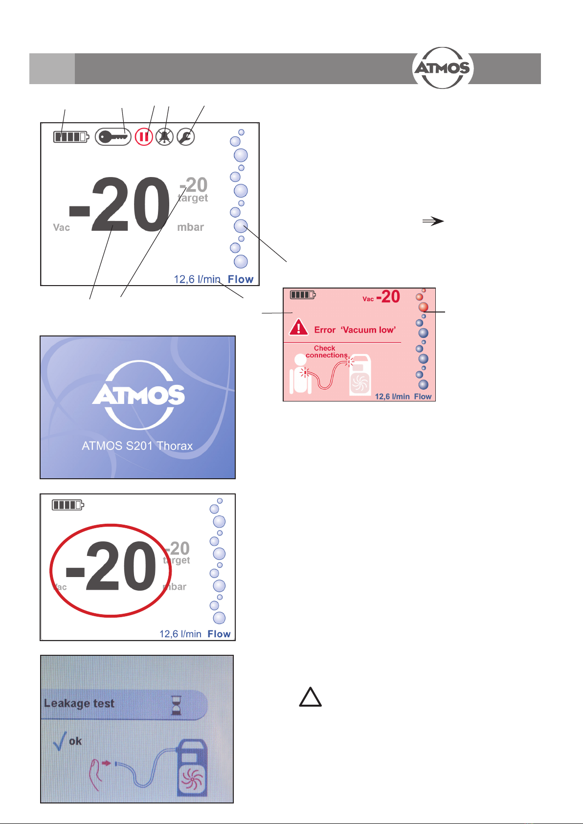
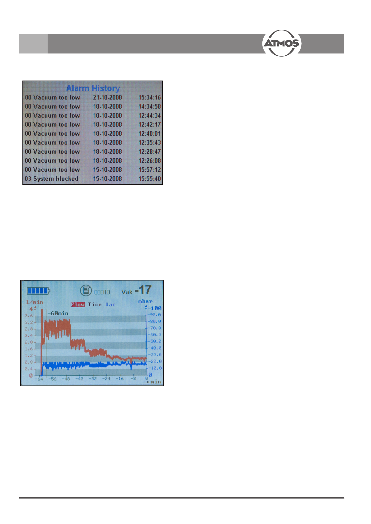
The real-time measured ow is shown as numerical value. At
one keypress ow data from up to 12 days are shown in a
graphic.
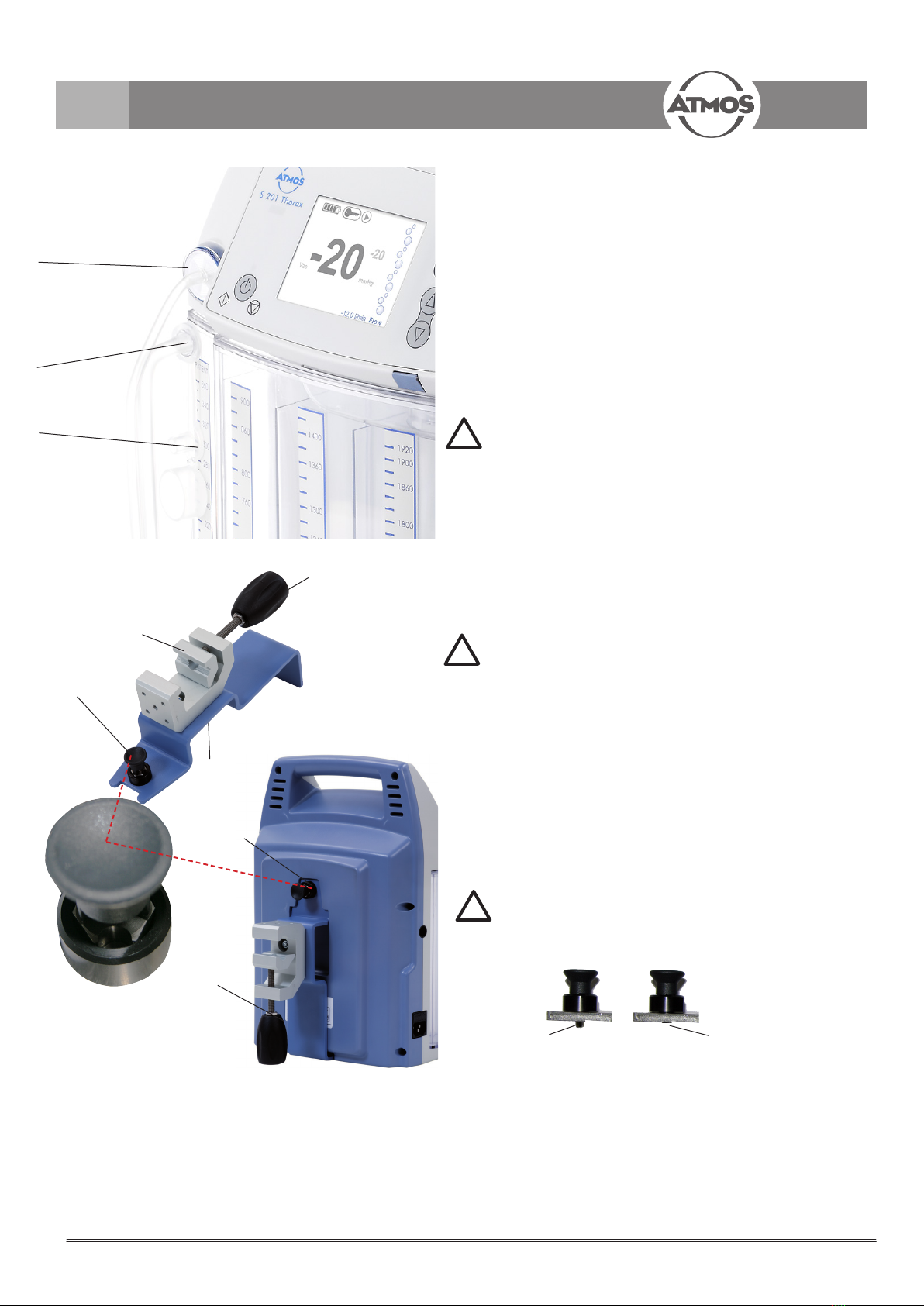
The secretion is collected in the collection jar, the capacity of
which is 2l. The vacuum at the trocar is measured by means of
the measuring pipe in the set of hoses. The nal vacuum can
be adjusted with the buttons on the operating foil. If required,
the air-ow rate is automatically adjusted. The device adjusts
and keeps the pre-adjusted vacuum automatically in case the
negative pressure in the pleural cavity varies. In this case the
pump starts to balance the negative pressure until the pre-ad-
justed vacuum is reached again and then switches off. These
compensation values, which may vary heavily, can easily be
read on the display. At regular intervals the device rinses the
suction hose with air so that deposits in the suction hose are
avoided and it prevents secretion from penetrating the
measuring channel.
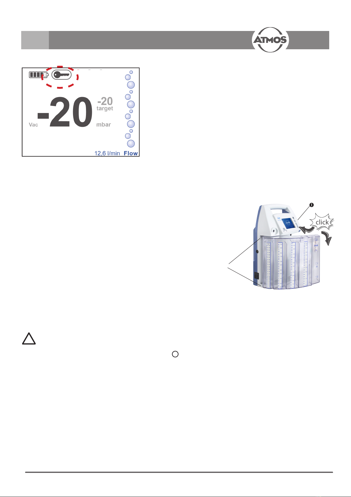
The device is tted with a rechargeable battery. A micro-
processor controlled electronic charging unit in the suction
device guarantees the safe charging of the battery, and thus
overcharging of the battery is avoided. In addition a bacterial
lter located in the cover of the collection jar prevents the entry
of bacteria and secretion into the interior of the device.
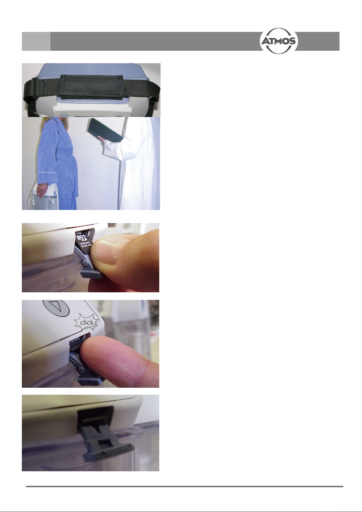
There is a carrying strap available for mobile use. A practical
carrying bag and a bed mounting are accessories that can be
ordered.
1.0 Introduction
1.5 Precautions
●Federal (U.S.A.) law restricts this device to sale by or on
the order of a physician.
●Cointainer and hose set are for single patient use and for
one time patient connection only.
●Do not resterilize this device. Container and hose are
single-use products, there is a high risk of infection in
case of re-use. The container cannot be emptied .
●Air vent must remain closed at all times when not in use.
●All hospital protocols for disposal handling and infection
controI should be carefully followed.
●The function of the device must be checked prior to use
(see chapter 3.0 – Setting up and starting up; section
3.3 Functional test)
●When a thoracic catheter is connected leaky connections
may result in an incorrect evaluation of air leaks from the
lung and delay treatment time. Therefore check that all
the connections are airtight to prevent air from entering
from the atmosphere.
●During set up, an incorrectly positioned drainage system
and patient tube may impair uid and air evacuation.
Total obstruction of uid and air evacuation can cause
an increase in positive pressure and possible tension
pneumothorax. Therefore position the drainage system
below the level of the patient`s chest and check that the
patient tube does not form loops or kinks, impairing
drainage of uid and air.
●General. Check that all the connections are airtight.
If the thoracic drainage unit tips over it is advisable to
set it up right again to guarantee operation and to be
able to re-determine the volume and appearance of the
drained uid. If there is the slightest uncertainty about
the operation of the drainage system after it has tipped
over, it is recommended that a new drainage system be
installed to ensure the patient‘s safety.
● Keep the AC adapter connector away from moisture.
●Keep the power cord away from hot surfaces.
● Do not overll water seal above the 2cm ll line.
● Water seal must be lled to prescribed level prior to use
and should be checked regularly to con rm proper
operation.
● Use only pre-packaged sterile uid for lling the water
seal.
●When inspecting the collection chamber routinely
check the volume and appearance of the drained uid
and inform the responsible clinician of abnormalities.
Exceeding the recommended collection volume can
cause obstruction of uid and air evacuation and may
therefore result in an excess pressure pneumothorax.
Always replace the canister when the maximum volume
is reached to ensure the patient`s safety. Replace chest
drain if damaged. Patient tube connections and water
seal, should be checked regularly to conrm proper
operation.
a.) Installation. The product must be used at room
temperature and should not be placed in direct sunlight
as this may result in measurement errors.
In case of noncompliance and misuse of the ATMOS S 201
Thorax any guarantee claims shall expire and ATMOS Medizin-
Technik GmbH & Co. KG assume no liability.
2

6
1.7 Explanation of pictures and symbols
1.0 Introduction
!
■
●
→
click
Pictures contained in this manual
Warning,
special diligent notice !
Short cuts / symbols contained in this manual
Please press where
the dot indicates
Subnumeration
Numeration
General information
Follow the arrows whilst
proceeding, sequence
Replace
Check
Please read,
important information
Move, plug ... in this
direction
Engage,
check correct t
Turn, shift ... in this
direction
Important information
Operating keys / symbols of the ATMOS S 201 Thorax
Serial number
Order number
Manufacturing date
The CE sign shows that this product
meets the appropriate requirements of
the EC guidelines.
Fuse
Protection class II
Application part type CF, debrillator-proof,
recovery time: 10 sec
REF
SN
OFF = long keypress
(supply,
disconnection
from the mains)
ON = short keypress
(supply, connection to
mains)
Adjustment keys ▲▼
Reset / Enter
Flow
Please observe operating instructions!
This product is not re-sterilisable.
Repeated reuse of components which
are marked with a is forbidden. In
case of repeated reuse these compo-
nents lose their function and there is a
high infection risk.
2
2
Sterile unless package
is damaged or open

7
1.0 Introduction
1.8 Scope of supply
●Prior to dispatch, this ATMOS device was subjected to an extensive functional test and has been carefully packed.
Nevertheless, please compare the contents of the shipment on completeness immediately upon receipt (see delivery note).
1.9 Transport and storage
● The transport of the device may be effected only in a
dispatch carton upholstered and offering sufcient pro-
tection.
● Please document and report damages in transit imme-
diately. For complaints or return deliveries, please use
the enclosed form QD 434. The form QD 434 can also
be downloaded from the internet www.atmosmed.de.
●The unit must be allowed to stand for up to six hours at
room temperature prior to starting up for the rst time
following transport at temperatures below freezing. The
unit may not be operated if it has not acclimatised as
this might damage its piston.
●Ambient conditions:
Transport/Storage: -10...+50°C;
30...95 % air humidity
non-condensing
at air pressure 500...1060 hPa
Operation and +10...+35°C;
battery charging: 30...95 % air humidity
non-condensing
at air pressure 700...1060 hPa
Basic device
Container set,
sterile packed
(Must be ordered
separately!)
Operating
instructions
Hose set
sterile packed
(Must be ordered
separately!) Power cord
Micro SD card

8
!
For your safety
2.0 For your safety
Dispose of the packing material in a proper manner.
Before the device is connected a check must be made to
see that the mains voltage and mains frequency given on
the device agree with the values of the supply system.
Only regular and undamaged mains connection and
extension cables must be used.
The suction hose must not come directly into contact with
the suction place but only through a sterile drain.
To disconnect the device from the mains rst pull out
the plug from the wall socket. Only then disconnect the
connection cable from the device. Never touch the plug or
cable with wet hands.
The environmental conditions given in the Technical
Specications (section 9.0) must be observed.
The control panel should always be clearly in view for the
operators and be easy to reach.
The ATMOS S 201 Thorax meets the resistance to jamming
of the standard IEC 60601-1-2/EN 60601-1-2 „Electro-
magnetic compatibility - Medical electrical devices“.
No guarantee claims can be accepted for damage which
is produced by using third party accessories or third party
consumable materials.
ATMOS is not responsible for damage to people or goods
if
• non-original ATMOS parts are used,
• the information in these operating instructions are
disregarded,
• assembly, new installations, modications, extensions
and repairs are done by people who are not authorised
by ATMOS.
These operating instructions correspond to the design of
the device and the situation of the safety standards on
which they are based when they were printed. The circuits,
processes, names, software programmes and devices are
all covered by patents.
Please only use ATMOS containers with integrated bacteria
lter and ATMOS hoses with integrated bacteria lter in the
measuring channel.
The container may not be used without device.
This product is not re-sterilisable. Repeated reuse of
components which are marked with a is forbidden.
In case of repeated reuse these components lose their
function and there is a high infection risk.
Attention loss of data
Removal of the SD card during operation of the thoracic
drainage device means that the currently written le is
deleted! The actual therapy recording will be lost!
The ATMOS S 201 Thorax is designed in accordance with
IEC 60601-1/EN 60601-1. It is a device which meets the
VDE protection class II. It may be connected to a properly
installed wall power point socket.
Before commissioning the device, drainage container,
mains cables, accessories, connecting leads and hoses
should be checked for damage.
Damaged leads and hoses must be replaced immediately.
The function of the device should be checked prior to
use.
The ATMOS S 201 Thorax may only be used by trained
specialist staff.
The ATMOS S 201 Thorax is not designed for operation
within areas where there is a risk of explosion (M and
G) and in oxygen rich environments. Areas that are at risk
from explosions can arise due to the use of combustible
anaesthetics, skin cleaning and skin disinfecting materi-
als.
No liquid may enter the device. If liquid has entered the
device it must be checked by the customer service before
it is used again.
After a long journey at temperatures under the freezing
point the device must be allowed to stand for up to six hours
at room temperature before it is used for the rst time. If
the device is not acclimatised, it must not be operated,
since the piston of the unit might be damaged if it runs in
this condition.
Only trained staff may remove the container from the
device during therapy.
Prior to use the perfect function of optical and acoustic
alarm must be checked by the user.
Prior to use the nurse call function (menu item) must be
tested.
For hygienic reason we recommend to exchanged the
hose always together with the container.
Uncoupling of the device may only be performed if the
maximum target value of 15 mbar is reached.
Disinfectant should not enter the device. If disinfectant
has penetrated the device, then it must be dried tho-
roughly and subsequently an efciency control must be
conducted. It must be both checked, whether the target
vacuum is reached when the system is closed and
whether a ow >10 l/min is reached after a while when
the system is open. If not, the device must undergo a
service check prior to being used again.
2

9
3.0 Setting up and starting up
3.1.1 Display / operating elements
Symbol „start pump“
On/off switch
Symbol „stop pump“
Display
▼ adjusting key
▲-adjusting key
Enter / Menu / Reset
Therapy progress key
3.1 Setting up
●Set up the device on a level, rm surface.
●Connect the mains cable when charging the battery.
Mains voltage and fuse:
Mains voltage: 100-240 V; 50/60 Hz
Fuse: 1 x T 1A, L
● USA/ Canada:
Use only „Hospital Grade“ mains plugs and cords with
remark: Grounding reliability can only be achieved when
the equipment is connected ...). Cord type shall be SJ-
type and not smaller than 18 AWG and comply with CSA
C22.2No.21.
● Australia:
Use only cords with plug Type AS 3112.
● Singapore:
Plugs shall be rough-use-type, marked with „SS 145/A“.
● Denmark:
Plugs and sockets shall appply SB 107-2-D1, 3rd Edition
Plugs: DK 2-Ia, DK 2-Ia with flat phone pin or DK 2-5a,
Socket outlets: DK 1-3 a.
3.2 Starting up
Operating panel
Handle
Measuring channel
Suction channel
Display
Secretion container
Device status (LED)
●Lift the unit out of the cardboard. Check whether the voltage
values on the data plate correspond with the inbuilding
voltage.
●Set up the device on a level, rm surface.
●Prior to rst operation, pay attention to the safety informa-
tion in chapter 2.0.
● Prior to rst start up the battery must be fully charged.
Charging time approx. 2.5 h.
●The unit must be allowed to stand for up to six hours at room
temperature prior to starting up for the rst time following
transport at temperatures below freezing. The unit may
not be operated if it has not acclimatised as this might
damage its piston.
●The device can only be operated with the special
ATMOS container, therefore please take care to have at
least one spare container available.
Fig 1
Fig 2

10
3.3 Functional test
Mounting of the ATMOS S 201 Thorax as described
under Fig. 2.
Before use the system must always be tested regarding
any leakage.
Slip on the test hose set to the device and connect the
patient side of the hose to the sealing cap (blue plastic
part) at the secretion container. Use gloves!
Start the devices in pressing the key . A leakage test
is performed automatically by the device. Please press
Enter to continue.
The permeability can be checked over a longer period
when the device has reached the Standard Screen (Fig.
8). Switch the pump on „ ► „ by briey pressing button
when the target vacuum is achieved, switch
the pump off „ II “ by again briey pressing button 4.
The actual vacuum should not fall by more than 12 mbar
within10 secs when the hose end is closed.
In case the leakage test was successful Fig 4 appears
on the display. Please conrm with key (Fig 3).
If the leakage test was not successful, please switch off
the device and check all the connections (hose, contai-
ner, etc.). Restart leakage test in starting up the device.
If need be re-establish permeability
(check hose connections).
Switch over to standard mode ensure the pump
is off „ II “,
3.4 SD card recording
After the leakage test the readout as shown in figure 5 or
figure 6 appears automatically on the display.
The readout shown in figure 5 indicates that no SD card
is in the device or a new card is being used. Please
insert the SD card and select “read in SD card“ again
or select “therapy start with new recording” using the ▲
and ▼ buttons.
In case therapy should not be recorded, please select
“therapy start without recording”.
When the SD card is already inserted prior to start up,
the readout as shown in figure 6 appears on the display.
It is possible to select either “continue previous recor-
ding” or “start new recording” with the ▲ and ▼ buttons.
3.0 Setting up and starting up
Fig 3
Fig 4
Fig 5
Fig 6

11
4.0 Operation
Important
notes on safety
for the secretion container
system
!
20 %
40 %
60 %
80 %
100 %
4.2 Suction procedure
●After setting the target vacuum the drainage system
builds up and controls the set negative pressure
automatically as long as the pump is switched on.
The bacterial lter is a safe protection against liquid
penetrating the pump.
4.3 Hose Rinsing
An automatic hose rinsing function will operate periodically.
This rising function is designed to draw any secretion or
uid build-up in the measurement hose into the suction
hose and subsequently the secretion container.
If the water lock function is being used, air bubbles are
likely to appear during the hose rinsing period. Users
should be aware that these air bubbles that appear at
regular intervals (usually 5 mins), are not related to the
patient’s condition (e.g. stual).
The hose irrigation is inactive if the actual vacuum
value is between -10 and 0 mbar.
Adjust the target vacuum with the keys▼▲.
The basic setting is -20 mbar. This value can be changed
in the settings menu.
Depending on the selected vacuum unit, the target
vacuum can be set in 1mbar or 1kPa steps.
NOTE: 1kPa = 10mbar, therefore when kPa is selected,
the vacuum range is 1kPa to 10kPa.
●Only use the original ATMOS
single-use secretion container!
● Vacuum connection
The vacuum connection between the
pump and the collection jar is created
automatically as soon as the secretion
container is positioned correctly.
A yearly calibration and safety-related check is
prescribed. Send in the device to the manufacturer
or an authorised partner.
4.4 Battery recharging
The battery is recharged by the integrated recharging electronics
as soon as you connected the device to the mains supply with
the power cord. Please note the information on how to handle
rechargeable batteries in chapter 6.3.
Charging condition:
Please take care not to expose the device to any source of heat
during recharging as this would reduce the available charging
capacity and increase the recharging period.
Correct handling of the rechargeable batteries prolongs their
maximum service life.
Rechargeable batteries are wearing parts and therefore exclu-
ded from the 2 years‘ product liability!
4.1 Adjust vacuum
●For hygienic reasons we
recommend to exchange the
hose always together with the
container.
Fig 7
Fig 8
20 %
40 %
60 %
80 %
100 %

12
4.0 Operation
4.5 Container
Pop off valve
Filler for water lock
Hydrophobe bacterial filter
Filling level for water lock function
Indicator scale for balancing in ml
Connection towards patient (secretion channel)
Protective cap for sealing the secretion channel
Protective cap for sealing the pop off valve
4.5.1 Filling the water lock
The water lock is on the right side of the container. A
bacteria lter and a riser are included. The water lock is
lled with water through the riser. For lling the water lock
a sterile cannula 20 G, a sterile syringe and 50 ml sterile
water are required. With the cannula you may puncture the
silicone seal above the riser and then ll the water lock.
Repeat this procedure until the water lock is lled up to the 2
cm lling mark.
Reconnect the lled container to the device as described
under 4.5.3.
During normal operation the lling of the water lock is
optional.
The container may only be removed when the pump is
switched off.
Prior to inserting the secretion canister into the device, make
sure that the ller of the water lock is sealed with the plug.
4.5.2 Pop off valve
The pop off valve releases in case of overpressure
(e.g. coughing ts) .
4.5.3 Insertion of the container
Connect the lled canister to the device.
Insert the new container (g 9). Insert the rear left edge of
the container in an angle of approx. 30° to the housing wall
and move the container to the left until it engages. Then
move the container towards the housing until it clicks into
place (Fig 10). The ATMOS S 201 Thorax is again ready for
use. Reopen the clamp at the suction hose.
4.5.4 Hose holder at the container
Please reorder the hose holder under REF 312.1029.0. Pull
off the adhesive strip and x the holder as shown in g 11.
click
Fig 9
Fig 10
Fig 11
!
!
!

13
!
4.6 Connect hose set
Measuring channel
Suction channel
Sealing cap for closing the secretion channel
Measuring channel:
Attach the luer connection with integrated lter to the measu-
ring channel and turn it to the right.
Suction channel:
Attach the luer connection to the measuring channel and turn
it to the right.
The vacuum is measured directly with the measuring channel
at the drain. A bacterial lter prevents the measuring channel
from contamination with bacteria and the penetration into
the device. The secretion is sucked off through the suction
channel.
A double-lumen hose system is indispensable! Both hoses
must be connected. The hose set is a single-use product for
use with one patient only.
When using other hose systems this may lead to damage of
the device.
4.0 Operation
4.7 Universal fastening (optional)
The fastening can be mounted to infustion tripods, wheelchairs,
to the bed or to the standard rail. Arrest the adjusting lever ,
hereto please pull out the pin and rotate the adjusting lever
up to the required position (in 90° steps) until the pin
engages automatically. Fix the adjusting lever .
Please take care that the screw is screwed in prior to put the
ATMOS S 201 Thorax onto the support!
Put the ATMOS S 201 Thorax onto the support.
Slightly pull out the upper button and rotate it by 90° until the
two connectors are at the level of the holes and then
release the button.
Fig 13
!
!
Fig 12

!
4.0 Operation
4.9.3 Leakage test
Perform a leakage test (see chapter 3.3). If the
leakage test failed, please repeat the test.
Only exit this menu when you wish to start the
therapy.
4.9 Display functions
4.9.1. Switch on
Switch on the ATMOS S 201 Thorax with the
I/O key.
The start screen is shown for 2 seconds.
4.9.2 Adjusting the vacuum
Adjust the target vacuum with the keys▼▲.
The basic setting is -20 mbar. The last selected value is stored
and is adopted as the target value during the next start up of
the device.
4.8 Information on the display
Actual vacuum
Target vacuum
Air ow
Display of airow
Alarm signal
Service display Please call customer service
Alarm signal is suppressed
Pause (stop pumping)
Key lock
Battery status
Fig 14
Fig 15
Fig 16
Fig 17
Fig 18
Flow displayed as bubbles:
Each additional dark colored bubble
represents an additional flow.
From 1 to 9: 0,25 l/min (blue)
from 10 to 12: 3,30 l/min (red)

15
click
4.0 Operation
4.9.4 Key lock
For manual activation of the key lock, please press
keys ▲ and ▼ simultaneously until the keylock
symbol is displayed on the screen.
After switching on the device the key lock is
automatically activated if no key is operated within
the preselected period. The period for activation can
be adjusted in the settings menu between
1 ... 20 min (see chapter 4.9).
If the key lock is activated, the key symbol is shown
on the display. For deactivation, please press the
buttons ▲ and ▼ simultaneously until the keylock
symbol is no longer displayed on the screen.
4.9.5 Exchange of cthe canister
Uncoupling of the device may only be performed after pinching off the hose and if a target value of 15 mbar is reached.
Brieypress the I/O key, the pump stops. The symbol II appears. Pinch off the hose near to the patient.
Close the suction hose close to the patient using a clamp in order to prevent from loss of vacuum.
Press the release button and swivel the canister system forward until the canister can easily be removed from its
guides . Disconnect the canister from the hose system and the secretion channel. Seal the secretion channel and the
pop off valve with the protective caps (see chapter 4.5).
First seal the port for the patient hose. Remove the cap of the pop-off valve by rotating and tearing it away. There is no
need to seal the connection to the device because the bacterial lter is covered with a self-sealing coating.
Please wear gloves. Dispose of container separately.
Insert the new canister (g 20). Insert the rear left edge of the container in an angle of approx. 30° to the housing wall
and move the canister to the left until it engages. Then move the container towards the housing until it clicks into place.
The ATMOS S 201 Thorax is again ready for use. Start up the pump by pressing the I/O key. Reopen the clamp at
the suction hose.
Exchange the canister at the latest when a lling level of 1900 ml is reached.
Fig 19
Fig 20
!
Flow displayed as bubbles:
Each additional dark colored bubble
represents an additional flow.
From 1 to 9: 0,25 l/min (blue)
from 10 to 12: 3,30 l/min (red)

16
4.0 Operation
4.10 Settings menu
With a long depress of the menu key (3 seconds) you can enter
the settings menu. The rst activated dialog box is „language“. By
pressing the ▲ or ▼ key you may switch from one dialog box to the
next. You activate the setting in pressing the enter key. You select the
requested setting within the dialog box in pressing the ▲ and ▼ key
and confirm the setting in pressing the enter key again. You may then
switch to the next menu item with the ▲▼ keys. If all settings are
made, exit the settings menu in depressing the menu item „exit“ and
confirm with the enter key on the display. Your settings are also
saved after switch off of the ATMOS S 201 Thorax.
Submenus Enter/ Return
to relevant
submenus
Language
Vacuum-
unit
Default-
vacuum
Display
brightness
German English French Italian Spanish
mbar kPa
5....................................................................................................................100 mbar
1............................................4
Time hh:mm:ss
Date dd-mm-yyyy
Factory
settings
Fig 22
Alarm History
Clear
Alarm History
1...................10 Alarms
Yes No
Display
contrast
1............7................................15
Keypad
Tone
Yes No
Keylock
Activation
Time
1 min......5 min.......................20 min
Exit
menu
Fig. 21e
4.9.6 Switch off
To switch off the device, press the I/O button for
3 seconds.

17
4.0 Operation
!
4.11 Alarm The key lock is automatically deactivated if the alarm is activated!
Display Cause of defect Troubleshooting
Vacuum low
In case the nal vacuum cannot be reached an
acoustic and optical alarm is released and
„vacuum low“ is readout. Possible cause for this
error message: Leakage, blocked bacteria lter or
any blockage in the measuring channel or secretion
in the pump.
Check connections and hoses.
Vacuum high
When an excessive vacuum is measured the
„vaccuum high“ alarm is activated (acoustic and
optical).
Check the hose system.
Battery low
In case the battery voltage falls below a certain
value the alarm signal (acoustinc and optical) for
„battery low“ is activated.
Connect the device to the mains, batte-
ry is recharged and charging condition
is displayed.
System blocked
The information that the system is blocked is
activated.
Check the hose and in case the lter is
blocked, exchange the container with
the lter.
In order to suppress the alarm in case of alarm signalling, please press the key.
The alarm continues to be displayed until the condition for the alarm is resolved (eg. target vacuum achieved, battery rechar-
ged).
If required, briey press the I/O key to turn off the pump .„ II „. The alarm continues to be displayed until the condition for the
alarm is resolved (e.g. target vacuum achieved, battery recharged)!
Further alarm displays you will nd in chapter 7.0 Trouble shooting.
Prior to starting up the device the correct function of the visual and acoustic alarm must be checked by the user. In case of alarm
the system switches automatically to the alarm menu. An error message is displayed. Below an information on how to solve the
problem is shown. Simultaneously the acoustic alarm is activated. The LED is illuminated in orange or red.
Before the device can be used, the correct function of the optical and acoustic display must be checked by the user.
Perform the following steps:
1. Attach a canister on the ATMOS S 201 Thorax.
2. Connect a hose to the unit.
3. Turn on the power.
4. Perform the leak test.
5. After passing the leak test, adjust a target-vacuum of 20 mbar or -2.0 kPa.
6. Ensure that the end of the connected tubing set (connection point for drainage) is open - the pressure in the tank-tube
system corresponds to the ambient pressure.
7. Leave the unit for more than 10 minutes in the ON state without starting a vacuum therapy.
8. Wait until the device detects a permanent low vacuum and a corresponding alarm sounds.
9. Check that the display shows an alarm message.
10. Check that an audible alarm signal sounds.
11. Check that the status LED blinks red.
12. If you have performed all the above steps successfully, the correct function of the optical and acoustic displays is sufci
ently controlled.
Fig 23 Fig 24 Fig 25 Fig 26
!The cause of error must always be cleared in case of any alarm message!

18
4.0 Operation
4.12 Flow, time and vacuum display
The actual ow is readout with an accuracy of 100 ml.
The ow, time and vacuum history can be called up by the therapy progress key (Fig 1 ) (short depress). With the key one
can switch over between Flow, Time and Vac. With the keys ▲▼, settings can be adjusted, the ow between 0-20 l/min, the time
between 30 min and 12 days and the Vac between 0-100 mbar.
Display readout:
In order to exit this menu please shortly depress the menu key again.
4.11.1 Alarm history
You can enter the settings menu by a long keypress of the button
(3 sec). The rst dialogue eld is the eld „language“. By pressing
the ▲ or ▼ key you can enter the dialogue field „alarm history“ on
page 2. Press the button to see the alarm history.
Fig 27
Fig 28

19
4.0 Operation
4.13 Carrying strap
Fix the carrying strap with the velcro fastening to the handle,
adjust the requested length of the carrying strap and put the
device on.
Fig 29
4.14 Insertion and removal of the
micro SD card
Insert the micro SD card upright and with the face up.
Insert the micro SD card into the opening until it locks in
place with a „click“.
Close the cover.
For removing the micro SD card, please open the cover and
press the micro SD card. It is automatically ejected.
Fig 30
Fig 31
Fig 32
click

20
4.14.1 Monitoring the progression of therapy
via micro SD card
Via an integrated SD card, REF 312.2021.0, the stored
data can be output in Excel format and assigned to the
patient file. This makes it possible to trace the
progression of treatment at any later time as well.
Please only remove the SD Card when the device
is switched off.
At the beginning of each data logging session, the time and
date are recorded on the file. Subsequently, the flow and vacu-
um values are saved to the SD Card every 2 seconds. There-
fore the time for each of the recorded data samples can be
calculated by cumulatively adding 2 seconds to the start time.
4.15 Connection to the nurse call system
The cable may only be made by an electronic
specalist.
Prior to use the device, the nurse call system must be
checked (service menu item).
The ATMOS S 201 Thorax can be connected to the
nurse call system via the nurse call interface (NCI).
A stereo phone jack 3.5 mm is required. In the case of
an alarm the alarm signalling is transferred to the nurse
call system. During each alarm the contact at the phone
jack which is connected to the NCI jack T-S is closed
for approx. 1 s. The contact R-S is opened during this
time.
Check nurse call system (NCS):
●Turn off device in off by pressing and holding …
●After device turned off press and
hold and simultaneously
until the ATMOS Logo appears.
●The device enters into the service mode
●Now check the menu item “NCS”. It should say “yes”.
●If “NCS” status is “no”, press to activate and press
or to change between “yes” and “no”.
●After this procedure just reboot device
T R S
!
!
Fig 33
Fig 34
Fig 35
4.0 Operation
Other manuals for S 201 Thorax
8
Table of contents
Other Atmos Medical Equipment manuals

Atmos
Atmos S 201 Thorax User manual

Atmos
Atmos Chair 21 P User manual

Atmos
Atmos Strobo 21 LED User manual

Atmos
Atmos E 1 User manual

Atmos
Atmos Cam User manual

Atmos
Atmos LS 21 LED User manual

Atmos
Atmos LC 27 User manual

Atmos
Atmos S61 Servant User manual

Atmos
Atmos S 351 NATAL User manual

Atmos
Atmos C 451 User manual

Atmos
Atmos S 351 User manual

Atmos
Atmos LS 31 LED User manual

Atmos
Atmos Atmoforte 350 User manual

Atmos
Atmos ENT User manual

Atmos
Atmos AtmoSafe User manual

Atmos
Atmos Record 55 User manual

Atmos
Atmos Chair Comfort User manual

Atmos
Atmos Strobo 21 LED User manual

Atmos
Atmos A 161 Reference manual

Atmos
Atmos S 351 NATAL User manual