Atmos S 41 Gyne User manual

0124
ATMOS®S 41 Gyne
Gynaecological Workstation
GA1GB.410101.0
2020-09 Index: 14
Operating Instructions
English

2
5.0 Cleaning and care.............................................20
5.1 General information on
cleaning and disinfection.....................................20
5.1.1 Cleaning the unit surface ....................................20
5.1.2 Cleaning "application parts" ................................20
5.1.3 Secretioncanister,bacteriallterand
suction hose........................................................20
5.1.4 Instrument trays ..................................................20
5.2 Recommended instrument disinfectants.............21
5.3 Recommended surface disinfectants..................22
5.4 Cleaning and disinfection plan............................23
6.0 Maintenance and Service.................................25
6.1 Sending in the device..........................................25
7.0 Troubleshooting................................................26
7.1 Electrical protection.............................................26
7.2 Power supply ......................................................26
7.3 Heated drawer ....................................................26
7.4 Suction system....................................................27
8.0 Accessories and consumables .......................28
9.0 Technical data ...................................................30
10.0 Checking / Disposal..........................................32
10.1 Checking ATMOS®devices.................................32
10.2 Disposal ..............................................................32
11.0 Notes on EMC....................................................33
Content
1.0 Introduction.........................................................3
1.1 Notes on operating instructions ............................3
1.2 Intended use .........................................................4
1.3 Function ................................................................4
1.4 Explanation of symbols.........................................5
2.0 For your safety....................................................6
3.0 Setting up and starting up .................................8
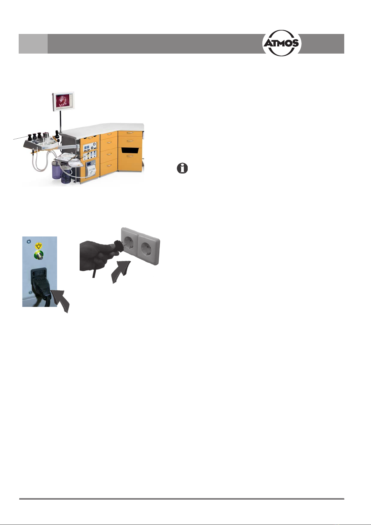
3.1 Front view .............................................................8
3.2 Connection to electrical power line .......................9
4.0 Operation...........................................................10
4.1 ATMOS®S 41 Gyne - Basic device ....................10
4.2 Basic functions....................................................10
4.2.1 Power supply ......................................................10
4.2.2 Maximum loads...................................................10
4.3 Options................................................................11
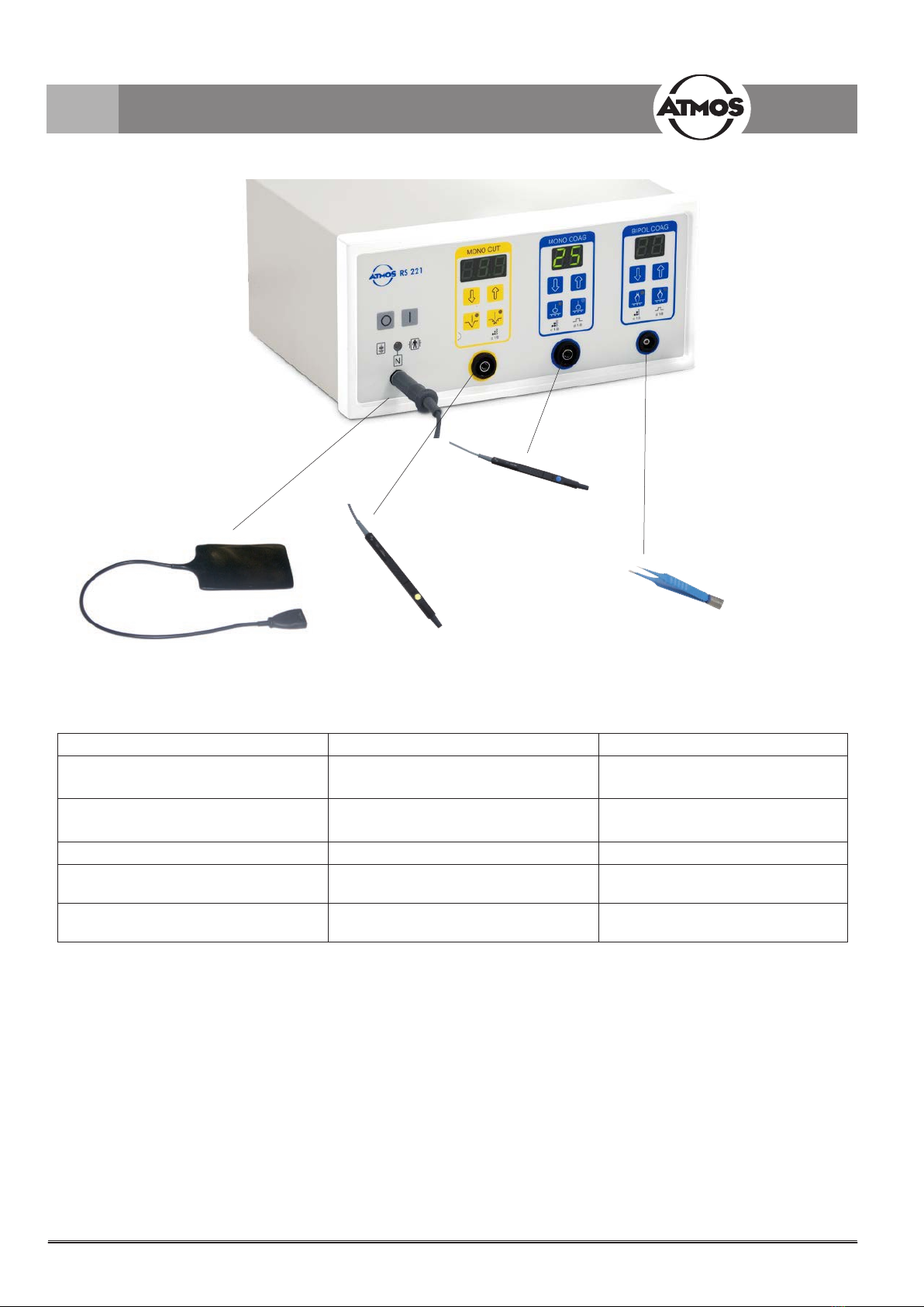
4.3.1 ATMOS®RS 221 (601.1700.0) ...........................11
4.3.2 ATMOS®SE 6501 (601.1900.0)..........................13
4.3.2.1 Operating elements.............................................13
4.3.2.2 Switching on the ATMOS®SE 6501....................13
4.3.2.3 Suction................................................................13
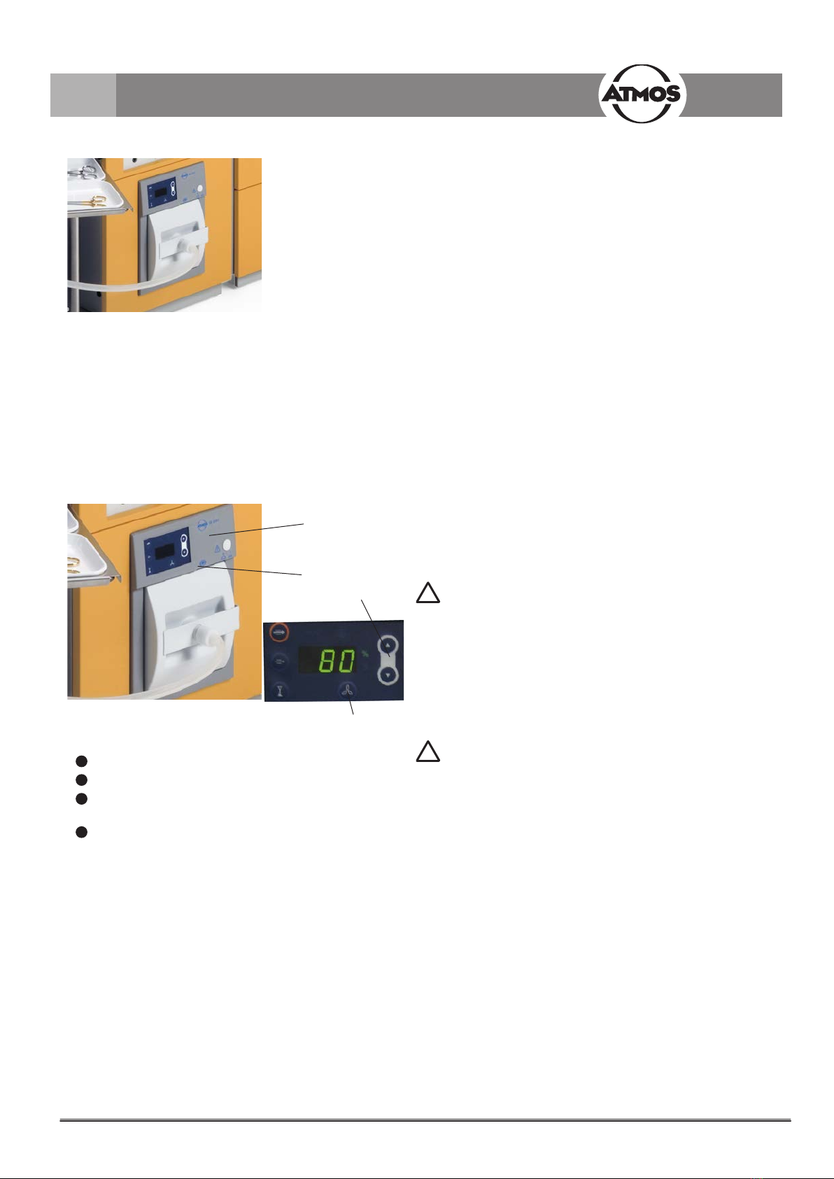
4.3.3 ATMOS®C 401 (601.1500.0)..............................14
4.3.3.1 Operating elements.............................................14
4.3.3.2 On/oswitch .....................................................14
4.3.3.3 Set vacuum.........................................................14
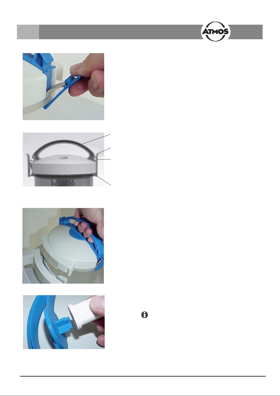
4.3.3.4 Close / open DDS secretion canister handle ......15
4.3.3.5 Attach DDS secretion canister handle ................15
4.3.3.6 Insert / Remove DDS secretion
canister handle....................................................15
4.3.3.7 Insert / Remove bacterial
lter/oversuctionstop........................................15
4.3.3.8 Using the DDS splash protector..........................16
4.3.3.9 Attach DDS secretion canister lid .......................16
4.3.3.10 Remove DDS secretion canister lid ....................16
4.3.3.11 Insert DDS hose adapter ....................................16
4.3.3.12 Connect hose......................................................16
4.3.3.13 Suction................................................................17
4.3.3.14TestDDSbacteriallter/
oversuction stop..................................................17
4.3.4 Video system (ATMOS®Cam 31 DV, TFT display)
(601.1600.0 and 534.3015.0, 534.3010.0) .........17
4.3.4.1 ATMOS®Cam 31 DV ..........................................18
4.3.4.2 Controls and front view .......................................18
4.3.4.3 Camera head ......................................................18
4.3.5 ATMOS®LS 21 LED light source (600.0011.0)...19
4.3.6 Heated drawer ....................................................19
4.3.7 Instrument wet storage (optional) .......................19
4.3.8 Waste bin (optional) ............................................19

3
ATMOS
Phone: + 49 7653 689-0
Fax:
+ 49 7653 689-190
+ 49 7653 689-493 (Service Center)
E-mail: [email protected]
Internet: www.atmosmed.de
MedizinTechnik GmbH & Co. KG
Ludwig-Kegel-Straße 16
79853 Lenzkirch
Germany
1.0 Introduction
1.1 Notes on Operating Instructions
These operating instructions contain important notes on how to operate the ATMOS®S 41 Gyne
safely,correctlyandeectively.Theirreadinghelpstoavoidrisks,andalsotoavoidrepaircostsand
down-times. This increases also the reliability and service-life of your device.
These operating instructions serve not only for new operating personnel to be instructed in its use,
but also for use as a reference manual. Reprints (also in extracts) only with permission in written
form by ATMOS.
These operating instructions must always be kept available near the device.
Care and period tests in conjunction with professional execution provide for operational safety and
readiness for use of your ATMOS®S 41 Gyne and are therefore a must besides regular cleaning.
Repair work and period tests may only be carried out by expert personnel authorised by ATMOS. By
applying only original spare parts you will have the guarantee that operational safety, readiness for
work and the value of your ATMOS®S 41 Gyne will be preserved.
• The unit ATMOS®S 41 Gyne bears CE marking CE 0124 according to the EC Directive of the
council for medical products 93/42/EEC and meets the basic requirements of Appendix I of the
directive.
• The product ATMOS®S 41 Gyne complies with all applicable requirements of the Directive
2011/65/EC restricting the use of certain hazardous substances in electrical and electronic
equipment (“RoHS”).
• The declaration of conformity and our general standard terms and conditions can be obtained on
our website at www.atmosmed.com.
• ThequalitymanagementsystemappliedatATMOShasbeencertiedaccordingtointernational
standards EN ISO 13485.
• Prior to start-up please peruse chapter 2.0 „For your safety“, in order to be prepared for any
possible dangerous situations.
These operating instructions are valid for the following
devices:
ATMOS®S 41 Gyne
Single-tower module ............................REF 602.0000.0
Double-tower module...........................REF 601.0000.0
Three-tower module straight ................REF 603.0000.0
Three-tower module angled .................REF 604.0000.0
Power supply 230 V .............................REF 601.1800.0
Power supply 100 V-127 V...................REF 601.1800.0
Power source ATMOS®LS 21 LED......REF 600.0003.0
ATMOS®C 401 ...................................REF 600.1500.0
Heated drawers
Drawer type A 2....................................REF 601.2300.0
Drawer type B 2 ...................................REF 601.2700.0
The operating instructions are included in the scope of
delivery.

4
1.2 Intended use
1.3 Function
• The ATMOS®S 41 Gyne is started up by connecting the plug to the power supply (page 9).
• To determine the method of functioning of the standard equipment and the optional functions please consult pages 11 to 19,
resp. consult the relevant user manual for the respective device:
- ATMOS®RS 221 (radiofrequency surgery)
- ATMOS®C 401 (suction system)
- ATMOS®Cam 31 (camera)
- ATMOS®LS 21 LED (light source)
1.0 Introduction
Name: ATMOS®S 41 Gyne
Main function: Examinations and therapy in the gynaecological sector
Medical indications /
application:
For application on humans
Specication of the
main function:
• Positioning of instrumentation and accessories
• Illumination and visualization
• Extraction of substances and gas evacuation
• Surgical therapy by means of radio frequency
• Waste collection
Application organ: Female body
Application time: Temporary
Application
site:
In clinics and practices for gynaecologists
Contraindications: • Not for use outside of medical areas
• Not for use in explosion-hazardous areas of medically-used rooms
The product is: active
Sterility: Not necessary
Single-use product /
reprocessing:
Indications for reprocessing are listed in the operating instructions

5
1.4 Explanation of symbols
1.0 Introduction
ON
(for direct electric supply)
according to IEC 417/5007
and DIN 30600/16
Short term operation Type BF equipment
according to IEC 417/5333
OFF
(for direct electric supply)
according to IEC 417/5007
and DIN 30600/16
Foot switch ~Alternating current
Observe operating
instructions!
According to ISO /7000/0434
DIN 30600/1008 IEC 348
Fuse according to IEC
417/5016, DIN 30600/0186 Potential equalisation
Heat output in general;
drawer heating
Type B equipment according
to IEC 417/5333
ATMOS®Cam 31, ATMOS®Cam 31 DV
Fuse according to
IEC 417/5016, DIN
30600/0186
Freeze (Storage) Signal output
Application part type BF Signal input Signal input and output
IEEE
1394 DV port Ground wire connection Foot switch
ATMOS®RS 221
Thedeviceisclassiedas
type:BFanddebrillator
proof.
Neutral electrode, grounded
0124
CE mark in conformity with
93/42 EEC
Device emits non-ionising
radiation HF-radiation
Neutral electrode (shines red
at malfunction)
ATMOS®SE 6501
Thedeviceisclassiedas
type:CFanddebrillator
proof.
DeviceOn/O ECB Used for communication to
optional surgery device
Short cuts / symbols contained in these operating
instructions:
• Indicating a list
- Subdivision of a list/activity
The recommended sequence must be followed in each
case!
!Warning, special diligent notice
Please read, important information

6
• Please note:
A medical insulating transformer with earth leakage
monitor or any similar safety system acc. to EN 60 601-1
is required, if several devices are connected over one
common power supply. The transformer must correspond
to the power consumption of all the devices to be
connected.
• The control panel must be clearly visible and accessible
for the user.
• Theambientconditionsspeciedinthe"Technicaldata"
(chapter 9.0) must be strictly observed!
• The suction system of the ATMOS®S 41 Gyne must
onlybeusedforthesuctionofuidsinthemedicaleld.
Neverremoveexplosive,inammableorcorrosivegases
oruids.
• Switchoallfunctionmoduleswhenyounishyourdaily
business.
• The ATMOS®S 41 Gyne may be operated only in rooms
used for medical purposes, but not in areas subject to
explosion hazards and in oxygen rich environments.
• The ATMOS®S 41 Gyne meets the immunity to
interference requirements of IEC 601-1-2 / EN 60601-
1-2 „Electromagnetic Compatibility – Medical Electrical
Devices“.
• The ATMOS®S 41 Gyne may not be operated with
devices not complying with the requirements of standard
EN 60601-1 „Medical Electrical Equipment“ and EN
60601-1-2 „Electromagnetic Compatibility“ (Medical
Electrical Equipment).
• There are no warranty claims whatsoever on defects
which arise from the use of third party accessories or
consumables.
• ATMOS is not liable for personal injury and damage to
property if
- no original ATMOS parts are being used,
- the advice for use in these operating instructions is
not being observed,
- assembly, new settings, alterations, extensions
and repairs have been carried out by personnel not
authorised by ATMOS.
• Also pay also attention to the safety information in
following chapters.
• The ATMOS®C 401 has been designed in accordance
with IEC 601/ EN 60601. It is assigned to VDE protection
class II. It may only be connected to a properly installed
earthed wall socket.
2.0 For your safety
!
For your safety
• The ATMOS®S 41 Gyne is produced according to IEC
601 / EN 60601 and listed in the following classes:
- Class of protection 1
- Class IIa (EEC 93/42)
- Class IIb (installation of ATMOS®RS 221!)
• The device may only be connected to a properly installed
safety socket.
• The ATMOS®S 41 Gyne is separated from the electricity
network via the rubber connector.
• Caution! Heated drawers may generate temperatures
above 40°C! Check the temperature of the instruments
prior to use. Contact service if necessary!
• The ATMOS®S 41 Gyne may only be used under the
supervisionofskilledstawhohavebeenauthorised
by ATMOS and trained in its operation (IEC 601-1/EN
60601-1).
• The mains voltage indicated on the type plate must
correspond to the values of the supply network.
• Make sure prior to every application of the equipment that
it is technically safe and in proper condition. Damaged
leads and hoses must be replaced immediately!
• Please pay attention to the period tests in chapter 6.0
„Maintenance and service“ on page 25.
• Correctcongurationinassemblyofcountry-specic
connections:
- green/yellow: protective conductor (PE)
- blue: neutral conductor (N)
- black or brown: phase (L)
• Please observe that the mobile parts could cause injury
and contusion!
• If there is a failure in the temperature control then higher
temperatures can occur. Check the temperature of the
instruments prior to use. Contact service if necessary!

7
Notes on EMC
The ATMOS®S 41 Gyne is an examination and treatment
unit designed for use in the gynaecological sector,
combining several single medical products in one system
accordingtoyourindividualconguration.
Each installed device has been tested for EMC.
Following the review of all individual test reports, we can
declarethatasignicantdeteriorationinthestrayradiation
value due to the combination of the devices in the unit is
not to be expected, and what is more, deterioration in the
interference immunity can safely be excluded.
Please observe the instructions relating to EMC in the
relevantunit-specicusermanualwhichisenclosedwith
your supplied unit.
!
For your safety
2.0 For your safety
• Check device, secretion canister, power cable,
accessories, connection cables and hoses for damage
before start-up.
Defect cables and hoses must be replaced immediately.
Check functions of the device prior to using it!
• Do not allow any liquid to get into the device. If liquids
have penetrated the device, it may not be operated again
until it has been checked by the customer service centre.
• Danger of tipping over! If you are transporting a straight
(not angled) workstation with two or three modules
(REF 601.0000.0 / REF 603.0000.0), prior to transport
the drawers must be secured to prevent them from
slipping out.
• After the transport of the device in temperatures below
0°Corpriortorststartupitshouldbekeptatroom
temperature for at least six hours. If the device is not
acclimatized it may not be used as damage to the
diaphragms of the pump could occur.
• The suction hose must never come into direct contact
with the suction area. A suction catheter, suction
attachment or medical suction instruments must always
be used.
• Todisconnectthedevicefromthemainssupply,rst
remove the plug from the wall outlet. Then disconnect the
connection line from the device. Never touch plug or line
with wet hands.
• This product is not re-sterilizable. Repeated reuse of
components which are marked with a 2is forbidden.
In case of repeated reuse these components lose their
function and there is a high infection risk.

8
3.1 Front view
1Swivel-mounted instrument trays (optional)
2ATMOS®Cam 31 module (optional)
3ATMOS®RS 221, radiosurgery device (optional)
4ATMOS®SE 6501 smoke evacuation system (optional)
5ATMOS®C 401 (optional)
6Drawers, heated and unheated (optional)
7Instrument wet storage (optional)
8PC support (optional)
9Glove dispenser (optional)
10 Instrument deposit with cover (optional)
11 Drawer for electrodes (optional)
12 TFT display (optional)
13 Swivel arm with deposit (optional)
14 Connection for foot switch
Castors for mobility (optional) (no illustration available)
3.0 Setting up and starting up
Fig. 1. ATMOS®S 41 Gyne front view
12
13
10
14
11

9
3.2 Connection to electrical power line
• The power cable of the ATMOS®S 41 Gyne is connected
to an earthing contact socket near the unit (max. 3 m).
• The current consumption of the ATMOS®S 41 Gyne
comes to 7 A max.
• Please provide an adequate number of shock-proof plug
terminals to supply the additional electrically operated
unitswhicharenotdenedasoptions,attheworkstation
of the gynaecologist.
Multiple sockets with moveable connection cable may not
be used (please see 2.0 safety notes)!
3.0 Setting up and starting up

10
4.0 Operation
4.2 Basic functions
4.2.1 Power supply
• The ATMOS®S 41 Gyne is separated from the electricity
network via the rubber connector.
4.2.2 Maximum loads
• Persons must not lean on the ATMOS®S 41 Gyne
(danger of tipping over).
• Maximum load of the function carrier: 12 kg.
Fig. 2.
4.1 ATMOS®S 41 Gyne - Basic module
The unique concept of the ATMOS workstation centralises
and integrates all the devices required for diagnosis and
treatmentandthereforeimprovesyourworkow.Basedon
yourndingsalloutpatienttreatmentscanbeperformed
directly and without any long waiting time in one room.
The instrument deposit area:
A storage area for medicine bottles and consumables ()
is located at the head of the function column. There is also
the facility for protective storage of required instruments and
consumables in the drawers ( ).
The unit's surfaces are coated with a special textured
lacquerthatfullstherequirementsforworkplacehygiene.
However, as the lacquer is not resistant to all medicines
and disinfectants it is imperative to wipe up splashes
immediately.
+
Fig. 3.

11
4.3 Options
4.3.1 ATMOS®RS 221 (601.1700.0)
• Please pay attention to the safety and operating notes in
the attached operating manual.
Fig. 4. ATMOS®RS 221
ON I
OFF 0
Symbol for type of device
according to EN 60601
Symbol for neutral electrode
(shines red at malfunction)
Symbol for operating
mode neutral electrode
MONO CUT
Cutting monopolar
Monopolar cutting with
coagulation /
setting of coagulation degree
Output /
coagulation degree lower
Output /
coagulation degree higher
Display output /
coagulation degree
MONO COAG
Permanent coagulation monopolar /
setting of coagulation degree
Pulse coagulation monopolar /
setting of pulse duration
Output / coagulation degree /
pulse duration lower
Output / coagulation degree /
pulse duration higher
Display output /
coagulation degree /
pulse duration
BIPOL COAG
Permanent coagulation bipolar /
setting of coagulation degree
Pulse coagulation bipolar /
setting of pulse duration
Output / coagulation degree /
pulse duration lower
Output / coagulation degree /
pulse duration higher
Display output /
coagulation degree /
pulse duration
Fig. 5.
4.0 Operation

12
Connection
monopolar COAG
Connection monopolar
cut Connection bipolar
COAG
Connection neutral electrode
Fig. 6.
Gynaecology Recommended adjustment Recommended type of electrodes
Conisation on the portio uteri approx. 65 CUT/COAG c3
approx. 40 CUT/COAG c3/c2
BIO-CONE
Loop electrodes
Gynaecomasty approx. 27 CUT Blade electrodes
Multi-Tip
Test excision (vulva) approx. 22 CUT Rhomb electrode
Mamma reduction (see also
subcutaneous fat tissue)
approx. 28-30 CUT; CUT/COAG Needle electrode, Multi-Tip
Mamma augmentation (see also
subcutaneous fat tissue)
approx. 28-30 CUT; CUT/COAG Needle electrode, blade electrode
4.0 Operation

13
4.3.2 ATMOS®SE 6501 (601.1900.0)
• Please pay attention to the safety and operating notes in
the attached operating instructions.
Whenever the electro-surgical device is used, the smoke
evacuation device automatically switches to extraction
operation. ATMOS®SE 6501 returns to basic suction
operation after completion of the incision procedure and the
tracking sequence.
Fig. 7. SE 6501
Automatic activation
With the integrated radiosurgical modules (ATMOS®RS
221) and smoke gas module (ATMOS®SE 6501) the suction
is automatically activated/deactivated during application with
the radiosurgical unit.
Setting operation suction
The terms manual start and manual deactivation mean the
use of the <Start suction> button. Select the button <Value
higher> / <Value lower> a value between 20 and 100% and
conrmwiththeStart/Stopbutton.100%correspondstoa
suction capacity of approx. 650 l/min.
Setting the follow-up time
Theoperationsuctionrunsonforaspeciedlengthoftime
after the ATMOS®SE 6501 is deactivated. This period of
time is the follow-up time. Select a value between 0 and 10
seconds, using the <Higher> / <Lower> (g.8)buttons.
You can also let the operation suction continue running for
anindeniteperiodafterdeactivationoftheelectrosurgical
unit or after manual deactivation of the ATMOS®SE 6501.
Select a period longer than 10 seconds, using the <Higher>
(g.8)button.Theword"On"appearsonthedisplay.The
permanent operation suction mode is activated.
The permanent operation suction can be switched on and
owiththe<Startsuction>button(g.8).
4.3.2.3 Suction
WARNING
Position the suction device, or the instrument with suction
device so that it cannot accidentally suck up swabs or the
like.
Press the <Start suction> button or activate the attached
laser or electro surgical device. The unit operates so long
as the button is pressed or the attached laser or electro
surgical device is activated. Suction then continues for the
duration of the set follow-up time, after which basic suction
takes place for the duration of the set basic suction time.
WARNING!
Never bring the suction hose into contact with the suction
site. It could become attached to the tissue.
ATTENTION:
Do not suck up any liquids. If there is a risk that you could
suckupliquidsduringtheoperation,attachanin-linelter
onthemainlter.Replacethein-linelterimmediatelyifyou
have sucked up any liquid.
For smoke evacuation we recommend the use of the
ATMOS®specula.
!
!
4.3.2.2 Switching on the ATMOS®SE 6501
Switch on the power switch (g.8).TheATMOS®SE
6501 performs a self-test. All the displays illuminate.
Suction performance and run-down time are adjustable.
Select the desired function.
Using the value higher / lower buttons you can change the
value of the selected function (g.8).
You can see the value on the display. The displayed value is
either a percentage or in seconds. The percentage symbol
orsecondssymbolilluminates.Thepercentagegurerefers
to the device's maximum output (650 l/min).
4.3.2.1 Operating elements
Mainson/oswitch
Mainslter
Value higher / value lower button to adjust the value in
the display
Indication of suction capacity
Fig. 8.
4.0 Operation
1
2
3
4

14
4.3.3 ATMOS®C 401 (601.1500.0) suction system
with DDS system (Direct Docking System)
Please pay attention to the safety and operating notes in the
attached operating instructions.
4.3.3.1 Operating elements
On/oswitchwithcontroldisplay
Vacuum gauge
Vacuum control
1
2
3
Fig. 9. ATMOS®C 401
4.3.3.2 On / o switch
• Push the “I” symbol to switch on the device.
• Pushthe“O”symboltoswitchothedevice.
4.3.3.3 Set vacuum
• Close the suction hose and set the desired vacuum by
turning the vacuum controller according to the direction
of the arrow.
Do not use force to turn the knob to its limits!
• Test the system for leaks if the desired vacuum is not
achieved.
!
Fig. 10.
4.0 Operation

15
4.3.3.7 Insert / Remove bacterial lter /
oversuction stop
Usegloves!TheDDSbacteriallterisinsertedintotheDDS
secretion canister handle.
To do this separate the DDS secretion canister handle and
DDSsecretioncanisterlid.PlugtheDDSbacteriallteronto
the cross in the middle of the DDS secretion canister handle
(seeg.14)puttheDDSsecretioncanisterhandleontothe
DDS secretion canister lid.
Fig. 14.
4.3.3.5 Attach DDS secretion canister handle
• Fix the secretion canister handle into the guiding of the
lid with opened snap-in hook .
• Fix the snap-in hook below the canister edge and
press the lever towards the centre of the canister until the
handle snaps in.
Use of the second container
Move the lever in the direction of the container which is not
in use.
Fig. 12.
4.0 Operation
Secretion
canister handle
Lever
Guide
Snap-in hook
4.3.3.4 Close / open DDS secretion canister
handle
• To close, secure the snap-in hooks under the edge of the
secretion canister, and then press the clips downwards
untiltheylockintoplace(seeg.11).
• To open, pull the clips upwards to release the snap-in
hooks and remove from under the edge of the secretion
canister.
Fig. 11.
Fig. 13.
4.3.3.6 Insert / Remove DDS secretion canister
handle
• For removal, lift the DDS secretion canister vertically
upwards; to insert it again, allow it to slide vertically
downwardsintothesecuringdevice(seeg13).

16
Fig. 18.
4.3.3.11 Insert / Remove DDS hose adapter
• Press the required DDS hose adapter with 6 or 10 mm
diameter into the opening on the DDS secretion canister
lidtwistingslightlytoensureatightt(seeg.18).
• Twist slightly in the same manner when removing.
4.3.3.12 Connect hose
• Fixthehosetightlytotheadapter(olive)(seeg.19).
Fig. 19.
4.3.3.8 Using the DDS splash protector
Insert the DDS splash protector into the inner part of the
DDSsecretioncanisterlid(seeg.12).
Fig. 15. 4.3.3.9 Attach DDS secretion canister lid
• WiththeDDSsecretioncanisteronarmsurface,
position the lid horizontally on top. The lid may not be
twisted(seeg.16)!
• Press it tightly with both hands as far as it will go onto the
canister.
Fig. 16. 4.3.3.10 Remove DDS secretion canister lid
With one hand on the canister handle lift the complete
canister upwards. With the other hand on the canister base
guide the canister in order to prevent it from tilting when
liftingitout.Presstheleverapart(seeg.18).
Unhinge the snap-in hook of the canister handle at the
canister. Pull out the snap-in hook with both hands and
remove the canister handle upwards. Remove bacterial
lter/oversuctionstopfromthecanisterhandle.
Remove the canister lid from the canister with both hands.
Remove the splash protection.
Fig. 17.
4.0 Operation

17
4.0 Operation
4.3.3.13 Suction
• Use appropriate suction catheters, suction tips or suction
instruments.
Make sure to disinfect the suction hose, the suction
instruments and the complete secretion canisters prior to
every application on a patient.
Observe the liquid level in the secretion canister during
suction.
• Thehydrophobicbacteriallter/oversuctionstopsafely
prevents liquid from getting into the pump. Nevertheless,
the secretion canister should be replaced when 2/3 full.
4.3.3.14 Test DDS bacterial lter / oversuction
stop
• TheDDSbacteriallter/oversuctionstopisdisposable.
Prior to each use please check whether the DDS bacterial
lter/oversuctionstopisdryandclean.Wetordirtylters
must be replaced with new ones.
Thelterisnolongerinoptimumconditionifthevacuum
displayed is above -0.3 bar when the vacuum controller is in
the”max.”positionandthesuctionhoseisopen.Thelter
must then be replaced.
ReplacetheDDSbacteriallteratleastonceaday.Use
onlyoriginalATMOSbacteriallters!
The device may never be operated without DDS
bacterial lter / oversuction stop!
4.3.4 Video system (ATMOS®Cam 31 DV, TFT
display) (601.1600.0 and 534.3015.0,
534.3010.0)
• Please pay attention to the safety and operating notes in
the attached operating manuals.
• Toallowthepatienttofollowandvisualisethendings
of the endoscopic resp. colposcopic procedures, the
ATMOS®S 41 Gyne can be supplemented optionally by a
video system, consisting of a camera as well as a display
on the arm carrier.
• It is possible to freeze a video image via a foot switch
(camera accessory).
When transferring the video signal to other devices (video
printer, video recorder, computer,...) attention must be paid
to approval as a medical product.
Fig. 20. TFT display and ATMOS®Cam 31 DV

18
4.3.4.1 ATMOS®Cam 31 DV
Please note:
Read the separate operating instructions attentively and follow the stated notes for your safety to guarantee ideal and safe use
of all functions!
!
21
Choose light source
1.) at the treatment unit:
Take out the wanted light source. The adjustments on the unit (LED, Halogen) have been set ex works.
2.) directly at the camera:
Take out the wanted light source (see above). Choose desired optics by pressing the button at the camera ().
Choose the used light source ().
When using the camera next time, all adjustments will be taken over from prior use.
A
B
Connection for camera head
Connection for LED
light source
Buttons for selecting
application part and
light source
Mainson/o
switch
4.3.4.2 Controls and front view
4.3.4.3 Camera head
12
Fig. 21.
4.0 Operation
click

19
4.3.6 Heated drawer
Check the temperature of the instruments prior to use.
If there is a failure in the temperature control then
temperatures exceeding 40 °C could occur. If necessary, call
the service department
Type A 2 (601.2300.0)
Type B 2 (601.2700.0)
maximum load: 10 kg
Mains switch is accessible after pulling out the drawer.
!
4.3.5 ATMOS®LS 21 LED light source
(600.0011.0)
Please pay attention to the safety and operating notes in the
attached operating manual.
Fig. 22. ATMOS®LS 21 LED
click
4.0 Operation
Fig. 23. Heated drawers 4.3.7 Instrument wet storage (optional)
• Includes a removable disinfectant-proof stainless steel
holder with sieve insert and splash protection.
Dimensions: 374 mm x 289 mm x 233 mm
Capacity: 10 litres
Fig. 24.
4.3.8 Waste bin (optional)
• Thedoorofthewastebinisttedwitha"kickbox"
locking device. The waste bin automatically opens a little
by lightly touching the door with the hand or foot.
• The kick box locks automatically on closing.
Caution with contact or exposure to contaminated waste!
Risk of infection!
!

20
5.1 General information on cleaning and
disinfection
Switchalldevicesopriortocleaninganddisinfection!
The described action relating to cleaning and disinfection
resp. sterilisation do not substitute the relevant instructions
which must be adhered to prior to operation!
• For disinfection, you may use all listed surface and
instrument disinfectants.
Alwaysobservetheconcentrationspecicationsand
instructions by the respective manufacturer!
• Do not use
- Disinfectants which contain organic or inorganic acids
or bases as they could cause corrosion damage.
- Disinfectants containing chloramides, phenol
derivatives or anionic tensides, as these may cause
stress cracks in the material used for the housing of
the unit.
5.1.1 Cleaning the unit surface
• The surfaces of the ATMOS®S 41 Gyne are resistant
against all surface disinfectants listed on page 22.
• Wipe the unit surface with a cloth moistened with a
cleaning or disinfecting solution.
• You may also use disinfectant sprays or disinfectant
tissues for cleaning and disinfection.
ªPlease note that the alcohol contained in these
agents could corrode or cloud the protective covers if
employed on a long term basis.
5.1.2 Cleaning "application parts"
"Application parts" comprise:
All parts or components which come into contact with the
patient and could be contaminated:
• Secretion canister,
• Secretion canister lid,
• Hose adapter,
• Secretion hose.
All application parts can be disinfected using the
recommended instrument disinfecting solution (see page
21).
All application parts which are exposed to direct contact with
the patient during treatment must be exchanged or cleaned
and disinfected immediately for hygienic reasons.
!
5.1.3 Secretion canister, bacterial lter and
suction hose
At the end of every working-day, following parts must be
cleaned and disinfected:
• Secretioncanisterwithlidsystemandbacteriallter:
- Detach all hose connections carefully on the lid
system and take secretion canister out carefully to
prevent spills and contamination of the area. Dispose
of secretions properly.
- Griplidsystemrmly,openlidoflterhousingby
turninginanti-clockwisedirectionandremovelter.
Rinse all parts thoroughly under running water. A
detergent or cleaning agent may also be used if
required.
- Disinfection with disinfectants recommended in
chapter 5.3 for surface disinfection.
- Aftercleaningtheltermustbeinserted(smoothside
down).
- Max. cycles of reprocessing:
DDS secretion canister system, silicone hose: 60
cycles
• Suction system and hose attachment:
- After every use, rinse out the suction system by
drawinginasmallamountofrinsinguid(e.g.
ATMOS®special cleanser for suction systems
080.0006.0, dosage: 10 ml to 1 l water).
ªKeeps the suction hoses from becoming sticky or
clogged.
- Immersing the hose into disinfection solution.
- Replacethelter.
- Caution with contact or exposure to contaminated
waste! Risk of infection!
5.1.4 Instrument trays
• Before disinfection, thoroughly rinse the trays under
running water. A detergent or cleaning agent may also be
used if required.
- Use water to thoroughly rinse all residues of these
substances.
- Disinfection of the trays with disinfectants
recommended in chapter 5.3 Surface disinfection.
• Stainless steel trays and trays made of anodized
aluminium can be cleaned automatically (Neodisher
MediClean forte). They can also be disinfected thermally
at a temperature of 93°C.
Trays made of melamine do not resist temperatures of
93°C.
!
!
!
5.0 Cleaning and care
Table of contents
Other Atmos Medical Equipment manuals

Atmos
Atmos Twin Record 55 User manual

Atmos
Atmos Variotherm plus User manual

Atmos
Atmos S 042 NPWT User manual

Atmos
Atmos C 31 User manual

Atmos
Atmos S 351 NATAL User manual

Atmos
Atmos C 051 Thorax User manual

Atmos
Atmos A 161 Battery Series User manual

Atmos
Atmos Scope User manual

Atmos
Atmos E 1 User manual

Atmos
Atmos S 351 OT User manual

Atmos
Atmos Chair 21 P User manual

Atmos
Atmos E 201 Thorax User manual

Atmos
Atmos Scope User manual

Atmos
Atmos LC 27 User manual

Atmos
Atmos S 201 Thorax User manual

Atmos
Atmos S 351 NATAL User manual

Atmos
Atmos ENT User manual

Atmos
Atmos S 201 Thorax User manual

Atmos
Atmos C 451 User manual

Atmos
Atmos S 201 Thorax User manual