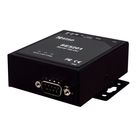
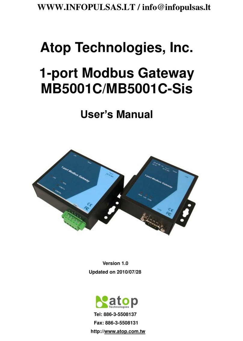
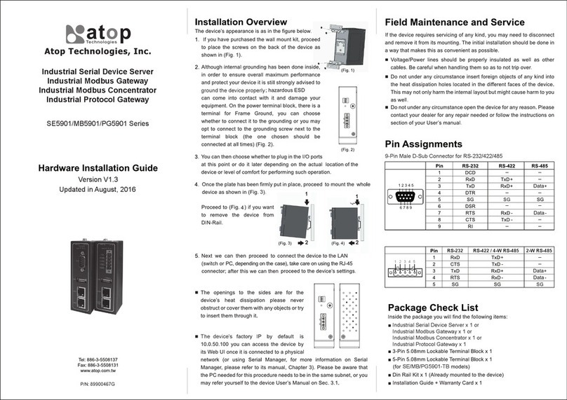
Atop CR5201B Series User manual

CR5201B/SE5201B
User Manual
v1.0
1
CR5201B/SE5201B Series
Low-Power Wide-Area NB-IoT/Cat. M1/LTE Cat.1 Gateway
User Manual
v1.0
April 14th, 2023
Atop Technologies, Inc.

CR5201B/SE5201B
User Manual
v1.0
2
This PDF Document contains internal hyperlinks for ease of navigation.
For example, click on any item listed in the Table of Contents to go to that page.
Published by:
Atop Technologies, Inc.
2F, No. 146, Sec. 1, Tung-Hsing Rd,
30261 Chupei City,
Hsinchu County
Taiwan, R.O.C.
Tel: +886-3-550-8137
Fax: +886-3-550-8131
sales@atop.com.tw
www.atoponline.com
www.atop.com.tw

CR5201B/SE5201B
User Manual
v1.0
3
Important Announcement
The information contained in this document is the property of Atop technologies, Inc., and is supplied for the sole
purpose of operation and maintenance of Atop Technologies, Inc., products.
No part of this publication is to be used for any other purposes, and it is not to be reproduced, copied, disclosed,
transmitted, stored in a retrieval system, or translated into any human or computer language, in any form, by any
means, in whole or in part, without the prior explicit written consent of Atop Technologies, Inc.,
Offenders will be held liable for damages and prosecution.
All rights, including rights created by patent grant or registration of a utility model or design, are reserved.
Disclaimer
We have checked the contents of this manual for agreement with the hardware and the software described. Since
deviations cannot be precluded entirely, we cannot guarantee full agreement. However, the data in this manual is
reviewed regularly and any necessary corrections will be included in subsequent editions.
Suggestions for improvement are welcome.
All other product’s names referenced herein are registered trademarks of their respective companies.
Documentation Control
Author:
Sean Hong
Revision:
1.0
Revision History:
First Release
Creation Date:
13 April 2023
Last Revision Date:
13 April 2023
Product Reference:
Low-Power Wide-Area NB-IoT/Cat. M1/LTE Cat.1 Gateway User
Manual
Document Status:
First Release

CR5201B/SE5201B
User Manual
v1.0
4
Table of Contents
1Preface .................................................................................................................................9
1.1 Purpose of the Manual...........................................................................................................................9
1.2 Who Should Use This User Manual .......................................................................................................9
1.3 Supported Platform ................................................................................................................................9
1.4 Manufacturers’ FCC Declaration of Conformity Statement .................................................................9
2Introduction....................................................................................................................... 10
2.1 Overview............................................................................................................................................... 10
2.2 Features ............................................................................................................................................... 11
3Getting Started.................................................................................................................. 12
3.1 Packing List ......................................................................................................................................... 12
3.2 Appearance, Front and Rear Panels ................................................................................................... 13
3.3 First Time Installation ......................................................................................................................... 14
3.4 Factory Default Settings...................................................................................................................... 15
3.4.1 Network Default Settings .................................................................................................................... 15
3.4.2 Other Default Settings......................................................................................................................... 15
4Configuration and Setup .................................................................................................. 16
4.1 Configuration of Network Parameters through Device Management Utility ................................... 16
4.2 Configuring through Web/CLI Interface............................................................................................. 19
4.3 Configuring Automatic IP Assignment with DHCP ........................................................................... 21
4.4 Web Overview ...................................................................................................................................... 21
4.5 Network Settings ................................................................................................................................. 22
4.5.1 IPv4 Settings........................................................................................................................................ 23
4.5.2 4G Settings (Cellular Settings) ........................................................................................................... 25
4.5.3 SIM Switch ........................................................................................................................................... 26
4.6 Firewall Setting .................................................................................................................................... 28
4.6.1 Port Forwarding ................................................................................................................................... 29
4.6.2 DDoS..................................................................................................................................................... 31
4.7 Serial .................................................................................................................................................... 31
4.7.1 COM Port Overview ............................................................................................................................. 32
4.7.2 COM Configuration.............................................................................................................................. 33
4.7.3 COM Configuration: Advanced Settings............................................................................................. 34
4.8 SNMP/ALERT Settings........................................................................................................................ 36
4.9 E-Mail Settings..................................................................................................................................... 37
4.10 GPS....................................................................................................................................................... 39
4.11 VPN ...................................................................................................................................................... 39
4.11.1IPsec..................................................................................................................................................... 40
4.11.2IPsec Settings...................................................................................................................................... 44
4.11.3IPsec Status......................................................................................................................................... 48
4.11.4Examples of IPsec Settings ................................................................................................................ 48
4.11.5Host-to-Host Connections .................................................................................................................. 48
4.11.6Host-to-Network Connections ............................................................................................................ 49
4.11.7Network-to-Network (Subnet-to-Subnet) Connections ..................................................................... 51
4.11.8OpenVPN Setting................................................................................................................................. 52
4.11.9OpenVPN Keys..................................................................................................................................... 54
4.11.10 OpenVPN Status ......................................................................................................................... 55
4.12 Log Settings......................................................................................................................................... 56
4.12.1System Log Settings ........................................................................................................................... 56
4.12.2COM Log Settings................................................................................................................................ 57

CR5201B/SE5201B
User Manual
v1.0
5
4.12.3System Log .......................................................................................................................................... 58
4.12.4COM log ............................................................................................................................................... 59
4.12.5Mobile Log ........................................................................................................................................... 59
4.13 System Setup....................................................................................................................................... 61
4.13.1Date/Time Settings ............................................................................................................................. 61
4.13.2Admin Settings .................................................................................................................................... 62
4.13.3Firmware Upgrade ............................................................................................................................... 63
4.13.4Backup/Restore Configuration ........................................................................................................... 64
4.13.5Power Management ............................................................................................................................ 66
4.13.6Ping ...................................................................................................................................................... 70
4.14 Reboot.................................................................................................................................................. 71
4.14.1Auto Reboot ......................................................................................................................................... 71
4.14.2Manual Reboot .................................................................................................................................... 71
5Link Modes and Applications .......................................................................................... 72
5.1 Link Mode Configuration..................................................................................................................... 72
5.1.1 Link Mode: Configure SE5201B as a TCP Server .............................................................................. 72
5.1.2 Link Mode: Configure SE5201B as a TCP Client................................................................................ 74
5.1.3 Link Mode: Configure SE5201B in UDP.............................................................................................. 76
5.2 Link Mode Applications....................................................................................................................... 78
5.2.1 TCP Server Application: Enable Virtual COM ..................................................................................... 78
5.2.2 TCP Server Application: Enable RFC 2217 through Virtual COM...................................................... 79
5.2.3 TCP Client Application: Enable Virtual COM...................................................................................... 79
5.2.4 TCP Client Application: Enable RFC 2217 through Virtual COM....................................................... 80
5.2.5 TCP Server Application: Configure SE5201B as a Pair Connection Master .................................... 80
5.2.6 TCP Client Application: Configure SE5201B as a Pair Connection Slave ........................................ 80
5.2.7 TCP Server Application: Enable Reverse Telnet................................................................................. 81
6VCOM Installation & Troubleshooting ............................................................................ 83
6.1 Enabling VCOM.................................................................................................................................... 83
6.1.1 VCOM driver setup .............................................................................................................................. 85
6.1.2 Limitation ............................................................................................................................................. 86
6.1.3 Installation ........................................................................................................................................... 86
6.1.4 Uninstallation....................................................................................................................................... 86
6.2 Enable VCOM in Serial Device servers and Select VCOM in Windows ............................................ 86
6.2.1 Enable VCOM in Serial Device servers ............................................................................................... 86
6.2.2 Running Serial/IP Software Utility in Windows................................................................................... 86
6.2.3 Configuring VCOM Ports..................................................................................................................... 89
6.3 Exceptions ........................................................................................................................................... 92
6.4 Using Serial/IP Port Monitor ............................................................................................................... 96
6.4.1 Opening the Port Monitor.................................................................................................................... 96
6.4.2 The Activity Panel................................................................................................................................ 96
6.4.3 The Trace Panel................................................................................................................................... 97
6.5 Serial/IP Advanced Settings ............................................................................................................... 98
6.5.1 Advanced Setting Options .................................................................................................................. 98
6.5.2 Using Serial/IP with a Proxy Server .................................................................................................... 99
7Specifications ................................................................................................................. 100
7.1 Hardware............................................................................................................................................ 100
7.2 Serial port Pin Assignments ............................................................................................................. 101
7.2.1 CR5201B/SE5201B Pin Assignments for Serial Interfaces ............................................................ 101
7.2.2 CR5201B/SE5201B Pin Assignments for Terminal Block .............................................................. 102
7.3 LED Indicators ................................................................................................................................... 103
7.4 Software............................................................................................................................................. 103
8Warranty .......................................................................................................................... 104

CR5201B/SE5201B
User Manual
v1.0
6
Table of Figures
Figure 2.1 An Application of SE5201B with Multiple Charging Piles .......................................................................... 10
Figure 4.1 List of Device in Device Management Utility............................................................................................... 16
Figure 4.2 Pull-down Menu of Configuration and Network... ...................................................................................... 17
Figure 4.3 Pop-up Window of Network Setting ............................................................................................................ 17
Figure 4.4 Authorization for Change of Network Settings........................................................................................... 18
Figure 4.5 Pop-up Notification Window after Authorization ....................................................................................... 18
Figure 4.6 Pop-up Notification Window when there is the same IP address in the network..................................... 18
Figure 4.7 Require Authentication for Accessing Web Interface ................................................................................ 19
Figure 4.8 Overview Webpage of SE5201B Low-Power Gateway ............................................................................... 19
Figure 4.9 Memu of Configuring Web Page on SE5201B Low-Power Gateway......................................................... 20
Figure 4.10 Access control............................................................................................................................................ 20
Figure 4.11 CLI interface................................................................................................................................................ 21
Figure 4.12 Selecting DHCP Option .............................................................................................................................. 21
Figure 4.13 Enable DHCP Option................................................................................................................................... 21
Figure 4.14 Overview Web Page (example on SE5201B-E) ......................................................................................... 22
Figure 4.15 Three Submenus of the Network Settings Menu...................................................................................... 22
Figure 4.16 IPv4 Setting within the Network Settings Menu ....................................................................................... 23
Figure 4.17 NAT Settings under IPv4 Settings Web Page for SE5201B ..................................................................... 24
Figure 4.18 Enabling of NAT Settings with Additional Parameters for CR5201B/SE5201B ..................................... 24
Figure 4.19 A pop-up window shows an empty list of DHCP Connected Clients....................................................... 25
Figure 4.20 4G Settings Web Page................................................................................................................................ 25
Figure 4.21 SIM Switch Settings Web Page ................................................................................................................. 27
Figure 4.22 Firewall Setting Menu on CR5201B/SE5201B .......................................................................................... 28
Figure 4.23 Example of Port Forwarding through SE5201B Low-Power Gateway..................................................... 29
Figure 4.24 Port Forwarding Web Page of CR5201B/SE5201B series ....................................................................... 30
Figure 4.25 DDoS Settings Web Page ........................................................................................................................... 31
Figure 4.26 Serial Menu (Example on SE5201B).......................................................................................................... 31
Figure 4.27 COM 1 Port Settings Web Page................................................................................................................. 32
Figure 4.28 Serial Setting Part of COM 1 Port .............................................................................................................. 33
Figure 4.29 COM 1 Advanced Settings Web Page ....................................................................................................... 34
Figure 4.30 SNMP/Alert Settings Web Page ................................................................................................................ 36
Figure 4.31 E-mail Setting Web Page............................................................................................................................ 38
Figure 4.32 GPS Web Page............................................................................................................................................ 39
Figure 4.33 VPN Scenario of CR5201B/SE5201B Series............................................................................................. 39
Figure 4.34 VPN Menu Structure................................................................................................................................... 40
Figure 4.35 An Example of Host-to-Host Connection .................................................................................................. 41
Figure 4.36 Roadwarrior Application using Host-to-Subnet Connection .................................................................... 41
Figure 4.37 Gateway Application using Host-to-Subnet Connection .......................................................................... 41
Figure 4.38 An example of network application using a subnet-to-subnet connection via the CR5201B/SE5201B
and a peer device ........................................................................................................................................................... 42
Figure 4.39 An example of host-network application via the subnet-to-subnet connection ..................................... 42
Figure 4.40 An example of host-host application via the subnet-to-subnet connection ........................................... 42
Figure 4.41 IPsec Tunnels Web Page under IPsec Setting Menu ............................................................................... 44
Figure 4.42 IPsec Status Web Page .............................................................................................................................. 48
Figure 4.43 IPsec VPN Tunnel with Host-to-Host Topology........................................................................................ 48
Figure 4.44 General Settings for Host-to-Host with Static Peer.................................................................................. 49
Figure 4.45 General Settings for Host-to-Host with Dynamic Peer............................................................................. 49
Figure 4.46 IPsec VPN Tunnel with Host-to-Network Topology ................................................................................. 50
Figure 4.47 General Settings for Host-to-Network with Static Peer............................................................................ 50
Figure 4.48 General Settings for Host-to-Network with Dynamic Peer....................................................................... 51
Figure 4.49 IPsec VPN Tunnel with Network-to-Network Topology ........................................................................... 51
Figure 4.50 General Settings for Network-to-Network with Static Peer...................................................................... 52
Figure 4.51 General Settings for Network-to-Network with Dynamic Peer................................................................. 52
Figure 4.52 OpenVPN Setting........................................................................................................................................ 53
Figure 4.53 OpenVPN Keys web page .......................................................................................................................... 54

CR5201B/SE5201B
User Manual
v1.0
7
Figure 4.54 Certificate Upload for OpenVPN Server .................................................................................................... 54
Figure 4.55 Certificate Upload for OpenVPN Client ..................................................................................................... 55
Figure 4.56 OpenVPN Client Status .............................................................................................................................. 55
Figure 4.57 OpenVPN Server Status ............................................................................................................................. 56
Figure 4.58 Log Setting Menu ....................................................................................................................................... 56
Figure 4.59 Log Settings Web Page under Log Settings ............................................................................................. 57
Figure 4.60 COM Log Settings Web Page under System Setup .................................................................................. 57
Figure 4.61 System Log Web Page under System Setup............................................................................................. 59
Figure 4.62 COM Datalog Web Page under Log Settings ............................................................................................ 59
Figure 4.63 Mobile Log: Mobile Signal.......................................................................................................................... 60
Figure 4.64 Mobile Log: Mobile Temperature .............................................................................................................. 60
Figure 4.65 System Setup Menu ................................................................................................................................... 61
Figure 4.66 Date/Time Settings Web Page under System Setup................................................................................ 62
Figure 4.67 Admin Settings Web Page under System Setup....................................................................................... 63
Figure 4.68 Firmware Upgrade Web Page under System Setup ................................................................................. 64
Figure 4.69 Backup/Restore Settings Web Page under System Setup....................................................................... 65
Figure 4.70 Power Management Web Page ................................................................................................................. 66
Figure 4.71 Options for Schedule Power Management Mode .................................................................................... 67
Figure 4.72 Example of Connecting a Switch Breaker between DI and DIc Pins on the SE5201B............................ 68
Figure 4.73 Example of LED status while device is in the Hibernate mode ............................................................... 68
Figure 4.74 Example of Device in Wake Up State. ....................................................................................................... 68
Figure 4.75 Location of the Hibernate button on the side of the chasis .................................................................... 69
Figure 4.76 Example of LED status while device is in the Hibernate mode ............................................................... 69
Figure 4.77 Example of Device in Wake Up State ........................................................................................................ 69
Figure 4.78 Ping Web Page under System Setup......................................................................................................... 70
Figure 4.79 Unreachable Ping Example ........................................................................................................................ 70
Figure 4.80 Reboot Web Page with Specific Time Policy ............................................................................................ 71
Figure 4.81 Reboot Web Page with Period Time Policy............................................................................................... 71
Figure 5.1 Link Mode Options for COM1 Port .............................................................................................................. 72
Figure 5.2 CR5201B/SE5201B is set as a TCP Server Link Mode............................................................................... 72
Figure 5.3 Connection Settings for TCP Server Link Mode ........................................................................................ 73
Figure 5.4 TCP Server Link Mode Settings under COM 1 Page................................................................................... 73
Figure 5.5 Example of SE5201B Configured as TCP Client Link Mode ...................................................................... 74
Figure 5.6 Connection Settings for TCP Client Link Mode........................................................................................... 75
Figure 5.7 Setting in TCP Client Link Mode .................................................................................................................. 75
Figure 5.8 Example of CR5201B/SE5201B Configured in UDP Link Mode................................................................. 76
Figure 5.9 Connection Setting in UDP Link Mode ........................................................................................................ 77
Figure 5.10 UDP Link Mode Setting under COM 1 Page .............................................................................................. 77
Figure 5.11 Virtual COM Application in TCP Server Link Mode................................................................................... 78
Figure 5.12 Virtual COM Application in TCP Client Link Mode .................................................................................... 79
Figure 5.13 Pair Connection Master Application in TCP Server Link Mode ............................................................... 80
Figure 5.14 Pair Connection Slave Application in TCP Client Link Mode ................................................................... 81
Figure 5.15 Reverse Telnet Application in TCP Server Link Mode .............................................................................. 82
Figure 6.1 Enable a Virtual COM Application When Setting the Link Mode as the TCP Server ................................. 83
Figure 6.2 Enable a Virtual COM Application When Setting the Link Mode as the TCP Client .................................. 84
Figure 6.3 An Example Diagram of Virtual COM Application over TCP/IP Network ................................................... 85
Figure 6.4 Enable Virtual COM Application for COM 1 in TCP Server Link Mode....................................................... 86
Figure 6.5 Serial/IP Tray Icon on Windows Notification Area ..................................................................................... 87
Figure 6.6 A Pop-up Window for Selecting Virtual COM Ports..................................................................................... 88
Figure 6.7 Serial/IP Control Panel Window................................................................................................................... 89
Figure 6.8 Available Options for Use Credential From in Serial/IP Control Panel Version 4.9.10 ............................. 90
Figure 6.9 Configuring Virtual COM 2 Port as TCP Client ............................................................................................ 91
Figure 6.10 Auto Configure (formerly Configuration Wizard) Window for COM 1 ..................................................... 91
Figure 6.11 Timeout Warning on VCOM Connection ................................................................................................... 92
Figure 6.12 Error of Client not licensed for this server................................................................................................. 93
Figure 6.13 Licensing Issue of Serial/IP Utility Software ............................................................................................. 93
Figure 6.14 VCOM Authentication failed due to Missing Username/Password ........................................................ 94
CR5201B/SE5201B
User Manual
v1.0
8
Figure 6.15 VCOM Authentication failed due to incorrect Username and/or Password ............................................ 94
Figure 6.16 VCOM Authentication failed due to disabled VCOM Authentication on SE5201B ................................. 95
Figure 6.17 Activity Panel of Serial/IP Port Monitor..................................................................................................... 96
Figure 6.18 Trace Panel of Serial/IP Port Monitor ........................................................................................................ 97
Figure 6.19 Serial/IP Advanced Settings Window ........................................................................................................ 98
Figure 6.20 Proxy Server Tab under Serial/IP Advanced Settings .............................................................................. 99
Figure 7.1 DB9 Pin Number ......................................................................................................................................... 101
Figure 7.2 TB5 Pin Number.......................................................................................................................................... 101
Figure 7.3 3-pin 3.81mm lockable Terminal Block..................................................................................................... 102
Figure 7.4 SE5201B Pin Assignments for Terminal Block........................................................................................ 102
List of Tables
Table 3.1 Packing List.................................................................................................................................................... 12
Table 3.2 Description of Optional Accessories ............................................................................................................ 12
Table 3.3 Network Default Settings .............................................................................................................................. 15
Table 3.4 Security, Serial, and SNMP Default Settings ................................................................................................ 15
Table 4.1 Descriptions of 4G Settings .......................................................................................................................... 26
Table 4.2 Description of SIM Switch’s parameters ...................................................................................................... 28
Table 4.3 Description of Fields in Port Forwarding Table............................................................................................ 30
Table 4.4 Description of Parameters in IPsec Tunnels Web Page.............................................................................. 46
Table 4.5 Description of Power Management Settings ............................................................................................... 67
Table 7.1 Hardware Specification ............................................................................................................................... 100
Table 7.2 CR5201B/SE5201B Pin Assignment for DB9 to RS-232 /RS-485 Connector........................................... 101
Table 7.3 CR5201B/SE5201B Pin Assignment for TB5 to RS-232/ RS-485 Connector........................................... 101
Table 7.4 CR5201B Pin Assignments for Terminal Block ......................................................................................... 102
Table 7.5 SE5201B Power Connector& DIO............................................................................................................... 102

CR5201B/SE5201B
User Manual
v1.0
9
1Preface
1.1 Purpose of the Manual
This manual supports user during the installation and configuring of the CR5201B/SE5201B Industrial Device Server
Series. It explains the technical features available with the product. For example, it contains some advanced
network management knowledge, instructions, examples, guidelines, and general theories to assist user’s device
management in both hardware and software. A background in general theory is necessary when reading it. Please
refer to the Glossary for technical terms and abbreviations (if any).
1.2 Who Should Use This User Manual
This manual is to be used by any qualified network personnel or support technicians who are familiar with network
operations.It might be useful for system programmers or network planners as well. This manual also provides
helpful and handy information for the first-time users. For any problems on this manual, please contact your local
distributor. If they are unable to assist you, please redirect your inquiries to www.atop.com.tw or
www.atoponline.com.
1.3 Supported Platform
This manual is designed for CR5201B/SE5201B Low-Power Gateway only.
1.4 Manufacturers’ FCC Declaration of Conformity Statement
NOTE: This equipment has been tested and found to comply with the limits for a Class A digital device, pursuant to
Part 15 of the FCC rules. These limits are designed to provide reasonable protection against harmful interference
when the equipment is operated in a commercial environment. This equipment generates, uses, and can radiate
radio frequency energy and, if not installed and used in accordance with the instruction manual, may cause harmful
interference to radio communications. Operation of this equipment in a residential area is likely to cause harmful
interference in which case the user will be required to correct the interference at his/her own expense.
This device complies with Part 15 of the FCC Rules.
Operation is subject to the following two conditions:
1. This device may not cause harmful interference, and
2. This device must accept any interference received, including interference that may cause an undesired
operation.
Note: all the figures herein are intended for illustration purposes only. This software and certain features work
only on certain Atop’s devices.

CR5201B/SE5201B
User Manual
v1.0
10
2Introduction
2.1 Overview
The CR5201B/SE5201B is a Low-Power Wide-Area NB-IoT/Cat. M1/LTE Cat.1 Gateway, which acts as a gateway
for communications between Ethernet (TCP/UDP) port, and SE5201B also has built-in RS-232/ RS-485 port.
The information conveyed by the SE5201B model is transparent to both host computers (Ethernet) and serial
devices (RS-232/ RS-485). Data coming from the Ethernet port is sent to the designated RS-232/ RS-485 port, and
data received from RS-232/ RS-485 port is sent to the Ethernet port, allowing full-duplex and bi-directional
communication. In the computer-aided manufacturing or industrial automation areas, field devices can directly
connect to an Ethernet network via the SE5201B model. In normal PCs or laptops, a virtual COM port can be created
using our virtual COM software to fetch serial data from SE5201B remotely over Ethernet. Note that SE5201B model
does not support RS-422 and 4-wired RS-485. With the SE5201B model, it is possible to communicate with a remote
serial device over the LAN or even over the Internet, which dramatically increases reachability and scalability.
Figure 2.1 illustrates an example of multiple charging piles connected to the SE5201B.
The SE5201B can simplify the process of transforming legacy lighting systems into electric car charging piles.
Serval Charging piles connect to the SE5201B via Ethernet interface, and a monitored device reports to SE5201B
via RS-232/ RS-485 interface. The SE5201B provides low-power, reliable, and secure connectivity so that the device
data can be sent to the control center for remote monitoring and control.
Figure 2.1 An Application of SE5201B with Multiple Charging Piles
Charging pile
Charging pile
Charging pile
Charging pile
Charging pile
Charging pile
Data Reporting
Data Reporting
Base Station
Control Center

CR5201B/SE5201B
User Manual
v1.0
11
2.2 Features
The CR5201B/SE5201B Low-Power Gateway share the same software platform on different available hardwares.
It provides
•Flexible hardware platform, in different port variants based on your needs
•TCP Server/Client, UDP, Virtual COM and Tunneling modes supported
•Remotely monitor, manage, and control industrial field devices
•Configuration via Web Browser/Serial Console/Telnet Console/Atop’s Windows Utility (Device
Management Utility)
•Rugged metal housing with IP30 protection for wall or DIN-Rail mount
•Wide range power supply input between 9 - 48 VDC
Caution
Beginning from here, extreme caution must be exercised.
Never install or work with electricity or cabling during periods of lightning
activity. Never connect or disconnect power when hazardous gases are
present.
Warning: HOT!
WARNING: Disconnect the power and allow unit to cool for 5 minutes before touching.

CR5201B/SE5201B
User Manual
v1.0
12
3Getting Started
3.1 Packing List
Inside the purchased package, you will find the device and following items.
Table 3.1 Packing List
Item
Part Number
SE5201B-DB
SE5201B-TB
CR5201B-TB
Terminal Block (7P)
50707741G
1
1
N/A
Terminal Block (5P)
50706091G
N/A
1
N/A
Terminal Block (3P)
50706701G
N/A
N/A
1
3G/4G Antenna
59908151G
2
2
2
Hardware Installation Guide (Warranty card
is included)
89900648G
1
1
1
Note:
•Noify your sales representative immediately if any of the above items is missing or damaged upon delivery.
•Atop’s utility software Device View© , Serial Manager© , and Device Management Utility® are obsolete and
replaced by Network Management Utility® .
Table 3.2 Description of Optional Accessories
Optional Accessories
Model Name
Part Number
Description
UN315-1212 US-Y
50500151120003G
Y-Type power adapter, 100~240VAC input, 1.25A @ 12VDC
output, US plug, LV6
UNE315-1212 EU-Y
50500151120013G
Y-Type power adapter, 100~240VAC input, 1.25A @ 12VDC
output, EU plug, LV6
ADP-DB9(F)-TB5
59906231G
Female DB9 to Female 3.81mm TB5 Converter
WMK-315-Black
70100000000050G
Black Aluminum Wall Mount Kit

CR5201B/SE5201B
User Manual
v1.0
13
3.2 Appearance, Front and Rear Panels
The following figures show CR5201B/SE5201B series device’s front and rear panels.
CR5201B
Top
Front
Back
Side
SE5201B
Top
Front (TB5)
Front (DB9)
Back
Side

CR5201B/SE5201B
User Manual
v1.0
14
3.3 First Time Installation
Before installing the device, please follow strictly all safety procedures described in the hardware installation guide
supplied inside the product. Atop will not be liable for any damages to property or personal injuries resulting from
the installation or overall use of the device. Do not attempt to manipulate the product in any way if unsure of the
steps described here. In such cases, please contact your dealer immediately.
Note that some specific installation instructions are not provided here in this manual since they may differ
considerably based on the purchased hardware.

CR5201B/SE5201B
User Manual
v1.0
15
3.4 Factory Default Settings
3.4.1 Network Default Settings
The CR5201B/SE5201B Low-Power Gateway is equipped with two LAN interfaces with one default IP address. Its
default network parameters are listed in Table 3.3.
Table 3.3 Network Default Settings
Interface
Device IP
Subnet Mask
Gateway IP
DNS
LAN1
192.168.1.1
255.255.255.0
192.168.1.254
-
3.4.2 Other Default Settings
The CR5201B/SE5201B comes with the following default settings.
Table 3.4 Security, Serial, and SNMP Default Settings
Parameter
Default Values
Security
User Name
admin
Password
default
Serial
COM1
RS-232, 9600 bps, 8 data bits, No Parity bit,1 stop bit, No Flow Control
No Packet Delimiter timer
SNMP
SysName of SNMP
System
SysLocation of SNMP
Location
SysContact of SNMP
Contact
SNMP
Disabled
Read Community
public
Write Community
private
SNMP Trap Server
0.0.0.0
Note: Press the “Reset” button on the front panel for 5 seconds, to restore the CR5201B/SE5201B Series Low-
Power Gateway to the factory default settings.

CR5201B/SE5201B
User Manual
v1.0
16
4Configuration and Setup
It is strongly recommended for the user to first set network parameters through Device Management Utility© first.
Other device-specific configurations can later be carried out via Atop’s user-friendly Web-Interface.
4.1 Configuration of Network Parameters through Device Management Utility
Please install Atop’s configuration utility program called Device Management Utility® that comes with the Product
CD or can be downloaded from our websites (www.atop.com.tw or www.atoponline.com). For more information
on how to install Device Management Utility® , please refer to the manual that comes in the Product CD. After you
start Device Management Utility® , if the CR5201B/SE5201B Low-Power Gateway is already connected to the same
subnet as your PC, the device can be accessed via broadcast packets. Device Management Utility® will
automatically detect your CR5201B/SE5201B device and list it on Device Management Utility® ’s window.
Alternatively, if you did not see your CR5201B/SE5201B device on your network, press “Rescan” icon, a list of
devices, including your CR5201B/SE5201B device currently connected to the network will be shown in the window
of Device Management Utility® as shown in Figure 4.1.
Figure 4.1 List of Device in Device Management Utility
Note:This figure is for illustration purpose only. Actual values/settings may vary between devices.
Sometime the CR5201B/SE5201B device might not be in the same subnet as your PC; therefore, you will have to
use Atop's utility to locate it in your virtual environment. To configure each device, first click to select the desired
CR5201B/SE5201B device (default IP: 10.0.50.100) in the list of Device Management Utility© , and then click
“Configuration →Network…”(or Ctrl+N) menu on Device Management Utility© as shown in Figure 4.2 or click on
the second icon called Network on the menu icon bar, and a pop-up window will appear as shown in Figure 4.3.

CR5201B/SE5201B
User Manual
v1.0
17
Figure 4.2 Pull-down Menu of Configuration and Network...
Figure 4.3 Pop-up Window of Network Setting
You may proceed then to change the IP address to avoid any IP address conflict with other hosts on your LAN or
to connect the device to your existing LAN as shown in Figure 4.3. The system will prompt you for a credential to
authorize the changes. It will ask you for the Username and the Password as shown in Figure 4.4. The default
username is “admin”, while the default password is “default”. After clicking on the Authorize button, a notification
window will pop-up as shown in Figure 4.5 and some device may be restarted. After the device is restarted (for
some model), it will beep twice to indicate that the unit is running normally. Then, the CR5201B/SE5201B device
can be found on a new IP address. It may be listed automatically by the Device Management Utility© or it can be
found by clicking on the “Rescan”icon. Note that if you did not change the IP address but changed other
parameter(s), you may encounter another notification window as shown in Figure 4.6.

CR5201B/SE5201B
User Manual
v1.0
18
Figure 4.4 Authorization for Change of Network Settings
Figure 4.5 Pop-up Notification Window after Authorization
Please consult your system administrator if you do not know your network’s subnet mask and gateway address.
Figure 4.6 Pop-up Notification Window when there is the same IP address in the network

CR5201B/SE5201B
User Manual
v1.0
19
4.2 Configuring through Web/CLI Interface
Every CR5201B/SE5201B Low-Power Gateway is equipped with a built-in web server in the firmware. Therefore, the
device can be accessed by using a web browser for configuring by entering the device’s IP address (default value
is 192.168.1.1) in the URL field of your web browser. As shown in Figure 4.7, an authentication will be required and
you will have to enter the username and password for accessing the web interface. The default value for username
and password are “admin” and “default”, respectively. The overview page of the web interface is illustrated as
shown in Figure 4.8. Figure 4.9 lists all the menus and submenus for web configuration. Please see Section 3.4 for
the default values.
Figure 4.7 Require Authentication for Accessing Web Interface
Figure 4.8 Overview Webpage of SE5201B Low-Power Gateway

CR5201B/SE5201B
User Manual
v1.0
20
Figure 4.9 Memu of Configuring Web Page on SE5201B Low-Power Gateway
Typically, users are more familier to use web interface for configuring the device. It is the most recommended and
the most common method used for CR5201B/SE5201B Low-Power Gateway. Please go to its corresponding
section for a detailed explanation.
A Command Line Interface (CLI) such as Telnet/SSH can also be used to configure SE5201B through a console
port. However, users need to enable the “Account Settings”field, as shown in Figure 4.10. Please refer to System
Setup →Admin Settings in Section 4.13.2 for more details. Then, users can input command in the CLI interface, as
shown in Figure 4.11.
Figure 4.10 Access control
This manual suits for next models
4
Table of contents
Other Atop Gateway manuals

Atop
Atop PG59 Series User manual

Atop
Atop MB5001C User manual

Atop
Atop MB5404D-X Series Manual

Atop
Atop MB5400 User manual

Atop
Atop MB5001C User manual

Atop
Atop SE5901 Series Manual

Atop
Atop PG5901B Series Instruction sheet

Atop
Atop MB52 Series User manual

Atop
Atop MB5404D Series User manual

Atop
Atop MB5201 Series Manual