Atop MB52 Series User manual

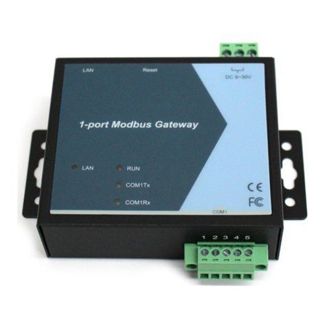
MB52XX Modbus Gateway
User Manual
V 1.0
MB52XX Series
Modbus Gateway
User Manual
V1.0
September 16th, 2019
Atop Technologies, Inc
.

MB52XX Modbus Gateway
User Manual
V 1.0
This PDF Document contains internal hyperlinks for ease of navigation.
For example, click on any item listed in the Table of Contents to go to that page.
Published by:
Atop Technologies, Inc.
2F, No. 146, Sec. 1, Tung-Hsing Rd,
30261 Chupei City,
Hsinchu County
Taiwan, R.O.C.
Tel: +886-3-550-8137
Fax: +886-3-550-8131
sales@atop.com.tw
www.atoponline.com

MB52XX Modbus Gateway
User Manual
V 1.0
Important Announcement
The information contained in this document is the property of Atop technologies, Inc., and is supplied for the sole
purpose of operation and maintenance of Atop Technologies, Inc., products.
No part of this publication is to be used for any other purposes, and it is not to be reproduced, copied, disclosed,
transmitted, stored in a retrieval system, or translated into any human or computer language, in any form, by any
means, in whole or in part, without the prior explicit written consent of Atop Technologies, Inc.,
Offenders will be held liable for damages and prosecution.
All rights, including rights created by patent grant or registration of a utility model or design, are reserved.
Disclaimer
We have checked the contents of this manual for agreement with the hardware and the software described. Since
deviations cannot be precluded entirely, we cannot guarantee full agreement. However, the data in this manual is
reviewed regularly and any necessary corrections will be included in subsequent editions.
Suggestions for improvement are welcome.
All other product’s names referenced herein are registered trademarks of their respective companies.
Documentation Control
Author:
Matteo Tabarelli
Revision:
1.0
Revision History:
Creation
Creation Date:
16 September 2019
Last Revision Date:
25 September 2019
Product Reference:
MB52XX Series Modbus Gateway User Manual
Document Status:
Creation

MB52XX Modbus Gateway
User Manual
V 1.0
Table of Contents
1Preface .................................................................................................................................7
1.1 Purpose of the Manual...........................................................................................................................7
1.2 Who Should Use This User Manual .......................................................................................................7
1.3 Supported Platform ................................................................................................................................7
1.4 Manufacturers’ FCC Declaration of Conformity Statement ................................................................7
2Introduction..........................................................................................................................8
2.1 Overview..................................................................................................................................................8
3Getting Started.................................................................................................................. 10
3.1 Packing List ......................................................................................................................................... 10
3.2 Appearance, Front and Rear Panels ................................................................................................... 11
3.3 First Time Installation ......................................................................................................................... 12
3.4 Factory Default Settings...................................................................................................................... 13
3.4.1 Network Default Settings .................................................................................................................... 13
3.4.2 Modbus Default Settings .................................................................................................................... 13
4Configuration and Setup .................................................................................................. 14
4.1 Configuration of Network Parameters through Device Management Utility ................................... 14
4.2 Configuring through Web Interface .................................................................................................... 16
4.3 Configuring Automatic IP Assignment with DHCP ........................................................................... 17
4.4 Web Overview ...................................................................................................................................... 17
4.5 Network Configuration ........................................................................................................................ 18
4.6 Basic Settings ...................................................................................................................................... 19
4.6.1 COM Settings....................................................................................................................................... 19
4.6.2 Operation Mode ................................................................................................................................... 20
4.6.3 Serial Settings...................................................................................................................................... 20
4.6.4 VCOM Settings .................................................................................................................................... 20
4.6.5 TCP Settings ........................................................................................................................................ 23
4.6.6 Slave ID Map ........................................................................................................................................ 25
4.7 Advanced Settings .............................................................................................................................. 27
4.7.1 SNMP Settings..................................................................................................................................... 27
4.7.2 Modbus ................................................................................................................................................ 30
4.8 Alert ...................................................................................................................................................... 30
4.8.1 Settings ................................................................................................................................................ 30
4.8.2 Alert Events.......................................................................................................................................... 31
4.9 System ................................................................................................................................................. 33
4.9.1 Log Settings......................................................................................................................................... 33
4.9.2 System Log .......................................................................................................................................... 33
4.9.3 Data Log............................................................................................................................................... 33
4.9.4 Modbus Statistic ................................................................................................................................. 34
4.9.5 Time ..................................................................................................................................................... 34
4.9.6 Security ................................................................................................................................................ 35
4.9.7 Import
/
Export ...................................................................................................................................... 36
4.9.8 Factory Default .................................................................................................................................... 38
4.10 Restart.................................................................................................................................................. 38
5Specifications ................................................................................................................... 40
5.1 Hardware.............................................................................................................................................. 40
5.2 Serial port Pin Assignments ............................................................................................................... 41
5.2.1 Pin Assignments for Serial Interfaces ............................................................................................... 41
MB52XX Modbus Gateway
User Manual
V 1.0
5.3 LED Indicators ..................................................................................................................................... 42
5.4 Software............................................................................................................................................... 42
6Warranty ............................................................................................................................ 43
Table of Figures
Figure 2.1 Possible Network Configuration of MB52XX Series Modbus Gateway .......................................................8
Figure 2.2 Use Cases of the MB52XX Series Modbus Gateway ....................................................................................9
Figure 4.1 List of Device in Device Management Utility............................................................................................... 14
Figure 4.2 Pull-down Menu of Configuration and Network.......................................................................................... 14
Figure 4.3 Pop-up Window of Network Setting ............................................................................................................ 15
Figure 4.4 Pop-up Notification Window after Authorization ....................................................................................... 15
Figure 4.5 Overview Web Page of Modbus Gateway ................................................................................................... 16
Figure 4.6 Map of Configuring Web Page on Modbus Gateway ................................................................................. 16
Figure 4.7 Overview Web Page...................................................................................................................................... 17
Figure 4.8 Network Web Page ....................................................................................................................................... 18
Figure 4.9 COM Settings Web Page .............................................................................................................................. 19
Figure 4.10 Save Successfully Message ...................................................................................................................... 20
Figure 4.11 VCOM Settings Web Page.......................................................................................................................... 21
Figure 4.12 Pull-down Menu of VCOM Mode............................................................................................................... 21
Figure 4.13 Check Box for Applying the Settings to All VCOMSs ............................................................................... 22
Figure 4.14 Modbus TCP Settings Web Page with TCP Slave Mode .......................................................................... 23
Figure 4.15 Modbus TCP Setting Page with TCP Master Operation Mode Selection ............................................... 24
Figure 4.16 Slave ID Map Page with Slave ID Setting in Alias Mode .......................................................................... 25
Figure 4.17 Slave ID Map Web Page with Slave ID Setting in in Offset Mode ........................................................... 26
Figure 4.18 SNMP Settings Web Page with SNMP disabled....................................................................................... 27
Figure 4.19 SNMP Settings Web Page with SNMP Enabled and Version v1/v2c/v3................................................. 28
Figure 4.20 SNMP Settings Web Page with SNMP Enabled and Version v1/v2c ...................................................... 29
Figure 4.21 SNMP Settings Web Page with SNMP Enabled and Version Only v3 ..................................................... 29
Figure 4.22 Advanced Modbus Settings of Response Timeout for Modbus Exception ............................................ 30
Figure 4.23 SMTP Settings Web Page .......................................................................................................................... 31
Figure 4.24 Alert Events Web Page............................................................................................................................... 32
Figure 4.25 Log Settings Web Page .............................................................................................................................. 33
Figure 4.26 System Log Web Page ............................................................................................................................... 33
Figure 4.27 Data Log Web Page .................................................................................................................................... 34
Figure 4.28 Modbus Statistics Web Page..................................................................................................................... 34
Figure 4.29 Time Web Page........................................................................................................................................... 35
Figure 4.30 Security Web Page ..................................................................................................................................... 36
Figure 4.31 Import/Export Web Page............................................................................................................................ 37
Figure 4.32 Export Configuration File from Modbus Gateway .................................................................................... 38
Figure 4.33 Factory Default Web Page ......................................................................................................................... 38
Figure 4.34 Restart Web Page....................................................................................................................................... 39
Figure 6.1 DB9 Pin Number ........................................................................................................................................... 41
Figure 6.2 TB5 Pin Number............................................................................................................................................ 42
List of Tables
Table 3.1 Packing List.................................................................................................................................................... 10

MB52XX Modbus Gateway
User Manual
Preface
Table 3.2 Description of Optional Accessories ............................................................................................................ 10
Table 3.3 Network Default Setting ................................................................................................................................ 13
Table 3.4 Modbus Default Settings............................................................................................................................... 13
Table 3.5 Other Default Settings ................................................................................................................................... 13
Table 6.1 Hardware Specification ................................................................................................................................. 40
Table 6.2 MB5201/MB5202 Pin Assignment for DB9 to RS-232/RS-422/RS-485 Connector.................................. 41
Table 6.3 MB5201/MB5202 Pin Assignment for TB5 to RS-232/RS-422/RS-485 Connector................................... 42
Table 6.4 Color Interpretation of LED Indicators.......................................................................................................... 42
Table 6.5 Software Tools and Utilities .......................................................................................................................... 42

MB52XX Modbus Gateway
User Manual
Preface
1Preface
1.1 Purpose of the Manual
This manual supports the user during the installation and configuring of the MB52XX Series Modbus Gateway. It
explains the technical features available with the mentioned product. As such, it contains some advanced network
management knowledge, instructions, examples, guidelines and general theories designed to help users manage
this device and its corresponding software. A background in general theory is necessary when reading it. Please
refer to the Glossary for technical terms and abbreviations (if any).
1.2 Who Should Use This User Manual
This manual is to be used by qualified network personnel or support technicians who are familiar with network
operations.It might be useful for system programmers or network planners as well. This manual also provides
helpful and handy information for first time users. For any related problems, please contact your local distributor.
If they are unable to assist you, please redirect your inquiries to www.atoponline.com.
1.3 Supported Platform
This manual is designed for MB52XX Series Modbus Gateway and that series only.
1.4 Manufacturers’ FCC Declaration of Conformity Statement
NOTE: This equipment has been tested and found to comply with the limits for a Class A digital device, pursuant to
Part 15 of the FCC Rules. These limits are designed to provide reasonable protection against harmful interference
when the equipment is operated in a commercial environment. This equipment generates, uses, and can radiate
radio frequency energy and, if not installed and used in accordance with the instruction manual, may cause harmful
interference to radio communications. Operation of this equipment in a residential area is likely to cause harmful
interference in which case the user will be required to correct the interference at his/her own expense.
This device complies with Part 15 of the FCC Rules. Operation is subject to the following two conditions:
1. This device may not cause harmful interference, and
2. This device must accept any interference received, including interference that may cause an undesired
operation.
Note: all the figures herein are intended for illustration purposes only. This software and certain features work only on certain Atop’s devices.

MB52XX Modbus Gateway
User Manual
Introduction
2Introduction
2.1 Overview
The MB52XX Modbus Gateway is an industrial network device in between Modbus over Serial Line devices and
computer hosts running Modbus/TCP on Ethernet network. Figure 2.1 illustrates a possible network configuration
of the MB52XX Series Modbus Gateway. Fully compliant with Modbus/TCP protocol, the Modbus gateway offers a
convenient solution to connect existing devices or controllers running Modbus serial protocol (Modbus/ASCII or
Modbus/RTU) to an Ethernet network. The MB52XX Series are standard Modbus gateways that convert packets
between Modbus TCP and Modbus RTU/ASCII protocols.
The MB52XX Series supports 64 simultaneous TCP masters. Overall, 247 Servers are supported (TCP, COM and
VCOM). Each RS-232/422/485 serial port can be individually configured for Modbus/RTU or Modbus/ASCII
operation with different baud rate, allowing both types of networks to be fully integrated with Modbus/TCP within
one package.
Figure 2.1 Possible Network Configuration of MB52XX Series Modbus Gateway

MB52XX Modbus Gateway
User Manual
Introduction
Figure 2.2 shows three different use cases of the MB52XX Series Modbus Gateway:
1) the interface between Modbus RTU/ASCII serial host to Modbus RTU/ASCII serial devices
2) the interface between Modbus/TCP over Ethernet network to Modbus RTU/ASCII serial devices
3) the interface between Modbus RTU/ASCII host connected through Serial IP over Ethernet (virtual
communication port (VCOM)) to Modbus RTU/ASCII serial devices.
Figure 2.2 Use Cases of the MB52XX Series Modbus Gateway
Caution
Beginning from here, extreme caution must be exercised.
Never install or work with electricity or cabling during periods of lightning
activity. Never connect or disconnect power when hazardous gases are
present.
Warning: HOT!
WARNING:Disconnect the power and allow unit to cool for 5 minutes before touching.

MB52XX Modbus Gateway
User Manual
Getting Started
3Getting Started
3.1 Packing List
Inside the purchased package, you will find the following items.
Table 3.1 Packing List
Item
Quantity
Description
MB52XX
1
Industrial Serial Device Server
Mounting Kit
1
Wall-mounting screws (DIN-rail kit is optional)
Terminal Block
Power Supply:
TB3 x 1: 3-pin 5.08mm Terminal Block
Serial ports: Terminal block is included only on –TB or –SiS models
TB5 x 1: 5-pin 5.08mm lockable Terminal Block (MB5201)
TB5 x 2: 5-pin 5.08mm lockable Terminal Block (MB5202)
Documentation
1
Hardware Installation Guide (Warranty card is included)
Note:
Notify your sales representative immediately if any of the above items is missing or damaged upon delivery.
Atop’s utility software Device View© and Serial Manager© are obsolete and replaced by Device
Management Utility®.
Table 3.2 Description of Optional Accessories
Optional Accessories
Model Name
Part Number
Description
DK-25
30200000000022G
Plastic DIN Rail Kit
ADP-DB9(F)-TB5
59906231G
Female DB9 to Female 3.81mm, a TB5 Converter
UN315-1212(US-Y)
50500151120003G
Y-Type power adaptor, 100~240VAC input, 1.25A @ 12VDC
output, US plug, LV6
UNE315-1212(EU-Y)
50500151120013G
Y-Type power adaptor, 100~240VAC input, 1.25A @ 12VDC
output, EU plug, LV6
UV305-0510(US-DC)
50500051500003G
DC jack (3.5/1.35/7.5 mm) power adapter, 100~240VAC input,
1.0A@ 5VDC output, US plug, LV6
UVE305-0510(EU-
DC)
50500051500013G
DC jack (3.5/1.35/7.5 mm) power adapter, 100~240VAC input,
1.0A@ 5VDC output, EU plug, LV6
UVE305-0510(UK-
DC)
50500051500023G
DC jack (3.5/1.35/7.5 mm) power adapter, 100~240VAC input,
1.0A@ 5VDC output, UK plug, LV6

MB52XX Modbus Gateway
User Manual
Getting Started
3.2 Appearance, Front and Rear Panels
The following figures show particular MB520X series device’s front, back, side and top panels.
MB5201C –Entry-Level Semi-Industrial Modbus Gateway
MB5201 –Industrial 1-Port Modbus Gateway
MB5202 –Industrial 2-Port Modbus Gateway

MB52XX Modbus Gateway
User Manual
Getting Started
3.3 First Time Installation
Before installing the device, please follow strictly all safety procedures described in the Hardware installation guide
supplied inside the product. Atop will not be liable for any damages to property or personal injuries resulting from
the installation or overall use of the device. Do not attempt to manipulate the product in any way if unsure of the
steps described there. In such cases, please contact your dealer immediately.
Specific installation instructions are not provided in this manual since they may differ considerably based on the
hardware purchased.

MB52XX Modbus Gateway
User Manual
Getting Started
3.4 Factory Default Settings
3.4.1 Network Default Settings
The MB520X Industrial Modbus Gateway is equipped with one LAN interface with one default IP address. Its default
network parameters are listed in Table 3.3.
Table 3.3 Network Default Setting
Interface
Device IP
Subnet Mask
Gateway IP
DNS
LAN1
10.0.50.100
255.255.0.0
10.0.0.254
0.0.0.0
3.4.2 Modbus Default Settings
The MB52XX Modbus Gateway comes with the following default Modbus settings.
Table 3.4 Modbus Default Settings
Parameter
Default Values
Modbus Master
TCP Settings
TCP Master Mode: TCP Master
Port: 502
Modbus Slave
MB5201
MB5202
Mode: RTU Slave
Serial Configuration: RS-232, 9600 bps, 8 data bits, No
parity bit, 1 stop bit, No Flow Control, Buffer Disable
Other default settings are shown in the following table.
Table 3.5 Other Default Settings
Parameter
Default Values
Security
User Name
admin
Password
default
SNMP
SysName of SNMP
atop
SysLocation of SNMP
Location
SysContact of SNMP
Contact
SNMP
Disable (Unchecked)
Read Community
Public
Write Community
Private
SNMP Trap Server
0.0.0.0
Note: Press the “Reset” button on the front panel for 5 seconds (see Section 4.9.8 and Section 4.10), to restore the
MB52XX Series Modbus Gateway to the factory default settings.

MB52XX Modbus Gateway
User Manual
Configuration and
Setup
4Configuration and Setup
It is strongly recommended for the user to set the Network Parameters through Device Management Utility© first.
Other device-specific configurations can later be carried out via Atop’s user-friendly Web-Interface.
4.1 Configuration of Network Parameters through Device Management Utility
First, please install Atop’s configuration utility program called Device Management Utility® that comes with the
Product CD or can be downloaded from or website www.atoponline.com. For more information on how to install
Device Management Utility®, please refer to the manual that comes in the Product CD. After you start Device
Management Utility®, if the Modbus Gateway is already connected to the same subnet as your PC, the device can
be accessed via broadcast packets. Device Management Utility® will automatically detect your Modbus Gateway
and list it on Device Management Utility®’s window. Alternatively, if you did not see your Modbus Gateway on your
network, press “Rescan” icon, a list of devices, including your Modbus Gateway device currently connected to the
network will be shown in the window of Device Management Utility® as shown in Figure 4.1.
Figure 4.1 List of Device in Device Management Utility
Note:This figure is for illustration purpose only. Actual values/settings may vary between devices.
Sometime the Modbus Gateway device might not be in the same subnet as your PC; therefore, you will have to use
Atop's utility to locate it in your virtual environment. To configure each device, first click to select the desired
Modbus Gateway device (default IP: 10.0.50.100) in the list of Device Management Utility©, and then click
“Configuration Network…” (or Ctrl+N) menu on Device Management Utility© as shown in Figure 4.2 or click on
the second icon called Network on the menu icon bar, and a pop-up window will appear as shown in Figure 4.3.
Figure 4.2 Pull-down Menu of Configuration and Network...

MB52XX Modbus Gateway
User Manual
Configuration and
Setup
Figure 4.3 Pop-up Window of Network Setting
You may proceed then to change the IP address to avoid any IP address conflict with other hosts on your LAN or
to connect the device to your existing LAN as shown in Figure 4.3. The system will prompt you for a credential to
authorize the changes. It will ask you for the Username and the Password. The default username is “admin”, while
the default password “default”. After clicking on the Authorize button, a notification window will pop-up as shown
in Figure 4.4 and some device may be restarted. After the device is restarted (for some model), it will beep twice to
indicate that the unit is running normally. Then, the Modbus Gateway can be found on a new IP address. It may be
listed automatically by the Device Management Utility© or it can be found by clicking on the “Rescan”icon.
Figure 4.4 Pop-up Notification Window after Authorization
Please consult your system administrator if you do not know your network’s subnet mask and gateway address.

MB52XX Modbus Gateway
User Manual
Configuration and
Setup
4.2 Configuring through Web Interface
Every MB52XX Modbus Gateway device is equipped with a built-in web server in the firmware. Therefore, the device
can be accessed by using a web browser for configuring by entering the device’s IP address (default IP address is
10.0.50.100) in the URL field of your web browser. Figure 4.5 illustrates the overview page of the web interface.
Please see Section 0 for default values.
Figure 4.5 Overview Web Page of Modbus Gateway
Figure 4.6 Map of Configuring Web Page on Modbus Gateway

MB52XX Modbus Gateway
User Manual
Configuration and
Setup
This approach for configuring your device is the most user-friendly. It is the most recommended and the most
common method used for MB52XX Series Modbus Gateway. Please go to its corresponding section for a detailed
explanation.
4.3 Configuring Automatic IP Assignment with DHCP
A DHCP server can automatically assign IP addresses, Subnet Mask and Network Gateway interface. You can
simply check the “DHCP (Obtain an IP Automatically)” checkbox in the Network Setting dialog as shown in Figure
4.3 using Atop’s Device Management Utility© and then restart the device. Once restarted, the IP address will be
configured automatically.
4.4 Web Overview
In this section, current information on the device’s status and settings will be displayed. An example of MB5202-
TB overview page is shown in Figure 4.7.
Figure 4.7 Overview Web Page
In detail, the following information is given:
Model Name, as its name implies, shows the device’s model
Device Information displays information on the Kernel version as well as the AP version of your Modbus
Gateway device.
Network Information shows MAC and IP addresses for the LAN port.

MB52XX Modbus Gateway
User Manual
Configuration and
Setup
4.5 Network Configuration
In this section, IP address, Subnet Mask, Default (Network) Gateway, Domain Name System (DNS) and overall
connectivity settings of Modbus Gateway device can be accessed as shown in Figure 4.8. For the LAN Interface
Settings, you can check the corresponding DHCP box to obtain an IP address, Subnet Mask, and Default (Network)
Gateway automatically.
Figure 4.8 Network Web Page
At the lowest box in Figure 4.8, you will have the DNS Settings box which allows you to set the IP addresses of
Domain Name Server 1 (DNS 1) and Domain Name Server 2 (DNS 2) for redundancy. If the device is connected to
the Internet and should connect to other servers over the Internet to get some services such as Network Time
Protocol (NTP) server, the user will need to configure the DNS server in order to be able to resolve the host name
of the NTP server. Please consult your network administrator or internet service provider (ISP) to obtain local DNS’s
IP addresses.

MB52XX Modbus Gateway
User Manual
Configuration and
Setup
4.6 Basic Settings
In this section, the term “Modbus Gateway device”will be used to refer to the MB52XX series and the term “serial
device”to refer to any Modbus device that connect to Modbus Gateway via COM, VCOM, or TCP connections. In
any Modbus network, there are two types of Modbus devices: Modbus Master and Modbus Slave. The Modbus
Master will send a request message to a Modbus Slave. Then, the Modbus Slave will respond to the Modbus
Master’s request. A Modbus device (serial device) that is connected to the MB52XX series Modbus Gateway device
will either assume a role of Modbus Master or Modbus Slave. The basic settings in this section will address how
to configure the role of the serial device in your Modbus Gateway device and its serial communication parameters.
The term “Operation Mode”will be used to refer to the combination of role (Master or Slave) and the message or
data transfer types (RTU/ASCII/TCP) of the Modbus protocol used by the serial device.
4.6.1 COM Settings
This section shows how to set up the physical ports of the Modbus Gateway device (COM ports or serial ports that
serial devices are connected to). The available number of COM ports may vary according to the chosen Modbus
Gateway model. Figure 4.9 shows the COM Settings web page in which COM1 port is shown with its Operation
Mode under Modbus Setting and Serial Configuration settings. These settings will configure the role of the serial
device through the Operation Mode and the serial communication parameters of that serial device through the
Serial Configuration settings.
Figure 4.9 COM Settings Web Page

MB52XX Modbus Gateway
User Manual
Configuration and
Setup
4.6.2 Operation Mode
To set the Operation Mode of the serial device that is connected to the Modbus Gateway through a COM port, use
the pull-down menu to select among the following modes under Modbus Setting.
RTU Slave: The serial device is working as a Modbus Slave node: the serial device will wait, accept request
from, and response to its Modbus Master node. Data transfer is done in RTU format.
RTU Master: The serial device is working as a Modbus Master node: the serial device will issue commands
to or query Modbus slave nodes. Data transfer is done in RTU format.
ASCII Slave: The serial device is working as a Modbus Slave node: the serial device will wait, accept request
from, and response to its Modbus Master node. Data transfer is done in ASCII format.
ASCII Master: The serial device is working as a Modbus Master node: the serial device will issue
commands to or query Modbus Slave nodes. Data transfer is done in ASCII format.
4.6.3 Serial Settings
This section summarizes the options of serial communication parameters used between the serial device and the
Modbus Gateway device over the selected COM port.
RS-232/RS-422/RS-485 (2-wire) Software Selectable
Baud-rate: 1200 bps ~ 921600 bps Software Selectable
Parity: None, Odd, Even, Mark, or Space
Data Bits: 7 or 8
Stop Bits: 1 or 2
Flow Control: None, Software Xon/Xoff, Hardware RTS/CTS
Receiver Resistor: On or Off
Apply to all Serial Ports (check box): The settings can be chosen to apply to all serial ports if needed by checking
the last checkbox on the options.
After finish the COM Settings configuration, click the Save Configuration button to save all changes that have been
made. A Save Successfully message will show up as shown in Figure 4.10 and after a short period of time the web
browser will be redirected back to COM Settings page (Figure 4.9).
Figure 4.10 Save Successfully Message
4.6.4 VCOM Settings
These settings will generate a virtual Serial (VCOM) port within the Modbus Gateway device based on a TCP
network connection. VCOM is a TCP connection which is encoded in an Atop Technologies’ exclusive private
protocol. MB52XX series Modbus Gateway can only run as a TCP server which will be waiting for a connection
request from a TCP client (a serial device).
Figure 4.11 shows the page of VCOM Settings in which the VCOM number 1 is set as an RTU Slave. This means
that a device that is connected to this VCOM port on the Modbus Gateway will be a Modbus Slave node and
communicate with a Modbus Master node using Modbus/RTU protocol. It is an interface concept that allows
Modbus Slave devices to be connected via TCP connection by using VCOM from a PC (for example). If a VCOM
This manual suits for next models
3
Table of contents
Other Atop Gateway manuals

Atop
Atop MB5001C User manual

Atop
Atop MB5001C User manual

Atop
Atop MB5400 User manual

Atop
Atop MB5904D User manual

Atop
Atop CR5201B Series User manual

Atop
Atop MB5201 Series Manual

Atop
Atop PG5901B Series Instruction sheet

Atop
Atop MB5404D Series User manual

Atop
Atop PG5901B Series Instruction sheet

Atop
Atop SE5901 Series Manual
Popular Gateway manuals by other brands

ASTRO
ASTRO Fibre WiFi Kencang user manual

SMC Networks
SMC Networks EZ Connect 2.4GHz 54Mbps Wireless Cable Modem Gateway... specification

Atlantis Land
Atlantis Land A07-VTG3306C Specification sheet

AudioCodes
AudioCodes MP-5 Series Configuration guide

Libelium
Libelium Meshlium Xtreme Technical guide

Dinstar
Dinstar DAG1000-4S4O Quick installation guide