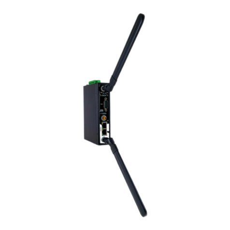
Atop PG5901B Series Instruction sheet

Protocol Gateway
DNP3.0 Client/Server
Protocol and
eNode Designer configuration
eNode Configuration Manual
V1.5
August 3rd, 2023
ATOP Technologies, Inc.

DNP3
eNode Configuration Manual
Page 2 of 66
This PDF Document contains internal hyperlinks for ease of navigation.
For example, click on any item listed in the Table of Contents to go to that page.
Configuration Guide
Interoperability
Published by:
ATOP Technologies, Inc.
2F, No. 146, Sec. 1, Dongxing Rd.,
Zhubei City, Hsinchu County,
302058, Taiwan, R.O.C.
Tel: +886-3-550-8137
Fax: +886-3-550-8131
https://www.atoponline.com

DNP3
User Manual
Page 3 of 66
Important Announcement
Copyright
© 2005-2023 SystemCORP
© 2016-2023 ATOP Technologies, Inc.
The information contained in this document is the property of ATOP technologies, Inc., and is supplied for the
sole purpose of operation and maintenance of ATOP Technologies, Inc., products.
No part of this publication is to be used for any other purposes, and it is not to be reproduced, copied, disclosed,
transmitted, stored in a retrieval system, or translated into any human or computer language, in any form, by any
means, in whole or in part, without the prior explicit written consent of ATOP Technologies, Inc.,
Offenders will be held liable for damages and prosecution.
All rights, including rights created by patent grant or registration of a utility model or design, are reserved.
Disclaimer
We have checked the contents of this manual for agreement with the hardware and the software described. Since
deviations cannot be precluded entirely, we cannot guarantee full agreement. However, the data in this manual is
reviewed regularly and any necessary corrections will be included in subsequent editions.
Suggestions for improvement are welcome.
All other product’s names referenced herein are registered trademarks of their respective companies.
Documentation Control
Author:
Simon Huang
Revision:
1.5 update
Revision History:
Update copyright and ATOP contact information
Creation Date:
12 April 2017
Last Revision Date:
3 August 2022
Reviewer
Simon Huang
Product Reference:
PG59XX Protocol Gateways
Document Status:
Released

DNP3
User Manual
Page 4 of 66
Table of Contents
1Introduction .....................................................................................................................6
1.1 Scope ....................................................................................................................................................6
1.2 Document Reference.............................................................................................................................6
1.3 List of Abbreviations..............................................................................................................................6
2General Description .........................................................................................................8
2.1 Configuration Theory.............................................................................................................................8
2.2 General Screen Description ..................................................................................................................9
3DNP3 Configuration Guide.............................................................................................10
3.1 Adding the Module in eNode Designer................................................................................................10
3.2 Server IED Properties .........................................................................................................................10
3.2.1.1 Slave Address ................................................................................................................11
3.2.1.2 IP Address .....................................................................................................................11
3.2.1.3 IP Port............................................................................................................................11
3.3 Client Configuration.............................................................................................................................12
3.3.1 Client Settings....................................................................................................................13
3.3.1.1 Master Address .............................................................................................................13
3.3.1.2 Communication Medium ...............................................................................................13
3.3.1.3 Link Layer Timeout (ms).................................................................錯誤! 尚未定義書籤。
3.3.1.4 Application Layer Timeout (ms) ....................................................................................13
3.3.1.5 Class 0, 1, 2, 3 Poll Interval (ms)....................................................................................14
3.3.1.6 Class 0 Poll Interval (ms)...............................................................................................14
3.3.2 Adding Data Points ............................................................................................................13
3.3.3 Servers (Remote IEDs) .......................................................................................................16
3.4 Server Configuration............................................................................................................................17
3.4.1 Server Settings...................................................................................................................18
3.4.1.1 Master Address .............................................................................................................18
3.4.1.2 Communication Medium ...............................................................................................18
3.4.1.3 Enable Self Address.......................................................................................................18
3.4.1.4 Class {X} Event Buffer Size ............................................................................................19
3.4.1.5 Class {X} Event Buffer Overflow Percentage .................................................................19
3.4.1.6 Default Static Variations................................................................................................19
3.4.1.7 Default Event Variations ................................................................................................19
3.4.2 Adding Data Point References ...........................................................................................21
3.5 Miscellaneous Common......................................................................................................................22
3.5.1 Incomplete, Conflicting and not needed Information ........................................................22
3.5.2 Modify Selected Points Window ........................................................................................23
4Communication Port Properties ....................................................................................24
5Using Auto-increment Counters.....................................................................................25
5.1 Automatic Increments in Constant Values ..........................................................................................26
6Reference Guide ............................................................................................................27
6.1 Table Buttons ......................................................................................................................................27
6.2 Table Columns ....................................................................................................................................27
6.2.1.1 Tag.................................................................................................................................27
6.2.1.2 Groups ...........................................................................................................................27
6.2.1.3 Start Address.................................................................................................................27
6.2.1.4 Count .............................................................................................................................28
DNP3
User Manual
Page 5 of 66
6.2.1.5 Operation Mode .............................................................................................................28
6.2.1.6 Analog Input Deadband .................................................................................................28
6.2.1.7 SBO Timeout (ms) .........................................................................................................28
6.3 DNP3’s Related ADH Types ...............................................................................................................28
7DNP3 Client Properties ..................................................................................................30
7.1 Device Profile ......................................................................................................................................30
7.2 Implementation Table..........................................................................................................................33
8DNP3 Server Properties .................................................................................................48
8.1 Device Profile ......................................................................................................................................48
8.2 Implementation Table..........................................................................................................................52
Table of Figures
Figure 2-1 - Example Screen.......................................................................................................................................9
Figure 3-1 - Adding the module in eNode Designer. .................................................................................................10
Figure 3-2 - Client settings panel (serial above; Ethernet below)..............................................................................12
Figure 3-3 - Client IED panel (Ethernet).....................................................................................................................12
Figure 3-4 - Add data points window. .......................................................................................................................15
Figure 3-5 - Multiple connected servers example.....................................................................................................16
Figure 3-6 - Add a connected server.........................................................................................................................16
Figure 3-7 –Remove a connected server.................................................................................................................16
Figure 3-8 - Server settings panel extract. ................................................................................................................17
Figure 3-9 –Server IED panel. ..................................................................................................................................18
Figure 3-10 - Add new references window. ..............................................................................................................21
Figure 3-11 - Data point references added. ..............................................................................................................21
Figure 3-13 - Modify data points window example...................................................................................................23
Figure 4-1 - Serial port properties. ............................................................................................................................24
Figure 4-2 –Ethernet port properties.......................................................................................................................24

DNP3
User Manual
Page 6 of 66
1Introduction
Thank you for Buying ATOP’s Protocol Gateway.
The product is bundled with the following three user manuals:
1) Hardware specific installation user manual, not covered in this document. It covers ATOP’s hardware
installation procedure, wiring, power connection etc.
2) Getting started with ATOP’s Protocol Gateway user manual – configuration tool introduction, web
configuration, software architecture introduction–not covered in this document. This manual covers the
introduction, installation, network set-up maintenance and using of the configuration tool software,
including the procedure to be followed for uploading new configurations to ATOP’s device.
3) Protocol specific user manual (This Manual). One protocol-specific manual will be provided for each
protocol installed on the device. This manual covers:
a. Basic device network configuration
b. Step-by-step protocol set-up for in eNode designer
c. Description of the protocol-specific software features, the device profile and the implementation
table of supported functionalities.
This manual is for DNP3.0 Client/Server and describes how to use the DNP3 eNode Designer Module to configure
ATOP’s DNP3 ADH Application within the eNode Designer configuration tool.
1.1 Scope
This document is divided into 3 major sections:
•General Description;
•Configuration Guide; and
•DNP3.0 Client Device Profile/ Implementation table and
•DNP3.0 Server Device Profile/ Implementation table
1.2 Document Reference
[1] Document Title: Getting started User Manual: 197-0100
Revision: Version 1.00 or higher
[2] Document Title: DNP3 Specification
Revision: 2.05, 24th June 2009
1.3 List of Abbreviations
ADH = Application Data Hub
DNP3 = Distributed Network Protocol 3
IED = Intelligent Electronic Device
IP = Internet Protocol

DNP3
User Manual
Page 7 of 66
TCP = Transmission Control Protocol

DNP3
User Manual
Page 8 of 66
2General Description
The DNP3 eNode Module can be used to configure the DNP3 ADH Application as a master or slave. For naming
consistency across eNode Designer, the master is called a client, and the slave is called a server.
The DNP3 client can communicate with many DNP3 server IEDs, all of whose data point details can be configured
using this module.
2.1 Configuration Theory
Most configuration properties describe a server. When configuring the ADH application server, you are configuring
the properties of the server itself. ATOP protocol gateway supports one server application per protocol per port.
When configuring the ADH Application client, you are describing the properties of all the remote servers with whom
the client is communicating.
Configuring the protocol-specific information, such as object addresses, is handled in the module. This is explained
in this document.
Communication port properties (such as Baud Rate) are configured on the communication port itself. The Device
module handles the communication port properties, so heavy details are outside the scope of this document.
Port configuration instructions are provide in the eNode Designer general user manual.
Screenshots of the typical configuration method are anyway shown in section 4. The relevant properties of the
communication ports automatically apply to the application. For example, in a DNP3 server application, the IP
Address the application binds to is taken from the parent Ethernet port.

DNP3
User Manual
Page 9 of 66
2.2 General Screen Description
A small configuration example is shown below to better help describe the layout of the screen.
Figure 2-1 - Example Screen
Tabs
Server IED Properties –Describes the protocol-specific properties of the server IED.
Data Table and buttons –Shows all (information) data associated with the IED, and shows the buttons to
be used to modify them.
Commands Table and buttons –Shows all commands associated with the IED, and shows the buttons to
be used to modify them.
The user is able edit contents of the data and commands tables freely.
1
2
3
4
1
2
3
4

DNP3
User Manual
Page 10 of 66
3DNP3 Configuration Guide
3.1 Adding the Module in eNode Designer
The DNP3 module can be added to both Ethernet and Serial ports.
The application can be set up as a Client or a Server. The choice will be presented when adding it to the project.
Figure 3-1 - Adding the module in eNode Designer.
Right click the desired communication port.
Open the Add ADH Application menu.
Select DNP3.
Select Client or Server from the drop-down menu.
Click OK.
3.2 Server IED Properties
The server IED properties are at the top of the module screen. The options available are limited to what is relevant
for the communication port.
Serial port example:
Ethernet port example:
Each property is described in detail below.
4
5
1
2
3
1
2
3
4
5

DNP3
User Manual
Page 11 of 66
3.2.1.1 Slave Address
Description
The slave address of the server IED. For servers it describes its own slave address.
For clients, it describes the slave address of the remote server.
Data Entry
Integer
Range
0 to 65519
Input Option
Mandatory
3.2.1.2 IP Address
Ethernet and Client only
Description
The IP Address of the remote server IED. This option is only available in clients, since
in servers, the IP Address is taken from the Ethernet port.
Data Entry
IP Address String
Range
Valid IPv4 Addresses (0.0.0.0 to 255.255.255.255)
Input Option
Mandatory
3.2.1.3 IP Port
Ethernet only
Description
The IP Port used by the server IED.
Data Entry
Integer
Range
1 to 65535. Default: 20000
Input Option
Mandatory

DNP3
User Manual
Page 12 of 66
3.3 Client Configuration
Adding a DNP3 client application will immediately show the following figure. The first tab shows the settings that
apply to the whole client application. Each tab after this shows a single DNP3 server with which the client is
communicating. Each tab is named “IED [{X}]” where {X} is the slave address.
Figure 3-2 - Client settings panel (serial above; Ethernet below).
Selecting the IED tab will show the following view.
Figure 3-3 - Client IED panel (Ethernet).
Here the “Add” and “+1” button can be used to add data points. Adding data points is explained in the “Add data
points” section, and the other buttons are described in section 6: Reference Guide.

DNP3
User Manual
Page 13 of 66
3.3.1 Protocol Settings
3.3.1.1 Master Address
Description
The DNP3 master address to use.
Data Entry
Integer
Range
0 to 65519
Input Option
Mandatory
3.3.1.2 Communication Medium
Description
The communication method to use. The list will automatically be restricted based on
the parent’s port type.
Data Entry
Drop down menu
Options
Serial, TCP, UDP
Input Option
Mandatory
3.3.1.3 Enable Unsolicited After Connection Establish
Description
Whether the client enables the server’s unsolicited message or not.
Data Entry
Checkbox
Types
Checked or not (default: checked)
Input Option
Mandatory
3.3.2 IED Settings
3.3.2.1 Slave Address
Description
The DNP3 address of IED to use.
Data Entry
Integer
Range
0 to 65519 (default: 1)
Input Option
Mandatory
3.3.2.2 Link Layer Timeout (ms)
Description
The timeout for a data link layer confirmation in milliseconds.
Data Entry
Integer
Range
100 to 65535 (default: 2000)
Input Option
Mandatory
3.3.2.3 Application Layer Timeout (ms)
Description
The timeout for an application layer confirmation in milliseconds.
Data Entry
Integer
Range
2000 to 65535 (default: 10000)
Input Option
Mandatory

DNP3
User Manual
Page 14 of 66
3.3.2.4 Class 1, 2, 3 Poll Interval (ms)
Description
The poll interval of the event classes: class 1, 2 and 3. Every poll interval all event
classes are polled. Measured in milliseconds.
Data Entry
Integer
Range
1000 to 65535 (default: 1000)
Input Option
Mandatory
3.3.2.5 None Class / Class 0123 Poll Interval (ms)
Description
The poll interval of static data and all events. Every poll interval all data is polled for
its present value: class 0, 1, 2 and 3. Measured in milliseconds.
Data Entry
Integer
Range
1000 to 65535 (default: 10000)
Input Option
Mandatory

DNP3
User Manual
Page 15 of 66
3.3.3 Adding Data Points
To add data points, left click the “Add” button beneath the tables in the main view. Doing so will show the following
window. The window is used to add many data points at once with the specified values. For details on the meaning
of each column, see section 6.2.
Figure 3-4 - Add data points window.
Preview Area –Shows the preview of the data points that will be added.
New values –This area is used to enter values. Tag, Start Address and Count use manual data entry (click
the box and type new values). Group, Operation Mode use drop-down menus. Entering an integer into the
address column will start at that number and automatically increment in each successive point.
Number of rows –This counter can be used to add many data points at once.
Automatic Counters –These counters can be used to add many data points at once. The starting values
and step values can be changed in this area. See also 5 Using Auto-increment Counters.
OK button –to accept the new data points.
1
2
3
4
5
1
2
3
4
5

DNP3
User Manual
Page 16 of 66
3.3.4 Servers (Remote IEDs)
Each slave IED is represented by a single tab and a tree node in the eNode Designer project tree.
Figure 3-5 - Multiple connected servers example.
To modify the connected IEDs list follow the instructions below:
To add a new remote IED, click the “+” tab at the end of the existing remote server(s) list.
Figure 3-6 - Add a connected server.
To remove a remote IED, it must have no data points specified. If there are data points in the table and you still
wish to remove the IED, you will have to remove such data points first.
To remove a remote IED, click the cross on the right side of the tab of the IED you wish to remove.
Figure 3-7 –Remove a connected server.
1
1
1
1

DNP3
User Manual
Page 17 of 66
3.4 Server Configuration
A DNP3 server application outputs data from the ADH database, receives commands and passes them into the
ADH system to command another application to perform the operation. Therefore, all server operations use data
point references to already existing data points that have been created by other application clients or client-servers.
ATOP protocol gateway supports one server application per protocol per device.
The options describe the local server itself. The settings tab can be used to set the local settings, while the IED tab
is similar to the client-tab. Example figures of both are shown below.
Figure 3-8 - Server settings panel extract.

DNP3
User Manual
Page 18 of 66
Figure 3-9 –Server IED panel.
Here the “Add Reference” button can be used to add data point references. The procedure is explained fully in the
next section. The other buttons are described in section 6: Reference Guide.
3.4.1 Server Settings
All server settings are explained in the headings below.
3.4.1.1 Master Address
Description
The DNP3 master address to be used.
Data Entry
Integer
Range
0 to 65519
Input Option
Mandatory
3.4.1.2 Communication Medium
Description
The communication method to be used. The list will automatically be restricted
based on the parent’s port type.
Data Entry
Drop down menu
Options
Serial, TCP, UDP
Input Option
Mandatory
3.4.1.3 Enable Self Address
Description
The value of the “Enable self address” flag when the application is started. When
unsolicited responses are enabled, unsolicited messages may be sent.

DNP3
User Manual
Page 19 of 66
Data Entry
Checkbox
Range
Checked or not (default: checked)
Input Option
Mandatory
3.4.1.4 Class {X} Event Buffer Size
Description
The buffer size for class {X}: the maximum number of events to store.
Data Entry
Integer
Range
10 - 65535
Input Option
Mandatory
3.4.1.5 Class {X} Event Buffer Overflow Percentage
Description
If the buffer for class {X} fills to this percentage, a buffer overflow event is sent to
the master station.
Data Entry
Integer
Range
25-100. Recommended 50-95. Default: 90
Input Option
Mandatory
3.4.1.6 Default Static Variations
Description
The default static variations.
Data Entry
Drop down menus
Options
Binary Input
"With Flags"
Double Binary Input
"With Flags"
Counter Input
"32-bit With Flag", "16-bit With Flag", "32-bit Without Flag", "16-bit Without Flag"
Frozen Counter
Input
"32-bit With Flag", "16-bit With Flag", "32-bit With Flag and Time", "16-bit With Flag
and Time", "32-bit Without Flag", "16-bit Without Flag"
Analog Input
"32-bit With Flag", "16-bit With Flag", "32-bit Without Flag", "16-bit Without Flag",
"Single-prec Flt-pt With Flag"
Analog Input
Deadband
"16-bit", "32-bit", "Single-prec Flt-pt"
Binary Output
"With Flags"
Analog Output
"32-bit With Flag", "16-bit With Flag", "Single-prec Flt-pt With Flag"
Input Option
Mandatory
3.4.1.7 Default Event Variations
Description
The default event variations.
Data Entry
Drop down menus
Options
Binary Input
"Without Time", "With Absolute Time", "With Relative Time"

DNP3
User Manual
Page 20 of 66
Double Binary Input
"Without Time", "With Absolute Time", "With Relative Time"
Counter Input
"32-bit With Flag", "16-bit With Flag", "32-bit With Flag and Time", "16-bit With
Flag and Time"
Frozen Counter
Input
"32-bit With Flag", "16-bit With Flag", "32-bit With Flag and Time", "16-bit With
Flag and Time"
Analog Input
"32-bit Without Time", "16-bit Without Time", "32-bit With Time", "16-bit With
Time", "Single-prec Flt-pt Without Time", "Single-prec Flt-pt With Time"
Input Option
Mandatory
Other manuals for PG5901B Series
1
Table of contents
Other Atop Gateway manuals

Atop
Atop MB5400 User manual

Atop
Atop MB5201 Series Manual

Atop
Atop MB5904D User manual

Atop
Atop SE5901 Series Manual

Atop
Atop MB52 Series User manual

Atop
Atop PG59 Series User manual

Atop
Atop MB5404D Series User manual

Atop
Atop MB5404D-X Series Manual

Atop
Atop PG5901B Series Instruction sheet

Atop
Atop MB5001C User manual