Avdel 7611 User manual
P n e u m a t i c P o w e r T o o l
Pass onto user to read and keep for reference
I n s t r u c t i o n M a n u a l
0761 type
07611 - 07613 - 07614

AVDEL policy is one of continuous development. Specifications shown in this document may be subject to changes which
may be introduced after publication. For the latest information always consult Avdel.
S P E C I F I C A T I O N S F O R 0 7 6 1 T Y P E T O O L
■
■
■
■
■
■
■
■
■
■
■
■
■
■
■
■
■
■
■
■
■
■
■
■
■
■
■
■
■
■
■
■
■
■
■
■
■
■
■
■
■
■
AIR PRESSURE Minimum - Maximum 5 - 7 bar 70 - 100 lbf/in 2
FREE AIR VOLUME REQUIRED @ 5.4 bar / 80 lbf/in 23.5 litres 0.12 ft 3
STROKE 07611 Minimum 25.4 mm 0.95 in
07613/4 Minimum 17.3 mm 0.68 in
PULL FORCE 07611 @ 4.8 bar / 70 lbf/in 210.91 kN 2450 lbf
07613/4 @ 5.4 bar / 80 lbf/in 218.68 kN 4200 lbf
CYCLE TIME 07611/3 Approximately 1.5 seconds
07614 Approximately 1.3 seconds
NOISE LEVEL 07611 73 dB(A)
07613/4 Less than 70 dB(A
WEIGHT 07611 Without nose equipment 2.7 kg 6 lb
07613/4 Without nose equipment 3 kg 6.6 lb
VIBRATION 07611/4 2.6 m/s 28.5 f/s 2
07613 Less than 2.5 m/s 28 f/s 2

CO N T E N T S
CO N T E N T S
1
S A F E T Y
I N T E N T O F U S E
P U T T I N G I N T O S E R V I C E
N O S E A S S E M B L I E S
S E R V I C I N G
P R I M I N G
F A U L T D I A G N O S I S
General
2
Specific to 0761 Tool
3
Selection & Dimensions
4-5
Air Supply
6
Operating Procedure
6-7
Accessories
7
Fitting/Servicing/Components
8-9
Daily, Weekly
10
Service Kit
11
Total Maintenance
11-13
07611 General Assembly & Parts List
14-15
07613 & 07614 General Assembly & Parts List
16-17
Oil Details & Priming Procedure
18
Symptom, Cause & Remedy
19

SA F E T Y
2
This instruction manual must be read with particular attention to the following safety rules,
by any person installing, operating, or servicing this tool.
DO NOT USE OUTSIDE THE DESIGN INTENT.
DO NOT USE EQUIPMENT WITH THIS TOOL/MACHINE OTHER THAN THAT
RECOMMENDED AND SUPPLIED BY AVDEL.
ANY MODIFICATION UNDERTAKEN BY THE CUSTOMER TO THE TOOL/MACHINE,
NOSE ASSEMBLIES, ACCESSORIES OR ANY EQUIPMENT SUPPLIED BY AVDEL OR THEIR
REPRESENTATIVES, SHALL BE THE CUSTOMER'S ENTIRE RESPONSIBILITY. AVDEL WILL BE
PLEASED TO ADVISE UPON ANY PROPOSED MODIFICATION.
THE TOOL/MACHINE MUST BE MAINTAINED IN A SAFE WORKING CONDITION AT
ALL TIMES AND EXAMINED AT REGULAR INTERVALS FOR DAMAGE AND FUNCTION BY
TRAINED COMPETENT PERSONNEL. ANY DISMANTLING PROCEDURE SHALL BE
UNDERTAKENONLYBYPERSONNELTRAINEDINAVDELPROCEDURES.DONOTDISMANTLE
THISTOOL/MACHINEWITHOUTPRIORREFERENCETOTHEMAINTENANCEINSTRUCTIONS.
CONTACT AVDEL WITH YOUR TRAINING REQUIREMENTS.
THE TOOL/MACHINE SHALL AT ALL TIMES BE OPERATED IN ACCORDANCE WITH
RELEVANT HEALTH AND SAFETY LEGISLATION. IN THE U.K. THE “HEALTH AND SAFETY AT
WORK ETC. ACT 1974” APPLIES. ANY QUESTION REGARDING THE CORRECT OPERATION
OF THE TOOL/MACHINE AND OPERATOR SAFETY SHOULD BE DIRECTED TO AVDEL.
THE PRECAUTIONS TO BE OBSERVED WHEN USING THIS TOOL/MACHINE MUST BE
EXPLAINED BY THE CUSTOMER TO ALL OPERATORS.
ALWAYS DISCONNECT THE AIRLINE FROM THE TOOL/MACHINE INLET BEFORE
ATTEMPTING TO ADJUST, FIT OR REMOVE A NOSE ASSEMBLY.
DO NOT OPERATE A TOOL/MACHINE THAT IS DIRECTED TOWARDS ANY PERSON(S).
ALWAYS ADOPT A FIRM FOOTING OR A STABLE POSITION BEFORE OPERATING THE
TOOL/MACHINE.
ENSURE THAT VENT HOLES DO NOT BECOME BLOCKED OR COVERED AND THAT
HOSES ARE ALWAYS IN GOOD CONDITION.

3
In addition to the general safety rules opposite, the following specific safety points must also
be observed:
THE OPERATING PRESSURE SHALL NOT EXCEED 7 BAR - 100 LBF/IN2.
DO NOT OPERATE THE TOOL WITHOUT FULL NOSE EQUIPMENT IN PLACE.
CARE SHALL BE TAKEN TO ENSURE THAT SPENT STEMS ARE NOT ALLOWED TO
CREATE A HAZARD.
0761 TOOLS MUST BE FITTED WITH AN UNDAMAGED STEM DEFLECTOR OR STEM
CATCHER BEFORE OPERATING. IF THE TOOL IS FITTED WITH A STEM CATCHER, IT MUST
BE EMPTIED WHEN HALF FULL.
IF THE 0761 TOOL IS FITTED WITH A STEM DEFLECTOR, IT SHOULD BE ROTATED UNTIL
THEAPERTURE IS FACING AWAY FROMTHE OPERATOR AND OTHER PERSON(S)WORKING
IN THE VICINITY.
WHEN USING THE TOOL, THE WEARING OF SAFETY GLASSES IS REQUIRED BOTH BY
THE OPERATOR AND OTHERS IN THE VICINITY TO PROTECT AGAINST FASTENER
PROJECTION, SHOULD A FASTENER BE PLACED ‘IN AIR’. WE RECOMMEND WEARING
GLOVES IF THERE ARE SHARP EDGES OR CORNERS ON THE APPLICATION.
TAKE CARE TO AVOID ENTANGLEMENT OF LOOSE CLOTHES, TIES, LONG HAIR,
CLEANING RAGS ETC., IN THE MOVING PARTS OF THE TOOL WHICH SHOULD BE KEPT
DRY AND CLEAN FOR BEST POSSIBLE GRIP.
WHEN CARRYING THE TOOL FROM PLACE TO PLACE KEEP HANDS AWAY FROM THE
TRIGGER TO AVOID INADVERTENT OPERATION OF THE TOOL.
EXCESSIVE CONTACT WITH HYDRAULIC OIL SHOULD BE AVOIDED. TO MINIMIZE
THE POSSIBILITY OF RASHES, CARE SHOULD BE TAKEN TO WASH THOROUGHLY.

The hydro-pneumatic 0761 MkII type tool has three models each designed to place at high speed a different type of fastener as s hown
in the table below, making it ideal for batch or flow-line assembly in a wide variety of applications throughout all industries .
Throughout this manual we refer to the different models without adding ‘Mk II’ after the model number. It is important to remember
that all models describes in this manual are Mk II models and supersede original models. The MK II model for the 07611 start at serial
number 400 and at serial number 3001 for the 07613 and 07614 models.
All three models are supplied standard with a stem deflector and the option of a stem collector. For more details see the ‘Acc esssories’
section.
A complete tool is fitted with a fixed straight nose assembly suited to the fastener you wish to place and a priming pump is al so included.
See the Priming section for more details. It is also possible to order the base tool only, which is supplied without a nose as sembly or
a priming pump. For more details on the base tools, see the respective general assembly drawings and part lists.
To select the part number of a major item use the table below. For more component details of nose assemblies, see the ‘Nose Ass emblies’
section.
4
IN T E N T O F U S E
hre
0761 TOOL SELECTION
FASTENER
TYPE SIZE
*
BASE TOOL
PART Nº
MATERIAL
NOSE ASSEMBLY
PART Nº
COMPLETE TOOL
PART Nº
TOOL
MODEL
07611 AVTAINER 9.5
3
/
8
STEEL 07611-00200 07498-00800 07611-00001
07613 MAXLOK 4.8
3
/
16
STEEL & ALUMINIUM 07613-00200 07610-02000 07613-00001
6.4
1
/
4
STEEL & ALUMINIUM 07613-00200 07610-02100 07613-00002
07614 HEMLOK 6.4
1
/
4
STEEL & ALUMINIUM 07614-02000 07612-02000 07614-00002
*
Sizes in bold are millimetres. Other sizes are in inches.
Dimensions on the opposite page, particularly around the nose assembly area, will help you assess the accessibility of your app lication.

5
07611 - for AVTAINER fasteners
Dimensions shown in bold are millimetres.
Other dimensions are in inches.
152
6
114
4.5
324
12.75
19
0.75
64
1
57.
5
15
2
35
1.2
72
1.
1
6
12
5
.
8
175
6.9
1670
EPY
T
152
6
114
4.5
321
12.5
20
0.8
7
11
6.
4
0
1
2
5
2
.
8
175
6.9
6
9
9.3
4
61.
0
32
9.0
07613 - for MAXLOK fasteners
Dimensions shown in bold are millimetres.
Other dimensions are in inches.
07614 - for HEMLOK fasteners
Dimensions shown in bold are millimetres.
Other dimensions are in inches.
152
6
114
4.5
324
12.75
23
0.9
641
57.5
1
6
4.
2
6
12
5.8
175
6.9
5
.
3
41
.
0
41
6.0
6
PU T T I N G I N T O S E R V I C E
A I R S U P P L Y
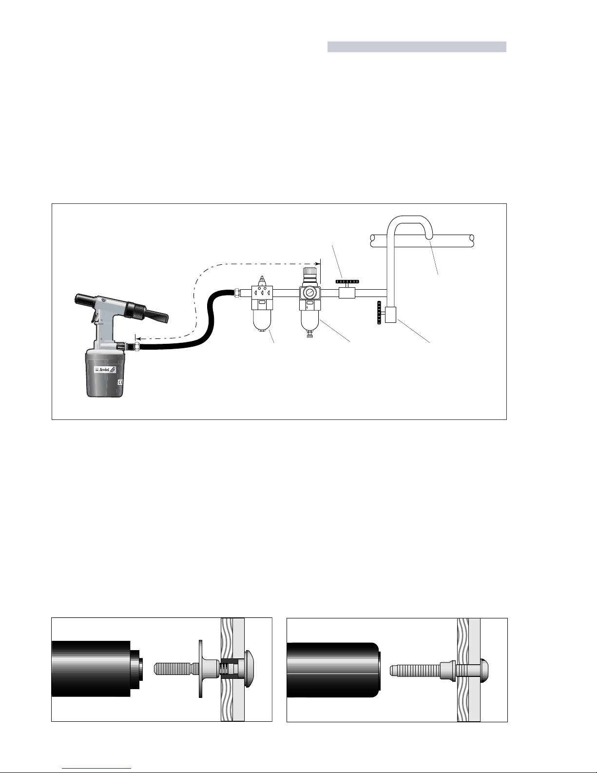
All tools are operated with compressed air at an optimum pressure of 5.4 bar. We recommend the use of pressure regulators and
automatic oiling/filtering systems on the main air supply. These should be fitted within 3 metres of the tool (see diagram bel ow) to ensure
maximum tool life and minimum tool maintenance.
Air supply hoses should have a minimum working effective pressure rating of 150% of the maximum pressure produced in the system
or 10 bar, whichever is the highest. Air hoses should be oil resistant, have an abrasion resistant exterior and should be armou red where
operating conditions may result in hoses being damaged. All air hoses MUST have a minimum bore diameter of 6.4 millimetres or
1
/
4
inch.
Read servicing daily details page 10.
8
6
4
2
0
0
1
2
1
41
6
1
TAKE OFF POINT
FROM MAIN SUPPLY
STOP COCK
(USED DURING MAINTENANCE
OF FILTER/REGULATOR OR LUBRICATION UNITS)
MAIN SUPPLY
DRAIN POINT
PRESSURE REGULATOR
AND FILTER
(DRAIN DAILY)
LUBRICATOR
3
M
E
T
R
E
S
M
A
X
I
M
U
M
O P E R A T I N G P R O C E D U R E
07611 model for AVTAINER
■ Ensure that the correct nose assembly is fitted.
■ Connect the tool to the air supply.
■ Push the Avtainer through the prepared hole in the application.
■ Slide the collar over the stem (orientation as shown below).
■ Keeping the head of the Avtainer against the application, place the
nose assembly of the tool over the protruding stem.
■ Fully operate the trigger. One cycle will ensure that the collar is
forced over the lock grooves of the stem and that the stem breaks
at the breaker groove.
■ Release the trigger. The tool completes its cycle by pushing itself off
the collar and ejecting the spent stem at the rear.
07613 model for MAXLOK
■ Ensure that the correct nose assembly is fitted.
■ Connect the tool to the air supply.
■ Push the Maxlok stem through the application hole .
■ Place the collar on the stem (orientation as shown below).
■ Keeping the head of the stem against the application, push the tool
onto the protruding stem.
■ Fully depress the trigger. One cycle will ensure that the collar is
swaged into the lock grooves of the stem and the the stem breaks
at the breaker groove.
■ Release the trigger. The tool completes its cycle by pushing itself off
the collar and ejecting the spent stem at the rear.
7
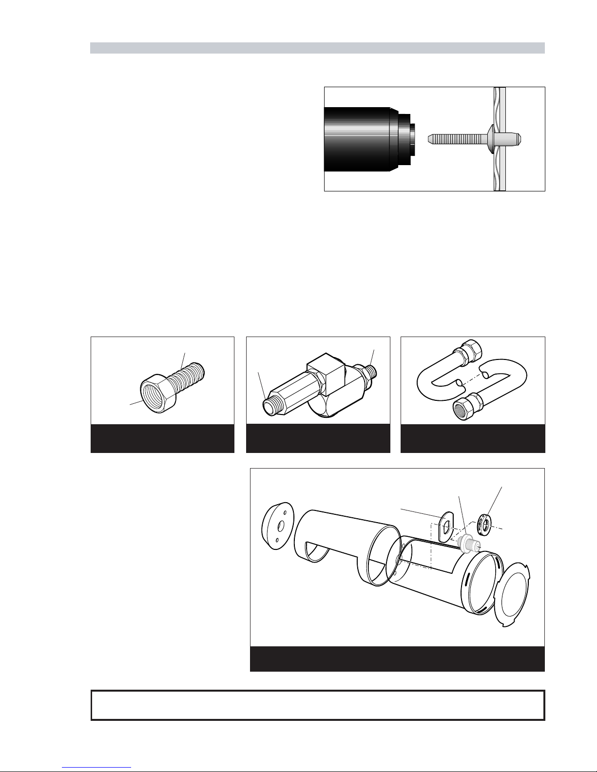
TO FIT 6.4 mm (1/4”) BORE PIPE
L = 137 cm
1/4” BSP
HOSE CONNECTOR
part nº 07005-00276
HOSE ASSSEMBLY
part nº 07008-00324
1/4” BSP
1/4” BSP
SWIVEL CONNECTOR
part nº 07640-01400
A C C E S S O R I E S
Three different accessories are available to make the connection to your air supply:
FOR 07611 MODEL
part nº 07611-00400
FOR 07613/4 MODELS
part nº 07498-03700
I M P O R T A N T
The stem collector MUST be emptied frequently, approximately when half full or every 120 placings.
OPTION 2
■ Ensure that the correct nose equipment is fitted.
■ Connect the tool to the air supply.
■ Insert the fastener stem into the nose of the tool.
■ Insert the tool with the fastener squarely into the prepared hole of the
application.
■ Fully operate the trigger. The tool cycle will ensure the fastener is
placed.
Approximate dimensions of assembled unit are:
Length: 107mm (4.2”)
Diameter: 63.5mm (2.5”)
ADAPTOR
(ON 07611 MODEL)
LOCKING RING
CLAMP WASHER
STEM COLLECTOR
To better control waste, a stem collector
can be fitted as an alternative to the stand-
ard stem deflector.
■ To fit the stem collector, unscrew the end
cap and remove together with the stem
deflector(items9and10ofpage 14 to 17).
■ Assemble the stem collector as shown on
the drawing opposite.
■ Push the assembly onto the cylinder end
plug (item 11 of page 14 to 17).
■ Secure by finger tightening thepreviously
removed adaptor on the 07611 model or
the locking ring supplied for the 07613
and 07614 models over the clamp
washer.
■ Rotate the stem collector body until the
opening is in the desired position.
■ Fully tighten the adaptor or locking ring.
07614 model for HEMLOK
When placing Hemlok, two different approaches may be used, both
resulting in equal quality placing. OPTION 1 brings the tool to the
fastener already positioned in the application hole while OPTION 2
positions the fastener in the tool, or specifically in its nose assembly,
then brings them together to the application.
Use which ever suits your environment and application.
OPTION 1
■ Ensure that the correct nose equipment is fitted.
■Connect the tool to the air supply.
■ Insert the fastener body squarely into the prepared hole of the
application as shown right.
■ Apply the tool to the protruding fastener stem.
■ Fully operate the trigger. The tool cycle will ensure the fastener is
placed.
8
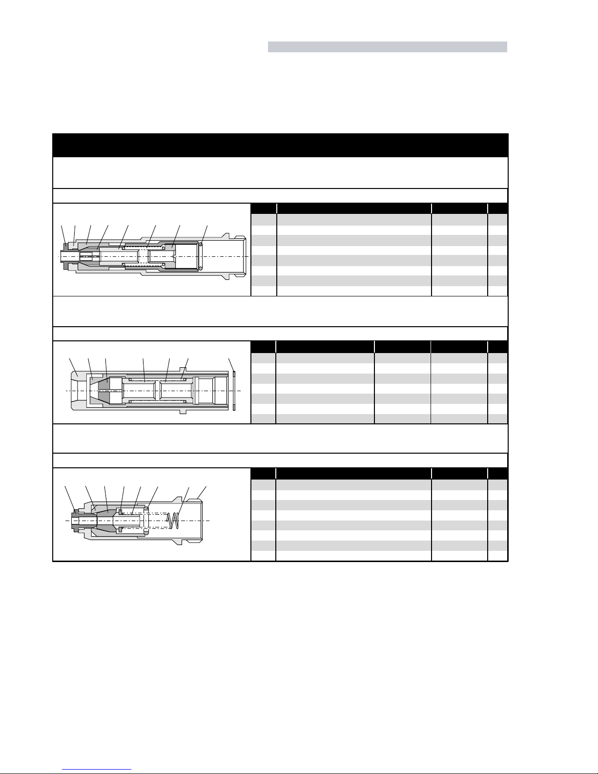
NO S E A S S E M B L I E S
If you have purchased a complete tool, it will already be fitted with the correct nose assembly for your fastener. It is essent ial that the correct nose
assembly is fitted prior to operating the tool. By knowing your original complete tool part number or the details of the fasten er to be placed, you can
order a complete new nose assembly using the selection table page 4 or you can order individual components using the tables bel ow.
1
2
3
5
6
9
10
11
1
1
1
1 SET
1
1
1
1
07498-00802
07498-00501
07498-00801
07220-02302
07498-00803
07500-02005
07498-00503
07340-00327
NOSE TIP
NOSE CASING
CHUCK COLLET
JAWS
FRONT SPRING GUIDE
SPRING
REAR SPRING GUIDE
LOCKING RING
ITEM COMPONENT PART Nº QTY
AVTAINER nose assembly 07498-00800
COMPONENT PART NUMBERS
1 2 3 5 6 9 10 11
12 3 5 9610 11 12
3
5
6
9
10
11
1
1
1 SET
2
1
1
1
07610-02001
07610-02002
07610-02003
07220-02104
07610-02107
07610-02004
07220-02104
07610-02101
07610-02102
07610-02103
07220-02104
07610-02107
07610-02004
07220-02104
ANVIL
CHUCK COLLET
JAWS
FRONT SPRING GUIDE
SPRING
REAR SPRING GUIDE
LOCKING RING
ITEM COMPONENT 3/16" 1/4" QTY
MAXLOK nose assemblies 07610-02000 & 07610-02100
1
2
4
5
7
8
9
11
1
1
1
1 SET
1
1
1
1
07612-02001
07340-00306
07612-02003
07612-02002
07498-04502
07498-03003
07500-00418
07340-00327
NOSE TIP
NOSE CASING
JAW HOUSING
JAWS
JAW SPREADER
BUFFER
SPRING
LOCKING RING
ITEM COMPONENT PART Nº QTY
HEMLOK nose assembly 07612-02000
145 781192

9
FITTING INSTRUCTIONS
I M P O R T A N T
The air supply must be disconnected when fitting or removing nose assemblies unless specifically instructed otherwise.
These instructions apply toall three models. Simply ignore instructions relating to items that do not exist in your particular nose assembly.
■ Lightly coat jaws 5with Moly lithium grease.
■ Drop jaws 5into jaw housing 4or chuck collet 3.
■ Insert jaw spreader 7into jaw housing 4(locating in the ‘V’ shape formed by the jaws) or insert front spring guide 6into chuck collet 3.
■ Locate buffer 8on jaw spreader 7.
■ Locate spring 9onto jaw spreader 7or onto front spring guide 6.
■ Screw or drop rear spring guide 10 into chuck collet 3.
■ Fit locking ring 11 onto the jaw spreader housing of the tool, item 24 pages 14 to 17.
■ Holding tool pointing down, screw the assembled jaw housing or chuck collet onto the jaw spreader housing and tighten with span ner.
■ Screw nose tip 1into nose casing 2.
■ Place nose casing 2over jaw housing 4and screw onto tool, tightening with spanner or place anvil 12 over chuck collet3and lock into place with
the anvil nut, item 25 page 16 and 17.
SERVICING INSTRUCTIONS
Nose assemblies should be serviced at weekly intervals.
■ Remove the complete nose assembly using the reverse procedure to the ‘Fitting instructions’.
■ Any worn or damaged part should be replaced.
■ Particularly check wear on jaws.
■ Check spring 9is not distorted.
■ Assemble according to fitting instructions.

10
SE R V I C I N G T H E T O O L
FIRST AID
SKIN: As the grease is completely water resistant it is best
removed with an approved emulsifying skin cleaner.
INGESTION: Make the individual drink 30ml Milk of
Magnesia, preferably in a cup of milk.
EYES: Irritant but not harmful. Irrigate with water and
seek medical attention.
ENVIRONMENT
Scrape up for burning or disposal on approved site.
M O L Y L I T H I U M G R E A S E E P 3 7 5 3 S A F E T Y D A T A
FIRE
FLASH POINT: Above 220°C.
Not classified as flammable.
Suitable extinguishing media: CO 2, Halon or water spray
if applied by an experienced operator.
HANDLING
Use barrier cream or oil resistant gloves
STORAGE
Away from heat and oxidising agent.
Grease can be ordered as a single item, the part number is shown in the service kit opposite.
Regular servicing should be carried out and a comprehensive inspection performed annually or every 500000 cycles, whichever is
sooner.
I M P O R T A N T
The employer is responsible for ensuring that tool maintenance instructions are given to the appropriate personnel. The operator should
not be involved in maintenance or repair of the tool unless properly trained.
D A I L Y
■Daily, before use or when first putting the tool into service, pour a few drops of clean, light lubricating oil into the air in let of the
tool if no lubricator is fitted on air supply. If the tool is in continuous use, the air hose should be disconnected from the m ain air
supply and the tool lubricated every two to three hours.
■Check for air leaks. If damaged, hoses and couplings should be replaced.
■If there is no filter on the pressure regulator, bleed the air line to clear it of accumulated dirt or water before connecting air hose
to tool. If there is a filter, drain it.
■Check that the nose equipment is correct.
■Ensure either a stem collecter or a spent stem deflector is fitted to the tool.
■Check the stroke of the tool meets the minimum specification (inside front page). It is the difference in the measurement between
the front face of the jaw spreader housing assembly and the front face of the head before pressing the trigger and when it is fully
depressed.
W E E K L Y
■Dismantle and clean the nose assembly with special attention to the jaws. Lubricate with Moly Lithium grease before assembling.
■Check for oil leaks and air leaks in the air supply hose and fittings.

11
For all servicing we recommend the use of the service kit below, part number 07900-04990.
NOTE: Spanner sizes are measured ‘across flats’ unless otherwise specified.
T O T A L M A I N T E N A N C E
Every 500,000 cycles the tool should be completely dismantled and new components should be used where worn, damaged or when
recommended. All ‘O’ rings and seals should be renewed and lubricated with Moly Lithium grease EP 3753 before assembling.
I M P O R T A N T
Safety Instructions appear on pages 2 & 3.
The employer is responsible for ensuring that tool maintenance instructions are given to the appropriate personnel.
The operator should not be involved in maintenance or repair of the tool unless properly trained.
The airline must be disconnected before any servicing or dismantling is attempted, unless specifically instructed otherwise.
It is recommended that any dismantling operation be carried out in clean conditions.
Item numbers in bold refer to the general assembly drawing and parts list pages 14 to17.
Before proceeding with dismantling, remove screw 22 and seal 56 and empty oil from the tool into a suitable container.
Prior to dismantling the tool it is necessary to remove the nose assembly. For simple removal instructions see the nose assemblies ‘Fitting
Instructions’ page 9.
For total tool servicing we advise that you proceed with dismantling of sub-assemblies in the order shown pages 12 and 13.
PART Nº DESCRIPTION QTYPART Nº DESCRIPTION QTY
SERVICE KIT
07001-00092 SCREW 6
07900-00001 SPRING COMPRESSION TOOL 1
07900-00006 'O' RING ASSEMBLING TOOL 1
07900-00008
7
/
16
" x
1
/
2
" SPANNER 1
07900-00009
3
/
32
" ALLEN KEY 1
07900-00012
9
/
16
" x
5
/
8
" ALLEN KEY 1
07900-00013
1
/
8
" ALLEN KEY 1
07900-00015
5
/
8
" x
11
/
16
" SPANNER 1
07900-00078
5
/
32
" ALLEN KEY 1
07900-00137 TOMMY BAR 1
07900-00429 SPANNER ASSEMBLY FOR HEAD PISTON 1
07900-00158 PIN PUNCH 1
07900-00159
7
/
16
" x
1
/
2
"SPANNER 1
07900-00160 NOSE BULLET 1
07900-00164 CIRCLIP PLIERS 1
07900-00163
5
/
64
" ALLEN KEY 1
07900-00004 RIGHT ANGLE CIRCLIP PLIERS 1
07900-00249 PRIMING PUMP ASSEMBLY 1
07900-00252 SEAL EXTRACTOR 1
07900-00382 SCREWDRIVER 1
07900-00421
13
/
16
" RING SPANNER 1
07900-00432 PLASTIC CASE 1
07992-00020 80 g
TIN MOLYLITHIUM GREASE EP 3753 1
07900-00539 SPANNER 1
07900-00540 SPANNER 1
03201-00615 PIN 1
07900-00236
SPANNER 1
07900-00628 HEAD PISTON ROD SEAL ENTRY GUIDE 1
07900-00629 HEAD PISTON ROD INSTALLATION TOOL 1
07900-00630 PISTON SEAL ENTRY GUIDE 1

12
* refers to items included in the Avdel service kit. For complete list see page 11.
HYDRAULIC PISTON ASSEMBLY
■ Remove stem deflector10 and end cap 9.
■ On 07611 model, remove adaptor 15 using spanner* and washer 16 .
■ On 07613 model only, unscrew anvil adaptor 26 and anvil nut 25 .
■ With spring compressor tool* held in vice, compress spring 6, applying clamp screw ball-end to cylinder end plug 11 .
■ Using right angle circlip pliers* remove internal circlip or collar 8.
■ Unscrew the compression tool and remove cylinder end plug 11 and spring 6.
■ Unscrew jaw spreader housing assembly 24 or 24b with spanner* and special spanner assembly*, then withdraw hydraulic piston 5.
■ On 07611 model, remove piston stop 21 and using circlip pliers* remove head piston stop 3and lip seal 2.
■ On 07613/4 models remove head retaining plate 3.
■ Using circlip pliers* remove internal circlip 39 .
■ Remove lip seal 2and wiper ring 23 .
■ Remove piston seal/lip seal 4from piston 5.
■ Before assembling inspect the piston diameters and the cylinder bore for wear and damage.
■ Insert the head piston rod seal entry guide* into the hydraulic bore.
■ With lip seal 2on the rod seal installation tool* push the seal into its housing with the lip of the seal towards the back of the tool.
■ Remove the installation tool and seal entry guide and confirm that the seal is properly seated in its housing.
■ On 07611 model, replace head piston stop 3using circlip pliers*.
■ On 07613 & 07614 models, fit circlip 39 using circlip pliers*. Replace the head retaining plate 3inside bore.
■ Screw nose bullet* onto end of piston rod.
■ Insert piston seal entry guide* into the hydraulic bore.
■ Ensuring correct orientation, position piston/lip seal 4onto hydraulic piston 5and insert the piston into the hydraulic bore.
■ Remove nose bullet*.
■ On 07611 model, fit head piston stop 3.
■ Fit new wiper ring 23 .
■ Always screw on a new jaw spreader housing and tighten to achieve a maximum gap of 8.5 millimetres (0.335 inches) between its rear face
and the front face of the head and handle assembly 1.
■ Discard old jaw spreader housing.
■ Complete assembly in reverse order to dismantling.
PNEUMATIC PISTON ASSEMBLY
■ Remove bleed screws 22 and 41 from head and handle assembly 1and drain oil into a suitable container.
■ With the tool connected to the air supply, depress the trigger and remove the tool from the air supply.
■ Remove connector54 , washer 55 and silencer 28 .
■ Actuate the trigger several times.
■ UsingAllen key*,remove screws 48 , ONEAT ATIME, and installthe servicescrews*. The orderof screwremoval
and replacement i is important and must follow the sequence shown in the diagram (right).
■ Withdraw head and handle assembly 1to full extent of service screws.
■ Check pneumatic piston assembly 42 is at top of pneumatic cylinder 50 before finally dismantling.
■ Remove the six service screws and withdraw head and handle assembly 1and air piston assembly 42 from air
cylinder 50 .
■ Remove ‘O’ ring 52 from air piston assembly 42 .
■ Remove gasket 47 .
■ Using Allen key*, remove eight screws 17 securing retaining plate 18 .
■ Using seal extractor*, withdraw seal housing 14 .
1
35
2
4
6
TIGHTENING
SEQUENCE

13
* refers to items included in the Avdel service kit. For complete list see page 11.
I M P O R T A N T
Check the tool against daily and weekly servicing.
Priming is ALWAYS necessary after the tool has been dismantled and prior to operating.
■ To replace ‘O’ ring 52 use ‘O’ ring assembling tool*.
■ Inspect intensifier rod 43 and buffers 45 & 51 . If damaged replace using tommy bar* and kit spanner assembly for head piston*.
■ Lubricate bores with Moly Lithium grease EP 3753*.
■ Insert seal housing 14 into head and handle sub-assembly 12 with ‘O’ rings 13 .
■ Attach the retaining plate with the eight screws tightened to a torque of 30 lb/in (3.39 Nm).
■ Insert intensifier rod through the seal housing into the handle assembly.
■ Fit new gasket 47 .
■ If nut 46 is removed, it MUST be replaced by a new one.
■ Assemble handle to air cylinder and complete assembly in reverse order to dismantling.
AIR VALVE ASSEMBLY
■ Remove plastic handle covers 57 and 59 using Allen key* to release screws 58 .
■ Unscrew end plug 29 , remove spring 30 and withdraw valve spool 31 .
■ Using Allen key*, remove screws 36 securing silencer retainer 34 and withdraw silencer 28 .
■ Clean all parts particularly silencer and bush 33 .
■ Complete assembly in reverse order to dismantling.
TRIGGER ASSEMBLY
■ Remove plastic handle covers 57 and 59 using Allen key*.
■ Using Allen key*, remove two screws 36 releasing crank pin retainer 37 , crank pin pivot 38 , silencer retainer 34 and crank pin 35 .
■ Knock out pin 20 using pin punch*.
■ Remove trigger assembly 19 from head and handle assembly 1.
■ Complete assembly in reverse order to dismantling.
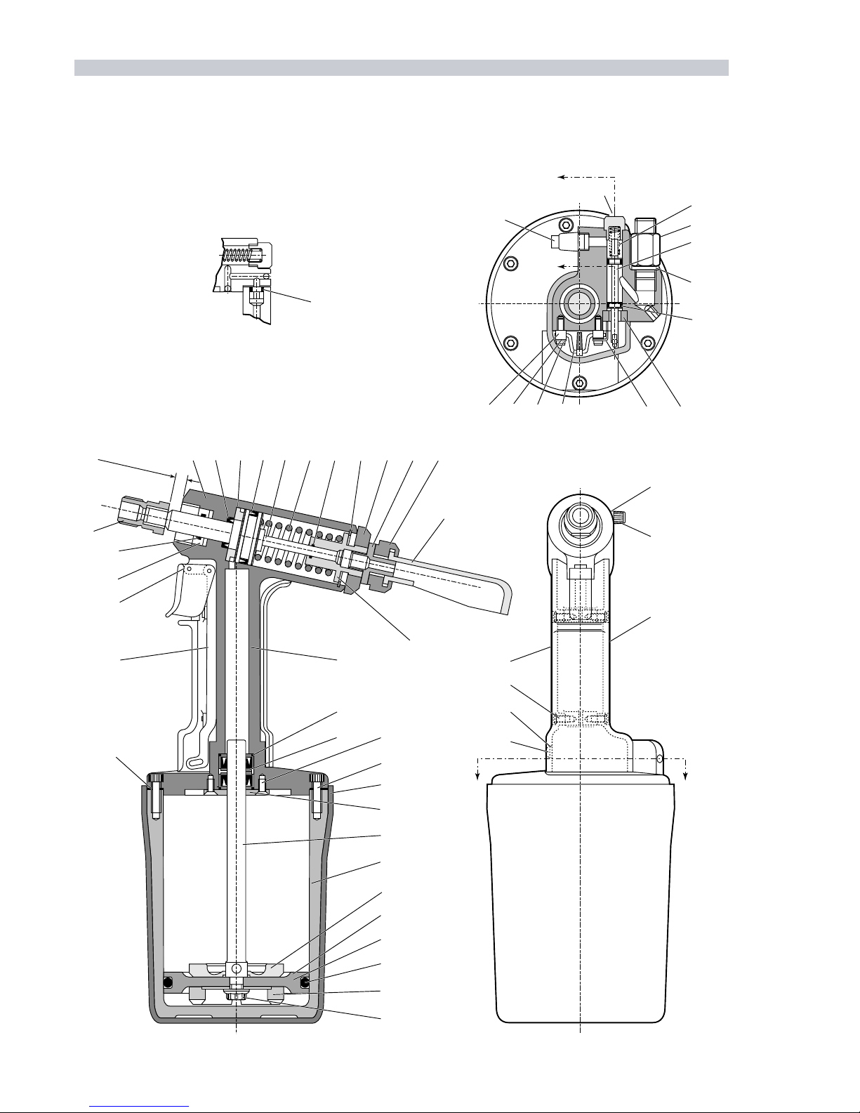
14
GENERAL ASSEMBLY OF BASE TOOL 07611-00200
24
xammm5.8
xam"533.
21
20
11
12
13
14 17
49
47 48
18
43
50
51
42
52
45
46
10
23
1 2 3 4 5 6 7 8 16 15 9
A-A
B-B
19
44
30
54
31
55
32
34 33
353738 36
28
29
41
40
58
59
57
56
22
BB
A
A
53

15
07611-00200 PARTS LIST- Spares are minimum recommended levels
ITEM
PART Nº DESCRIPTION QTY
SPARES
1 07611-00500 HEAD & HANDLE ASSEMBLY 1 -
2 07003-00245
●
LIP SEAL 1-
3 07498-02302
●
HEAD PISTON STOP 1 -
4 07003-00244
●
LIP SEAL 1-
5 07611-00501
●
HYDRAULIC PISTON 1 -
6 07490-03002
●
SPRING 1-
7 07003-00030
●
'O' RING 13
8 07004-00022
●
CIRCLIP 11
9 07340-00332
●
END CAP 11
10 07340-00342
●
STEM DEFLECTOR 1 1
11 07610-00305
●
CYLINDER END PLUG 1 -
12 07498-02800
●
HEAD & HANDLE 1 -
13 07003-00100
●
'O' RING 24
14 07498-02200
●
SEAL HOUSING 1-
15 07611-00301
●
ADAPTOR 1-
16 07498-00204
●
WASHER 11
17 07001-00339
●
SCREW 88
18 07498-00301
●
RETAINING PLATE 1 2
19 07490-00600
●
TRIGGER ASSEMBLY 1 2
20 07007-00301
●
PIN 1-
21 07498-02304
●
PISTON STOP 11
22 07498-00206
●
SCREW 1-
23 07003-00156
●
WIPER RING 14
24 07490-00700
●
JAW SPREADER HOUSING 1 -
28 07007-00311
●
SILENCER 1-
29 07490-03506
●
END PLUG 1-
30 07340-01303
●
SPRING 12
31 07490-03507
●
VALVE SPOOL 1-
32 07003-00001
●
'O' RING 24
33 07490-03800
●
SILENCER & BUSH 1 -
34 07490-03501
●
SILENCER RETAINER 1 -
35 07490-03503
●
CRANK PIN 1-
36 07001-00109
●
SCREW 22
37 07490-03504
●
CRANK PIN RETAINER 2 -
38 07490-03502
●
CRANK PIN PIVOT 2 2
40 07003-00033
●
SEAL 25
41 07001-00114
●
SCREW 12
42 07498-02900 PNEUMATIC PISTON ASSEMBLY 1 -
43 07498-02901
●
INTENSIFIER ROD 1 1
44 07490-03601
●
PISTON 1-
45 07490-03104
●
PISTON BUFFER (BOTTOM) 1 -
46 07002-00017
●
NUT 1 2
47 07490-00209 GASKET 12
48 07001-00108 SCREW 66
49 07611-00201 CYLINDER SLEEVE 11
50 07498-00600 PNEUMATIC CYLINDER 1 -
51 07490-00201 PISTON BUFFER (TOP) 1 -
52 07003-00131 'O' RING 14
53 07003-00029 'O' RING 14
54 07490-02201 CONNECTOR 11
55 07005-00015 WASHER 11
56 07003-00033 SEAL 15
57 07490-00206 HANDLE COVER-LEFT 1 -
58 07001-00130 SCREW 44
59 07490-00205 HANDLE COVER-RIGHT 1 -
60 07900-00437 INSTRUCTION MANUAL 1 1
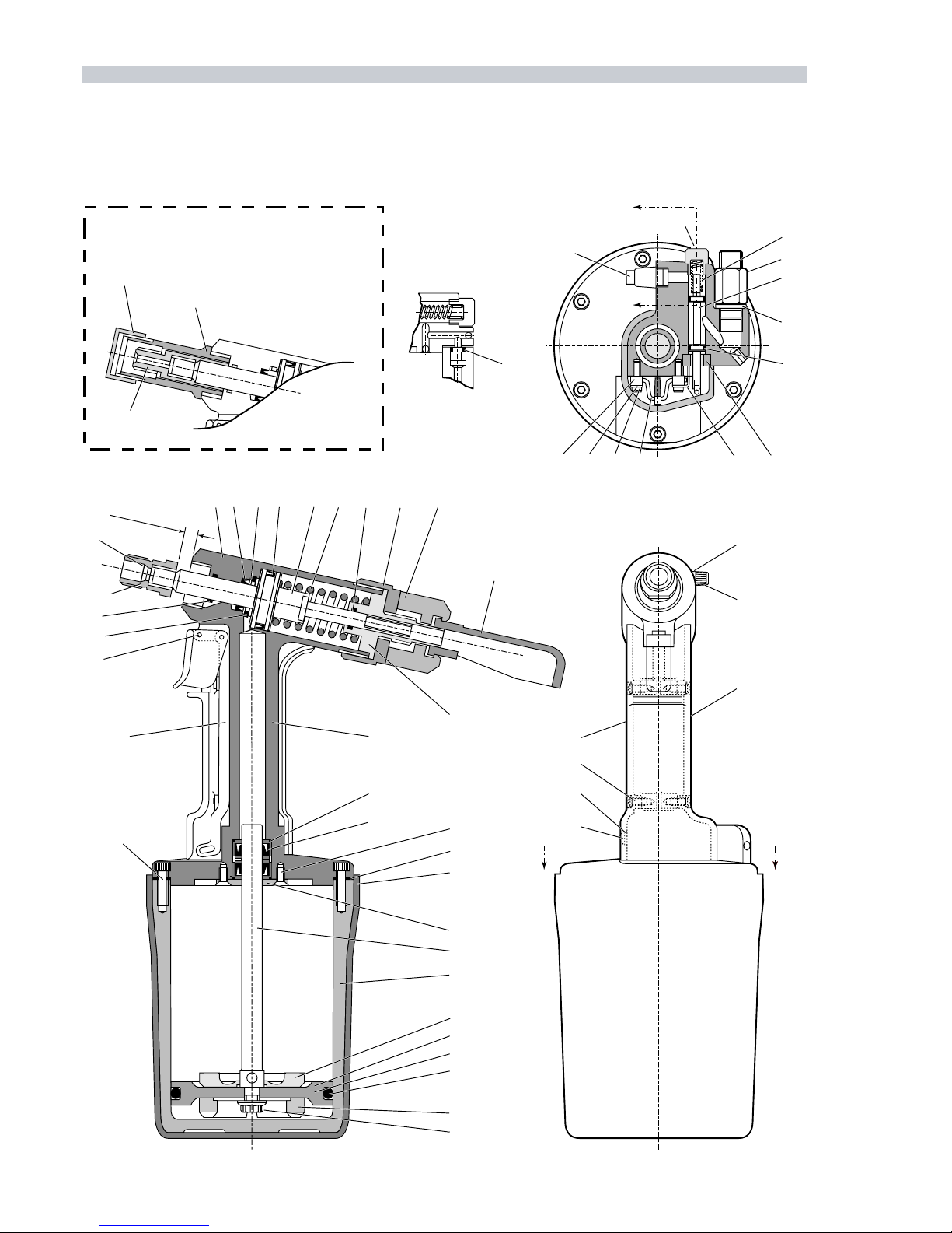
16
GENERAL ASSEMBLY OF BASE TOOL 07613-00200 & 07614-00200
07613-00200 ONLY
27
24
39
20
11
12
13
14 17
49
48
47
18
43
50
51
44
52
45
46
10
23
1234 5 6 7 8 9
A-A
B-B
19
42
30
54
31
55
32
34 33
353738 36
28
A
29
A
53
26
25
24 b
41
40
58
59
57
56
22
BB
.
xammm5.8
..xam"
533

17
07613-00200 AND 07614-00200 PARTS LIST- Spares are minimum recommended levels
ITEM
PART Nº DESCRIPTION QTY
SPARES
1 07613-00700 HEAD & HANDLE ASSEMBLY 1 -
2 07003-00245
●
LIP SEAL 1-
3 07490-00316
●
HEAD RETAINING PLATE 1 -
4 07003-00262
●
LIP SEAL 1-
5 07613-00305
●
HYDRAULIC PISTON 1 -
6 07490-03002
●
SPRING 11
7 07003-00030
●
'O' RING 12
8 07613-00303
●
COLLAR 11
9 07498-00313
●
END CAP 1-
10 07340-00342
●
STEM DEFLECTOR 1 2
11 07613-00302
●
CYLINDER END PLUG 1 -
12 07613-00600
●
HEAD & HANDLE 1 -
13 07003-00100
●
'O' RING 2-
14 07498-02200
●
SEAL HOUSING 1-
17 07001-00339
●
SCREW 8-
18 07498-00301
●
RETAINING PLATE 1 -
19 07490-00600
●
TRIGGER ASSEMBLY 1 -
20 07007-00301
●
TRIGGER PIN 12
22 07498-00206
●
SCREW 1-
23 07003-00156
●
WIPER RING 12
24 07490-00700
●
JAW SPREADER HOUSING 1 -
24b 07610-00500
●
JAW SPREADER HOUSING 1 -
25 07610-00307
●
ANVIL NUT 1-
26 07610-00303
●
ANVIL ADAPTOR 1 -
27 07614-00201
●
GUIDE TUBE 11
28 07007-00311
●
SILENCER 11
29 07490-03506
●
END PLUG 11
30 07340-01303
●
SPRING 11
31 07490-03507
●
VALVE SPOOL 1-
32 07003-00001
●
'O' RING 24
33 07490-03800
●
SILENCER & BUSH 1 -
34 07490-03501
●
SILENCER RETAINER 1 -
35 07490-03503
●
CRANK PIN 11
36 07001-00109
●
SCREW 24
37 07490-03504
●
CRANK PIN RETAINER 2 -
38 07490-03502
●
CRANK PIN PIVOT 2 2
39 07004-00033
●
CIRCLIP 11
40 07003-00033
●
SEAL 13
41 07001-00114
●
SCREW 12
42 07498-02900 PNEUMATIC PISTON ASSEMBLY 1 1
43 07498-02901
●
INTENSIFIER ROD 1 1
44 07490-03601
●
PISTON 11
45 07490-03104
●
PISTON BUFFER (BOTTOM) 1 1
46 07002-00017
●
NUT 12
47 07490-00209 GASKET 11
48 07001-00108 SCREW 64
49 07611-00201 CYLINDER SLEEVE 1-
50 07498-00600 PNEUMATIC CYLINDER 1 -
51 07490-00201 PISTON BUFFER (TOP) 1 -
52 07003-00131 'O' RING 14
53 07003-00029 'O' RING 14
54 07490-02201 CONNECTOR 11
55 07005-00015 WASHER 11
56 07003-00033 SEAL 13
57 07490-00206 HANDLE COVER-LEFT 1 -
58 07001-00130 SCREW 44
59 07490-00205 HANDLE COVER-RIGHT 1 -
60 07900-00437 INSTRUCTION MANUAL 1 1

ENVIRONMENT
WASTE DISPOSAL: Through authorised contractor to a
licenced site. May be incinerated.
Used product may be sent for reclamation.
SPILLAGE: Prevent entry into drains, sewers and water courses.
Soak up with absorbent material.
HANDLING
Wear eye protection, impervious gloves (e.g. of PVC) and a
plastic apron. Use in well ventilated area.
STORAGE
No special precautions.
PROPERTIES RESULT
Foaming tendency/stability
ml @ 24°C Trace/Nil
ml @ 93.5°C 20/Nil
ml @ 24°C after test @ 93.5°C Trace/Nil
Air release value minutes to
0.2% air content @ 50°C 4
Seal compatibility index 10
Water separation time
in minutes to 40-40-0 @54°C 15
@83°C 15
P R O C E D U R E
I M P O R T A N T
All operations should be carried out on a clean bench, with clean hands in a clean area.
Ensure that the priming pump is free from foreign matter and that the oil is perfectly clean and free from air bubbles.
Care MUST be taken at all times, to ensure that no foreign matter enters the tool, or serious damage may result.
Item numbers in bold refer to the general assembly and parts list pages 14 to 17.
■Clean the exterior of the tool and stand on clean bench.
■Disconnect the air supply.
■Fill the priming pump supplied with every complete tool or available in the service kit, with priming oil. Expel any air by applying pressure
to the end of the pump or ‘actuating’ the pump. Spare threaded nipples are available part number 07900-00250.
■Remove filler screw 41 and seal 40 at the base of the handle and bleed screw 22 and seal 56 on the side of the head.
■Screw the priming pump into the hole left by screw 41.
■Actuate the priming pump several times until the air coming out of the bleed screw hole is free of air bubbles.
■Replace seal 56 and bleed screw 22.
■Lay the tool horizontally with the priming pump uppermost. Remove the priming pump.
■Replace seal 40 and filler screw 41 .
■Reconnect the air supply and check that the stroke of the tool is within specification. If not, repeat priming procedure.
18
Priming is ALWAYS necessary after the tool has been dismantled and prior to operating. It may also be necessary to restore the full
stroke after considerable use, when the stroke may be reduced and fasteners are not fully placed by one operation of the trigger.
O I L D E T A I L S
The recommended oil for priming is Hyspin VG32 available in 0.5l (part number 07992-00002) or one gallon containers (part number
07992-00006). Please find specific table and safety data below.
PR I M I N G
FIRST AID
SKIN: Wash thoroughly with soap and water as soon as
possible. Casual contact requires no immediate attention.
Short term contact requires no immediate attention.
INGESTION: Seek medical attention immediately.
DO NOT induce vomiting.
EYES: Irrigate immediately with water for several minutes.
Although NOT a primary irritant, minor irritation may occur
following contact.
FIRE
Suitable extinguishing media: CO2, dry powder, foam or
water fog. DO NOT use water jets.
PROPERTIES RESULT
ISO oil type HL
ISO viscosity grade 32
Kinematic viscosity
cS @ 40°C 32
@ 100°C 5.3
Relative density at 20°C 0.875
Viscosity Index 95
Pour point °C - 30
Open Flash point °C 232
Neutralisation value mg KOH/g 1.5
H Y S P I N V G 32 O I L S A F E T Y D A T A
This manual suits for next models
2
Table of contents
Other Avdel Power Tools manuals

Avdel
Avdel T51 User manual

Avdel
Avdel Genesis G2LB User manual

Avdel
Avdel Genesis G2LB User manual

Avdel
Avdel eRiv User manual

Avdel
Avdel 73414-02000 User manual

Avdel
Avdel G3LB Tool User manual

Avdel
Avdel Genesis G2LB User manual

Avdel
Avdel 7265 User manual

Avdel
Avdel 73435-02000 User manual

Avdel
Avdel Genesis G1 71204 User manual


Popular Power Tools manuals by other brands

Easylife
Easylife EL2636 instruction manual

Columbus McKinnon
Columbus McKinnon Tigrip TWH operating instructions

MasterCraft
MasterCraft 54-4892-4 instruction manual

MK Diamond Products
MK Diamond Products MK 770 owner's manual

Grizzly
Grizzly G8994Z owner's manual

Weller
Weller WHA 3000P operating instructions


