manuals.online logo
Brands
  1. Home
  2. •
  3. Brands
  4. •
  5. AVYCON
  6. •
  7. Security Camera
  8. •
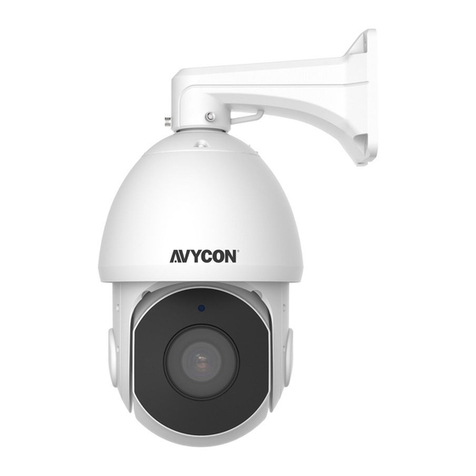
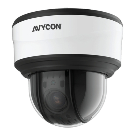
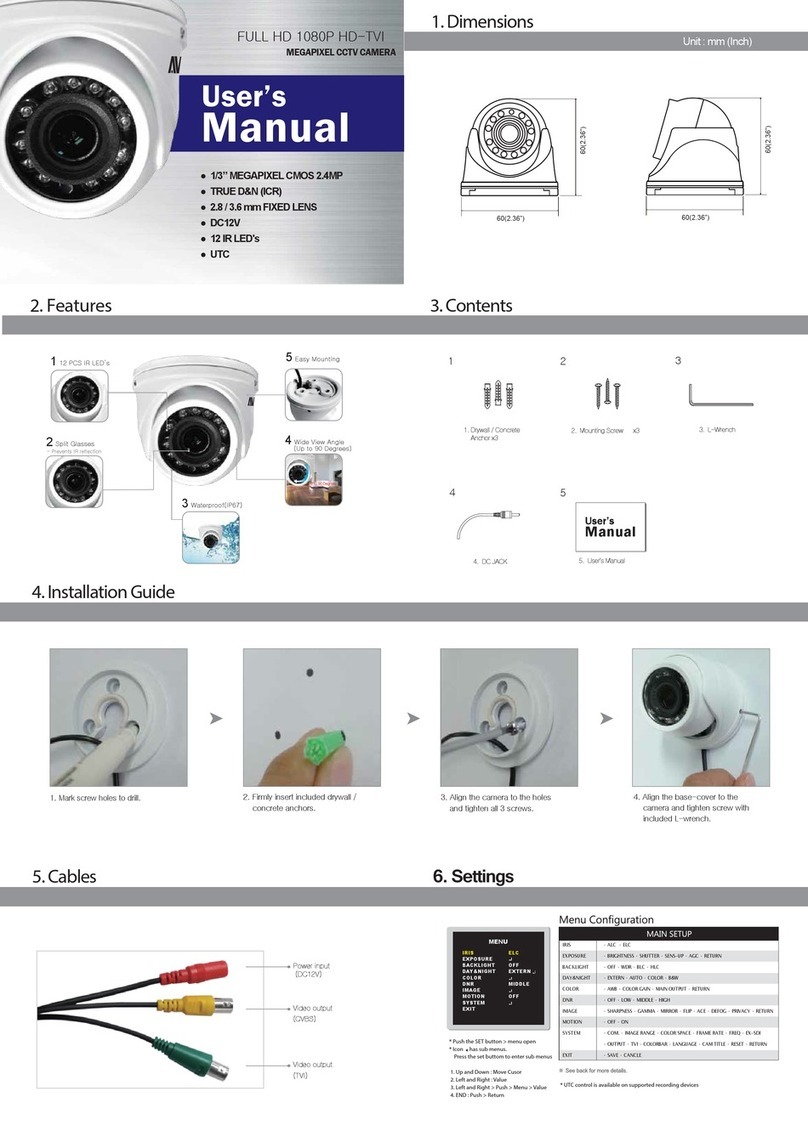
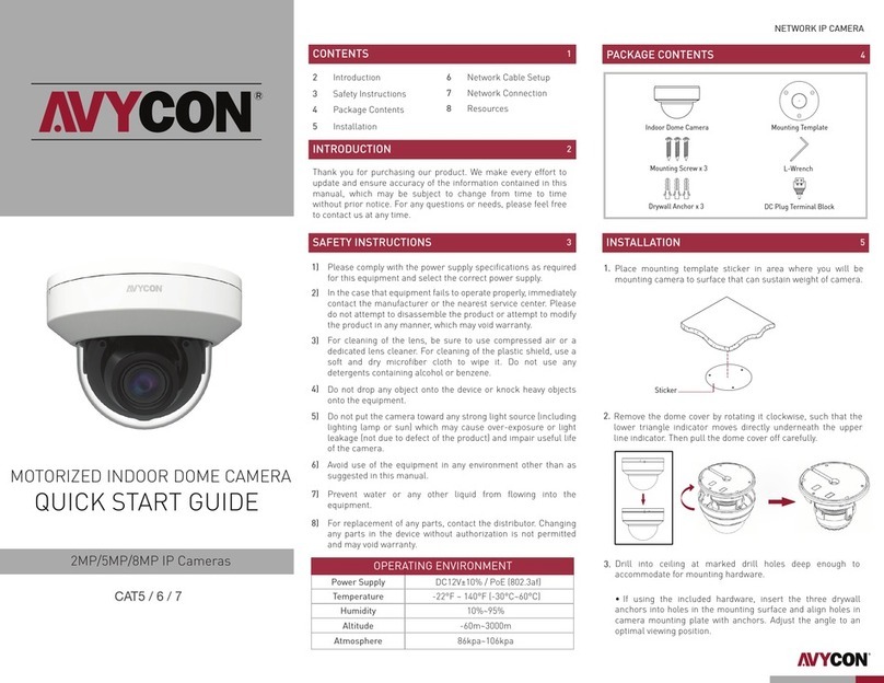
  9. AVYCON AVC-NBM81F180 User manual

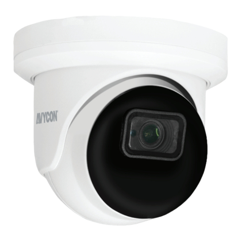
AVYCON AVC-NBM81F180 User manual

• If the product does not work properly, please contact your dealer or the
nearest service center. Never attempt to disassemble the camera yourself.
(We shall not be responsible for any problems caused by unauthorized
repair or maintenance.)
• Keep product away from liquid while in use.
• In the use of the product, you must be in strict compliance with the
electrical code of your county or state.
• When mounting the camera on a wall or ceiling, please ensure that it is
properly mounted with the correct hardware.
• Do not use camera beyond specified voltage range.
• Do not drop the camera or subject it to physical shock.
• Avoid touching the camera lens.
• If cleaning is necessary, please use a clean cloth to wipe it gently. If the
device will not be used for a long time, please cover the lens cap to
protect the device from dirt.
• Do not aim the camera directly at the sun or a very bright light source.
• Do not place the camera in extremely hot, cold (operating temperature
should be -30˚C~ 60˚C), dusty or damp locations, and do not expose it to
high electromagnetic radiation.
• To avoid overheating, decent ventilation for the product is required in the
operating environment.
• Some parts connected to device may need to be replaced regularly due
to environmental conditions or the lifespan of these parts. Regular
maintenance checks are recommended for all users.
1. WARNING AND CAUTION
2. PACKAGE
3. OVERVIEW
4. INSTALLATION
ALARM CONNECTION
CONNECTING NETWORK CABLE
NETWORK CAMERA
QUICK START GUIDE
Thank you for purchasing our product. There may be some outdated information or printing
errors in this manual. The updates are continually added into the newest version of this manual.
We will readily update the products or procedures described in the manual. The contents are
subject to change without notice.
Camera Quick Start Guide Mounting Screw x 4
CD Mounting Template Drywall Anchor x 4
Rubber Plug Wrench
Alarm Input: Join the grounding ends of the sensor and the camera and
then connect the signal cable of the sensor to the alarm input port
(ALM-INA) of the camera.
Alarm Output: Loosen the screws on the Alarm Output port on camera.
Then insert the signal wires from the alarm output device(s) into the ports
of OPEN and COM accordingly. Make sure to tighten screws and that no
conductors are causing any shorts. Some external alarm output devices
may need additional voltage provided by an external power supply.
①Loosen the nut from the main element.
②Run the network cable (without RJ45 connector) through both
elements. Then crimp the cable with RJ 45 connector.
③Connect the cable to the female portion of the waterproof connector,
then tighten the nut and the main cover.
1 Ethernet Connector
2 Audio Input (MIC)
3 Audio Output (HP)
4 Alarm Input/Output
5 RS485
6 Power Connector
7 Ground
8 Reset
9 Micro SD Card Slot
123
1
2
3
4
5
6
7
ALARM
4 3 2 1
R 485
S
+
8 9
*1 It is recommended to install the security cap for outdoor installation.
*2 This camera can be powered by DC12V/PoE power supply. If the PoE switch is used to power the
camera, DC12V power supply is not required.
Security Cap
1--ALM-COM
2--ALM-OPEN
3--ALM-INA
4--ALM-GND
RS485T+
RS485T-
Ground
ALARM
4 3 2 1
R 485
S
+
①Open the cover of the camera and then insert a micro SD card. Then
close the cover and fix it firmly with screws (keep flat while installing).
Micro SD Card
Cover
Please ensure that the wall or ceiling where the camera will be mounted
is strong enough to withstand 3 times the weight of the camera and at
the time of installation, place the camera in a dry environment to ensure
no extra moisture is introduced to camera’s internal electronics. Do not
remove the protective film until the installation is completed.
②Attach the mounting template to the location where you want to
mount the camera and then drill the screw holes and the cable
hole on the wall according to the mounting template.
DIRECT ACCESS THROUGH WEB BROWSER
①Make sure that the camera and the PC are connected via LAN.
②Find the IP-Tool from the CD and then install the program onto your
computer. Run the IP-Tool program.
③Modify the IP address and make sure its network address is in the
same local network segment as the computer’s.
④Open your web browser and enter the modified IP address into the
address bar to login to the web client. Follow directions to download
the plugin to your computer. After that, enter the default username
and password to login.
③ Route the cables and connect the relevant cables. Then fasten the
mounting base to the wall with the screws provided.
⑥ Route the cables on the camera plug connector and connect them to the
corresponding plugs inside the junction box.
5. NETWORK CONNECTION
① Make sure that the camera and the PC are connected to the local network.
② Install IP-Tool from the CD and run it after installation.
For example, if the IP address of your computer is 192.168.1.4, then you
will need to modify the IP address of the camera to 192.168.1.x. After
modifying, please enter the password of the administrator and click the
“Modify” button to modify the IP settings.
③Modifying the IP address: The default IP address of this camera is
192.168.226.201. Click on the row of the camera listed in the above
table to show the network information on the right hand. Modify the
IP address and gateway of the camera and make sure its network
address is in the same local network segment as the recorder’s.
④Double-click the camera listed in the IP-Tool or manually enter the IP
address in the address bar of the web browser to connect IP camera.
Then follow directions to download and install the plugin.
⑤Enter the username and password in the login interface.
The default password of the administrator is “123456”
⑦ Finish installing the camera onto the junction box with the fixed screws.
In LAN, there are two ways to access the camera:
④To adjust the bracket, first preview the image of the camera on a
monitor and then loosen the lock screws with the wrench to adjust
the view angle of the camera. Then tighten the lock screws in place.
⑤Secure the camera to the wall with screws provided as shown below.
90.23
4.50
mm
90.22
Lock Screws
Pan: 360°
Tilt: 90°
Rotate: 360°
CAMERA MOUNTING WITH JUNCTION BOX
Cables
Rubber Plug
Mounting Base
Mounting Template
Drywall Anchors
Mounting Screws
1. Access Through IP-Tool
2. Direct Access Through WEB Browser
IPC Router
Network Cable Network Cable
Switch
Computer
Mounting Template
Wrench
Mounting Screws
Drywall Anchors

Other AVYCON Security Camera manuals

AVYCON AVC-TE81F28 User manual

AVYCON

AVYCON AVC-TE81F28 User manual

AVYCON AVC-TV21F28 User manual

AVYCON

AVYCON AVC-TV21F28 User manual

AVYCON AVC-DH52VT User manual

AVYCON

AVYCON AVC-DH52VT User manual

AVYCON AVC-NPTZ51X12L User manual

AVYCON

AVYCON AVC-NPTZ51X12L User manual

AVYCON AVC-NPTZ21X12L User manual

AVYCON

AVYCON AVC-NPTZ21X12L User manual

AVYCON NTSC User manual

AVYCON

AVYCON NTSC User manual

AVYCON AVC-BLN41AVT User manual

AVYCON

AVYCON AVC-BLN41AVT User manual

AVYCON AVC PT91X25LW User manual

AVYCON

AVYCON AVC PT91X25LW User manual

AVYCON AVC-NPTZ81X36L User manual

AVYCON

AVYCON AVC-NPTZ81X36L User manual

AVYCON AVCNPTZ51X30L User manual

AVYCON

AVYCON AVCNPTZ51X30L User manual

AVYCON AVC-NBL21M-L1 User manual

AVYCON

AVYCON AVC-NBL21M-L1 User manual

AVYCON AVC-VH52VLT User manual

AVYCON

AVYCON AVC-VH52VLT User manual

AVYCON AVC-NPTZ21X30L User manual

AVYCON

AVYCON AVC-NPTZ21X30L User manual

AVYCON AVC-NBL41M-L1 User manual

AVYCON

AVYCON AVC-NBL41M-L1 User manual

AVYCON AVC-TE21M User manual

AVYCON

AVYCON AVC-TE21M User manual

AVYCON AVC NBL21M-L1 User manual

AVYCON

AVYCON AVC NBL21M-L1 User manual

AVYCON AVC-PHN21X20LW User manual

AVYCON

AVYCON AVC-PHN21X20LW User manual

AVYCON AVC ELN41AVT User manual

AVYCON

AVYCON AVC ELN41AVT User manual

AVYCON AAVC-BH71F User manual

AVYCON

AVYCON AAVC-BH71F User manual

AVYCON SPEC User manual

AVYCON

AVYCON SPEC User manual

AVYCON AVC-BH52VT User manual

AVYCON

AVYCON AVC-BH52VT User manual

AVYCON NDAA Series User manual

AVYCON

AVYCON NDAA Series User manual

AVYCON AVC-NPTZ51X42L User manual

AVYCON

AVYCON AVC-NPTZ51X42L User manual

AVYCON AVC-ELN41FT 2.8 User manual

AVYCON

AVYCON AVC-ELN41FT 2.8 User manual

Popular Security Camera manuals by other brands

Bosch DINION XF LTC 0495 quick start guide

Bosch

Bosch DINION XF LTC 0495 quick start guide

Dahua IPC-HFW2431T-ZS-S2 Operation manual

Dahua

Dahua IPC-HFW2431T-ZS-S2 Operation manual

Vicon Series 247-00-03 user guide

Vicon

Vicon Series 247-00-03 user guide

visual engineering MFR-DB user guide

visual engineering

visual engineering MFR-DB user guide

DSE DK-AL1EZ owner's manual

DSE

DSE DK-AL1EZ owner's manual

LEGRAND 4 306 52 user manual

LEGRAND

LEGRAND 4 306 52 user manual

FLIR DNV14UX2R instruction manual

FLIR

FLIR DNV14UX2R instruction manual

Axis Q1656-B user manual

Axis

Axis Q1656-B user manual

IPUX ICS303C Advanced installation guide

IPUX

IPUX ICS303C Advanced installation guide

FRCAMI R89 user manual

FRCAMI

FRCAMI R89 user manual

Vista VVRD28V12CM960H / U installation manual

Vista

Vista VVRD28V12CM960H / U installation manual

Cisco Nexus 5010 datasheet

Cisco

Cisco Nexus 5010 datasheet

Observint BC600 Series user manual

Observint

Observint BC600 Series user manual

Wisenet XNV-8083RZ user manual

Wisenet

Wisenet XNV-8083RZ user manual

CP Plus Ezykam EPK-EC10L1 instruction manual

CP Plus

CP Plus Ezykam EPK-EC10L1 instruction manual

Idis DC-D4536RX installation manual

Idis

Idis DC-D4536RX installation manual

Arlotto AR4260 series Quick installation guide

Arlotto

Arlotto AR4260 series Quick installation guide

American Dynamics Tyco ADC520 Series brochure

American Dynamics

American Dynamics Tyco ADC520 Series brochure

manuals.online logo
manuals.online logoBrands
  • About & Mission
  • Contact us
  • Privacy Policy
  • Terms and Conditions

Copyright 2025 Manuals.Online. All Rights Reserved.