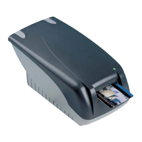
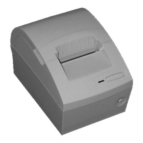
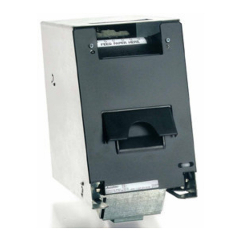
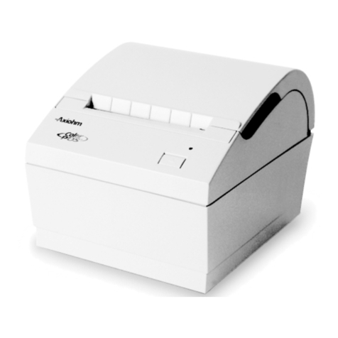
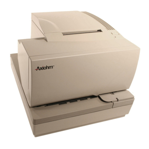
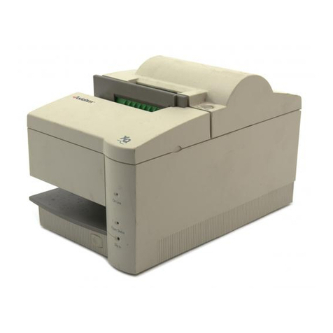
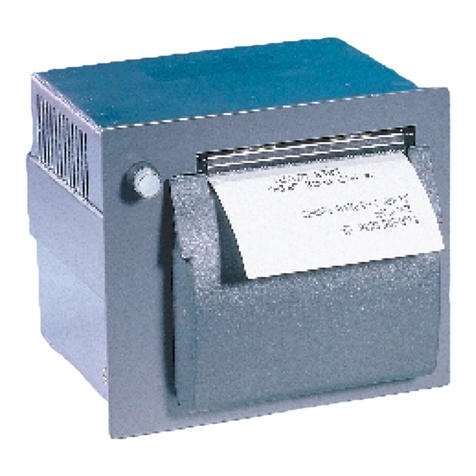
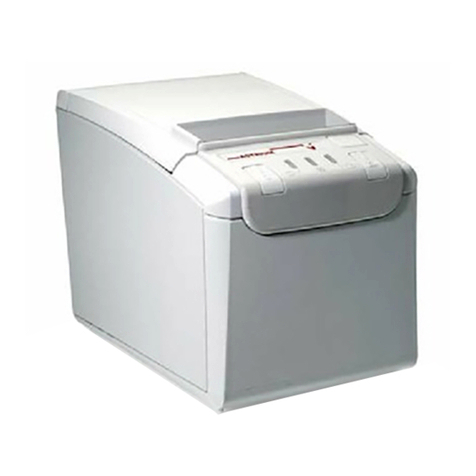
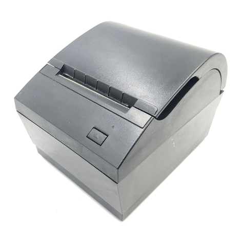
Axiohm A714 User manual

A714 Impact Printer:
Owner’s Guide
A714-D100


A714 Impact Printer:
Owner’s Guide
A714-D100
AXIOHM
Ithaca, New York

April 1998ii
Disclaimer
Information in this document is subject to change without notice. Therefore, before using this
document, consult your Axiohm sales representative for information that is applicable and current.
Axiohm reserves the right to improve products as new technology, components, software, and
firmware become available.
No part of this document may be reproduced or transmitted in any form or by any means,
electronic or mechanical, for any purpose without the express written permission of Axiohm.
Copyright
Copyright © 1998 by AXIOHM
Ithaca, New York USA
All rights reserved
Printed in USA
Confidential, Unpublished
Property of AXIOHM
Trademarks
AXIOHM is the registered trademark of AXIOHM.
Epson is the registered trademark of Seiko Epson Corporation.
ESC/POS is the trademark of Seiko Epson Corporation.
Star is the registered trademark of Star Micronics Co., LTD.
Citizen is the registered trademark of Japan CBM Corporation.
Verifone is the registered trademark of Verifone “The Transaction Automation Company.”
Other trademarks and registered trademarks are the property of their respective holders.

April 1998 iii
Important Information to the User
In order to ensure compliance with the Product Safety, FCC, and CE marking requirements, you
must use the power supply, power cord, and interface cable which were shipped with this product
or which meet the following parameters:
Power Supply
Two CSA Listed, Class 2 power supplies, each with dual-volt output, input rated either 120 Vac, 60
Hz, output rated 25 Vdc at 2A, 9 Vdc at 700 mA; or 240 Vac, 60 Hz, output rated 25 Vdc at 2A, 9
Vdc at 700 mA.
Use of this product with a power supply other than the Axiohm power supply will require you to
test this power supply and Axiohm printer for FCC and CE mark certification.
Interface Cable
A shielded (360 degree) interface cable must be used with this product. The shield must be
connected to the frame or earth ground connection or earth ground reference at EACH end of the
cable.
Use of a cable other than described here will require that you test this cable with the Axiohm
printer and your system for FCC and CE mark certification.
Power Cord
A detachable power cord must be UL listed when used with this product. For applications where
the power supply module may be mounted on the floor, a power cord with Type SJT marking
must be used. For applications outside the US, power cords which meet the particular country’s
certification and application requirements should be used.
Use of a power cord other than described here may result in a violation of safety certifications
which are in force in the country of use.

April 1998iv
Federal Communications Commission (FCC)
Radio Frequency Interference Statement
Warning
Changes or modifications to this unit not expressly approved by the party responsible for
compliance could void the user’s authority to operate the equipment.
Note
This equipment has been tested and found to comply with the limits for a Class B digital device,
pursuant to Part 15 of the FCC Rules. These limits are designed to provide reasonable protection
against harmful interference when the equipment is operated in a commercial or residential
environment. This equipment generates, uses, and can radiate radio frequency energy, and, if not
installed and used in accordance with the instruction manual, may cause harmful interference to
radio communications.
Information to User
This equipment must be installed and used in strict accordance with the manufacturer's
instructions. However, there is no guarantee that interference to radio communications will not
occur in a particular commercial installation. If this equipment does cause interference, which can
be determined by turning the equipment off and on, the user is encouraged to contact Axiohm
immediately.
The Axiohm company is not responsible for any radio or television interference caused by
unauthorized modification of this equipment or the substitution or attachment of connecting cables
and equipment other than those specified by Axiohm. The correction of interferences caused by
such unauthorized modification, substitution, or attachment will be the responsibility of the user.
Industry Canada (IC)
Radio Frequency Interference Statement
This digital apparatus does not exceed the Class B limits for radio noise emissions from digital
apparatus set out in the Radio Interference-causing equipment standard entitled “Digital
Apparatus,” ICES-003 of the Department of Communications.
Cet appareil numérique respecte les limites de bruits radioelectriques applicables aux appareils numériques
de Class B prescrites dans le norme sur le matèriel brouilleur: “Appareils Numériques,” NMB-003 édicté
par le ministère des Communications.”

A714 Owner’s Guide Contents
April 1998 v
ContentsContents
PrefacePreface viivii
Where to Get Additional Information.............................................................................vii
Chapter 1: About the A714 PrinterChapter 1: About the A714 Printer 11
Features and Options.......................................................................................................... 2
Ordering Paper and Supplies............................................................................................. 2
Maintaining and Cleaning the Printer............................................................................... 3
Chapter 2: Operating the PrinterChapter 2: Operating the Printer 55
Using the Controls ....................................................................................................... 5
Changing Paper................................................................................................................... 6
Changing the Ribbon Cassette........................................................................................... 8
Chapter 3: DiagnosticsChapter 3: Diagnostics 99
Level 0 Diagnostics............................................................................................................. 9
Diagnostic Print Tests and Printer Setup Mode..............................................................10
Configuration Report..................................................................................................10
Printer Setup Mode.....................................................................................................12
Extended Self-Test.......................................................................................................15
Chapter 4: When Something Goes WrongChapter 4: When Something Goes Wrong 1717
Problems.............................................................................................................................18
Other Serious Problems.....................................................................................................20
Getting Service ...................................................................................................................20
Chapter 5: CommunicationChapter 5: Communication 2121
Interface ..............................................................................................................................21
Sending Commands...........................................................................................................21
Using DOS to Send Commands.................................................................................21
Using BASIC to Send Commands..............................................................................22
RS-232C Interface Protocols..............................................................................................22
XON/XOFF Protocol ..................................................................................................22
DTR/DSR Protocol .....................................................................................................23
Connectors..........................................................................................................................23
RS-232C Communication Connector Pin Assignments............................................23
Power Cable Connector Pin Assignments.................................................................24
Cash Drawer Connector Pin Assignments................................................................24
Printer Setup Mode............................................................................................................25
Chapter 6: CommandsChapter 6: Commands 2727
ESC-POS Subset .................................................................................................................27
Command Conventions.....................................................................................................27
Command Operation..................................................................................................27
Command Operands...................................................................................................28
List of A714 ESC POS Commands....................................................................................28
Contents A714 Owner’s Guide
April 1998vi
Command Descriptions.....................................................................................................31
Printer Function Commands......................................................................................31
Vertical Positioning Commands................................................................................42
Horizontal Positioning Commands...........................................................................48
Print Characteristics Commands...............................................................................55
Graphics Commands..................................................................................................65
Printer Status Commands ..........................................................................................69
Bar Code Commands.........................................................................................................77
Page Mode Commands...............................................................................................83
Macro Commands.......................................................................................................87
Appendix A: SpecificationsAppendix A: Specifications 8989
Printing Specifications.......................................................................................................89
Speed and Print Modes...............................................................................................89
Paper Specifications....................................................................................................89
Character and Line Specifications .............................................................................90
Print Zone...........................................................................................................................90
Power Requirements..........................................................................................................90
Environmental Requirements...........................................................................................91
Reliability............................................................................................................................91
Appendix B: Character SetsAppendix B: Character Sets 9393
Code Page 254 (Space Page)..............................................................................................93
Code Page 255 (Space Page)..............................................................................................94
Code Page 437 (PC US)......................................................................................................95
Code Page 737 (Greek) ......................................................................................................96
Code Page 860 (PC Portuguese)........................................................................................98
Code Page 863 (PC Canadian-French)..............................................................................99
Code Page 865 (Nordic Languages) ...............................................................................100
Katakana...........................................................................................................................101

A714 Owner’s Guide Preface
April 1998 vii
PrefacePreface
This book is a general guide for operators and supervisors who need to know how to
operate the printer. It is also a technical guide for programmers and system integrators
who need to know the technical information about the printer’s communication; the
programming commands that control the printer; and the character sets and graphics that
are available.
Where to Get Additional InformationWhere to Get Additional Information
The following publications contain more information about the A714 printer. Contact
your sales representative to obtain additional copies of this Owner’s Guide or any of the
publications listed below.
TitleTitle Axiohm NumberAxiohm Number
A714 Impact Printer: Owner’s Guide A714-D100
A714 Impact Printer: Setup Guide A714-D110
A714 Impact Printer: Service Guide A714-D200
A714 Impact Printer: Parts Identification Manual A714-D300

A714 Owner’s Guide Chapter 1: About the A714 Printer
April 1998 1
Chapter 1: About the A714 PrinterChapter 1: About the A714 Printer
Power
Switch
Paper
Feed
Button
Power
LEDPaper
Status
LED
The A714 printer is a fast, reliable, and flexible printer, designed to meet your immediate
and long term needs.
The industry standard RS-232C communication interface allows the A714 to be connected
to any host computer PC or terminal system that uses RS-232C. In addition, the A714
emulates the Epson TM-U200, Epson TM-U300 Star SP-200, Citizen iDP-3540, VERIFONE
900, DP1000, Panasonic, and Axiohm A470 printers with an enhanced instruction set to
take advantage of all the A714 printer features.

Chapter 1: About the A714 Printer A714 Owner’s Guide
April 19982
Features and OptionsFeatures and Options
The A714 printer comes with a variety of standard features. It can also be configured with
the optional components described below.
FeaturesFeatures
• Standard pitch (host selectable): 12.8/16 characters per inch, 32/40 columns
• Drop in paper loading, requires no spindle
• Paper status indicator light (LED)
• Industry standard RS-232C communication interface
• Wall mount option
• ESC/POS simulation with seven selectable printer emulations resident
• Cash drawer connector
OptionsOptions
• Remote power supply
• Paper cutter
Ordering Paper and SuppliesOrdering Paper and Supplies
The following section lists the paper and supplies available for order. In addition to paper
and ribbon casettes, you can order a new printhead, power supply, cables, cash drawer,
and additional documentation.
PaperPaper
PlyPly DiameterDiameter
(Maximum)(Maximum) WidthWidth ThicknessThickness Core InsideCore Inside
DiameterDiameter NumberNumber
One-Ply 3.35 inches
(85 mm) 3 inches
(76.2 mm) 0.028 inches
(0.07 mm) 0.44 inches
(11.1 mm) 103292-044
Two-Ply 3.35 inches
(85 mm) 3 inches
(76.2 mm) 0.008 inches (max)
(0.2 mm) (max) 0.44 inches
(11.1 mm) 103292-043
The paper must not be attached at the core. You may want to use paper with a colored
stripe at the end that signals the paper is running low. Call 1 800 377-2750 to order
paper.

A714 Owner’s Guide Chapter 1: About the A714 Printer
April 1998 3
Other SuppliesOther Supplies
Contact a sales representative to order the supplies listed below. The numbers are for
reference only. Suppliers may use different numbers.
ItemItem TypeType NumberNumber
Ribbon Cassettes Black (2.0 million characters)
Purple (3.2 million characters)
Red/Black (800 thousand characters)
100629-004
100629-005
100629-006
Printhead 100639-029
AC Power Supply North American
European 107074-001
107074-002
DocumentationDocumentation
Contact a sales representative to order the following documentation.
TitleTitle Axiohm NumberAxiohm Number
A714 Impact Printer: Owner’s Guide A714-D100
A714 Impact Printer: Setup Guide A714-D110
A714 Impact Printer: Service Guide A714-D200
A714 Impact Printer: Parts Identification Manual A714-D300
Maintaining and Cleaning the PrinterMaintaining and Cleaning the Printer
There is no customer maintenance required for the A714 printer. However, you may
occasionaly clean the cabinet as needed to remove finger marks and dust. Use any
household cleaner designed for plastics, but test it first on a small, unseen area. The
cabinet finish and materials are durable and resistant to the following:
• Cleaning solutions
• Lubricants
• Fuels
• Cooking oils
• Ultrviolet lights
You can clean lint and paper dust out of the mechanism using low pressure canned air.
Caution: Do not spray or try to clean the printhead or the inside of the printer with any
kind of cleaner. This may damage the printhead or the electronics.

Chapter 1: About the A714 Printer A714 Owner’s Guide
April 19984

A714 Owner’s Guide Chapter 2: Operating the Printer
April 1998 5
Chapter 2: Operating the PrinterChapter 2: Operating the Printer
This chapter describes the printer controls and provides procedures for loading paper
and ribbon cassettes, and replacing the printhead.
Using the ControlsUsing the Controls
Power
Switch
Paper
Feed
Button
Power
LEDPaper
Status
LED
The A714 printer includes the following controls:
• Paper feed button used to advance paper.
• Power switch used to turn the printer on and off.
The A714 also includes a Slow Down mode which prevents damage to the printer by
reducing print speed during long periods of continuous printing. The printed
automatically returns to normal speed when usage returns to normal. Do not cycle or
reset the printer while it is in Slow Down mode or damage may result.

Chapter 2: Operating the Printer A714 Owner’s Guide
April 19986
Changing PaperChanging Paper
The A714 features simple paper loading which is quick and efficient, saving both time
and paper.
Caution: Do not operate the printer if it runs out of paper. The printer will continue to
operate, but data may be lost and the printhead may be damaged.
Removing the Old Paper RollRemoving the Old Paper Roll
Paper
Cover
1
Used
PaperRoll
2
1. Open the rear cover.
2. Remove the used paper roll.

A714 Owner’s Guide Chapter 2: Operating the Printer
April 1998 7
Loading the New Paper RollLoading the New Paper Roll
New
PaperRoll
1
Feed
Rollers
2
3PaperFeed
Button
1. Place the new roll into the printer with the paper coming off the bottom of the roll.
2. Pull out several inches of paper and feed the end into the feed rollers.
3. Close the rear cover and press the Paper Feed button.

Chapter 2: Operating the Printer A714 Owner’s Guide
April 19988
Changing the Ribbon CassetteChanging the Ribbon Cassette
Change the ribbon cassette when the print is too light or the ribbon is frayed.
Printhead
Shield
Ribbon
Ribbon
Cover
Ribbon
CassetteAutto
Cutter
Paper
Cover
1
1
2
3
1. Open both printer covers.
2. If the printer has an auto cutter, lift the cutter bracket up.
3. Pull the used ribbon up and out of the printer and discard it.
4. Snap in the new ribbon cassette.
Make sure the ribbon slides between the printhead and the ribbon shield.
5. If the printer has an auto cutter, lower the cutter bracket back into place.
6. Close the front cover, and then close the rear cover.

A714 Owner’s Guide Chapter 3: Diagnostics
April 1998 9
Chapter 3: DiagnosticsChapter 3: Diagnostics
The following diagnostic tests are available for the A714 printer:
• Level 0 Diagnostics: Performed during the startup cycle .
• Diagnostic Print Tests: Performed using the Paper Feed button.
Level 0 DiagnosticsLevel 0 Diagnostics
The printer automatically perfoms Level 0 diagnostics each time it is turned on. Level 0
diagnostics include the following:
• Motors and solenoids are turned off.
• CRC check of the firmware ROM is performed, external RAM is read.
• Level 0 diagnostics stop if this action fails. Failure is indicated by the printer
stopping operation: printhead does not home, the power LED is red, the printer
is unable to communicate with the host computer.
• Printhead is homed. A fault condition is caused if this action fails.
• The status of all sensors is checked and the status bytes are updated.
If the printer has not been turned on before, or a new EEROM has been installed, the
default values for the printer functions will be loaded into the EEROM during level 0
diagnostics. These values can be changed in Printer Setup Mode. For more information,
see “Printer Setup Mode” on page 12.
When the last step is complete, the Paper Feed button is enabled and the printer is ready
for normal operation. You may also choose to initiate the Diagnostic Print Tests and
Printer Setup Mode.
If the printer does not complete Level 0 diagnostics successfully, the power LED is lit
(red) to indicate the problem. For more information, see “Getting Service” in Chapter 4:
When Something Goes Wrong.

Chapter 3: Diagnostics A714 Owner’s Guide
April 199810
Diagnostic Print Tests and Printer Setup ModeDiagnostic Print Tests and Printer Setup Mode
Two diagnostic print tests are available:
• Configuration Report: Includes read and write tests of internal RAM; checksum test
of internal program memory; and a printed report listing the current emulation, print
speed, flow control, data length, parity, baud rate, and font.
• Extended Self-Test: Checks internal memory, program checksum, print head pin
firing, vertical line alignment, and character fonts and pitches.
You can also use Printer Setup Mode to set the following:
• Printer emulation
• Print Speed
• Flow Control
• Data Length
• Parity
• Baud Rate
• Font
• Auto Line Feed
• Buffer Size
• Font Selections
• International Characters
• Code Page
• Stop Bit
• Busy on Error
Configuration ReportConfiguration Report
The A714 completes a test of internal RAM and a checksum test of internal program
memory, and then produces a printout listing the current configuration settings. A
sample printout is included on the following page. For more information about changing
these settings, see “Printer Setup Mode” on page 12.
To print the configuration report, complete the following steps.
1. If necessary, turn the printer off.
2. Press and hold the Paper Feed button and then press the Power button to turn the
printer on and start the test.
Release the Paper Feed button after printing begins.
The printer tests the internal RAM and the internal program memory and then prints
the configuration report. (See the following page.)
3. If you want to change configuration settings or run the extended self-test, when
prompted, press the Paper Feed button.
Otherwise, wait ten seconds for the printer to return to normal operation.

A714 Owner’s Guide Chapter 3: Diagnostics
April 1998 11
Table of contents
Other Axiohm Printer manuals

Axiohm
Axiohm A721 User manual

Axiohm
Axiohm PCPR Printer User manual

Axiohm
Axiohm TPOSS001 User manual

Axiohm
Axiohm SKGG5xxx Series User manual

Axiohm
Axiohm CMBC-XMBC User manual

Axiohm
Axiohm A795 User manual

Axiohm
Axiohm APM-90 User manual

Axiohm
Axiohm A630 User manual

Axiohm
Axiohm A758 User manual

Axiohm
Axiohm A794 User manual

Axiohm
Axiohm A794 User manual

Axiohm
Axiohm A758 User manual

Axiohm
Axiohm 7193 User manual

Axiohm
Axiohm APOS PRINTER SERIES User manual

Axiohm
Axiohm 24V User manual

Axiohm
Axiohm A794-D100 User manual

Axiohm
Axiohm A794 User manual

Axiohm
Axiohm A220 User manual

Axiohm
Axiohm THTN Series User manual

Axiohm
Axiohm TELESTO User manual