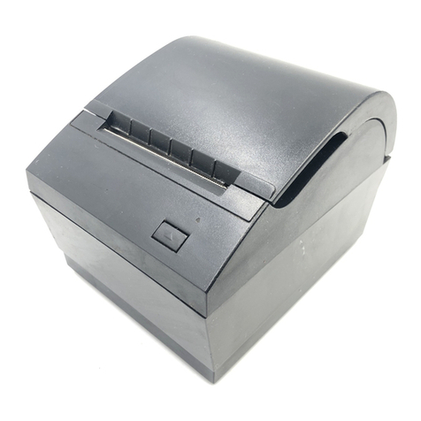
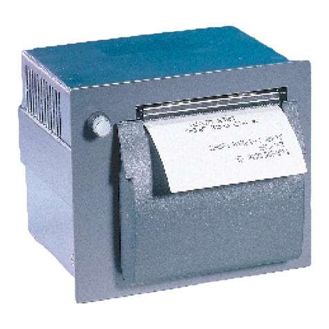
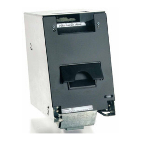
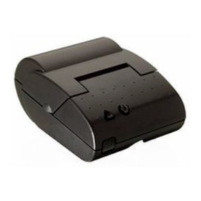
Axiohm CMBC-XMBC User manual

CM/XM Series User Manual Page 3/42 Ref: FDE - 3102473 / A
TABLE OF CONTENTS
1. UNPACKING 5
2. OVERVIEW 5
3. MECHANICAL SPECIFICATIONS 6
3.1. General description 6
3.2. Dimensions of the complete mechanism : 6
3.3. Mechanical views 7
3.4. Optional drive for paper rewinder 9
4. ELECTRICAL SPECIFICATIONS 10
4.1. Nominal Power supply 10
4.2. Nominal Consumption 10
4.3. Description of printhead 10
4.3.1. Function of each 64 bit IC (integrated circuit) 11
4.3.2. Operation of the complete module 12
4.3.3. Electrical specifications of 64-BIT LSI driver 13
4.3.4. Printhead Connection 16
4.4. Unipolar paper feed motor 18
4.4.1. General specification 18
4.4.2. Connection 18
4.4.3. Induction sequence 18
4.5. Bipolar paper feed motor 19
4.5.1. General specification 19
4.5.2. Connections 19
4.5.3. Induction sequence and timing 20
4.5.4. Bipolar stepping motor electric control 21
4.6. Bipolar cutter motor 22
4.6.1. Overview 22
4.6.2. General specification 22
4.6.3. Connection 22
4.6.4. Induction sequence 22
4.6.5. Initialisation Diagram 23
4.6.6. Driving cycle 23
4.7. Unipolar cutter motor 24
4.7.1. Overview 24
4.7.2. General specification 24
4.7.3. Connection 24
4.7.4. Induction sequence 24
4.8. Switch & pitch counter driving 25

CM/XM Series User Manual Page 4/42 Ref: FDE - 3102473 / A
4.9. Cutter micro-switch specifications 26
4.9.1. General specification 26
4.9.2. Connection 26
4.10. Opto-sensor specification 26
4.10.1. Electrical characteristics 26
4.10.2. Connection 27
4.10.3. External circuit 27
5. PRINTER CONTROL TECHNIQUES 28
5.1. Mode 1 28
5.2. Mode 2 29
5.3. Mode 3 30
6. RECOMMENDATIONS 31
6.1. Mechanical recommendations 31
6.2. Housing design recommendations 31
6.3. Energising & de-energising printer 31
6.4. Printing recommendations 31
6.5. Recommendations for paper 32
6.6. General 32
6.7. Cleaning recommendations 32
6.8. Special recommendation for XM** (printer with cutter) 33
7. PAPER SUPPLIERS 34
8. SPARE PARTS 34
9. APPENDICES 35
9.1. APPENDIX 1 : THERMISTOR SPECIFICATIONS 35
9.2. APPENDIX 2 : Paper specification 37
9.3. APPENDIX 3 : Heating time and historical control 38
9.4. APPENDIX 4 : CHANGE PRINTHEAD 41
9.5. APPENDIX 5 : FIT OR CHANGE THE COVER WITH CUTTER 41
9.6. APPENDIX 6 : PRODUCT NAME & CODIFICATION 42

CM/XM Series User Manual Page 5/42 Ref: FDE - 3102473 / A
1. UNPACKING
Each printer mechanism is packaged in an antistatic bag. Observe precautions for handling in
electrostatic protected areas.
2. OVERVIEW
Based on static thermal printing technology, the CM/XM series is a family of user-friendly, highly
reliable devices which have been specially designed to fit in the minimum space.
CMxx : Printer only or printer with optional tear bar cover
XMxx : Printer with cutter
Very small size printer and cutter
Silent mechanism
Option of 4 dots/mm or 8 dots/mm print-heads
Optional cover with tear bar
Optional cover with Guillotine cutter (XMxx)
Easy to connect (only one connector for motor, printhead, opto-sensor and cutter)
Front and bottom paper introduction possible
Optional drive for paper rewinder
SUMMARY OF PRINTER SPECIFICATIONS
ITEM VALUE UNITS
xMBC xMDG -
Printing method Static thermal dot line printing -
Number of resistor dots 192 384 -
Resolution 4 8 Dots/mm
Printing width 48 mm
Paper width 60 mm
Head temperature detection By Thermistor -
Number of steps / dot line 2 1 -
Paper feed / dot line 0.250 0.125 mm
Paper empty detection Opto-sensor -
Operating voltage range Vcc (logic) 4.75-5.25 V DC
Operating voltage range Vch (dot) 20 - 28 20 - 26.4 V DC
Peak printhead current
(all dots ”on ” at nominal value ) 8.25 8.8 A
Current consumption:
V ch (at nominal value) 43 23 mA per resistor dot ”on ”
Current consumption:
V cc (at nominal value) 160 100 µA

CM/XM Series User Manual Page 6/42 Ref: FDE - 3102473 / A
Current consumption:
Stepping motor for paper feed 320 (600 bipolar) mA
Current consumption:
Stepping motor for cutter 500 (1000 bipolar) mA
Storage range - 20 to + 60 °C
Operating range -10 to 50 for CMBC 0 to 50 for CMDG °C
+5 to +45 version with cutter XM**
Electrical life time* 1.2 ×10⁸xMBC 108xMDG pulses
Mechanical life time* 50 50 Km
Relative Humidity (operating) 20 to 85 no condensing *2%
Over all dimensions:
Width (without rewinder)
Depth
Height
CMxx
74.5
61
32
CMxx(cover)
74.5
62.5
36
XMxx
74.8
67
39.2
mm
mm
mm
Weight 140 200 g
Recommended paper 2320061 / WS 752-57 (60µ) Axiohm reference / Arjo Wiggins
Maximum paper thickness 80 µ
Cutter life time (XMxx) 300 000 cuts (with paper 2320061)
* Per AXIOHM standard test conditions (which are mainly : 24V, 25°C, dot printing duty cycle = 30 %)
* 2 for printer with cutter (XM**) the following curve defines Relative Humidity area
HR %
°C
20
80
75
5
35
45
3. MECHANICAL SPECIFICATIONS
3.1. General description
The mechanism consists in :
- Plastic chassis
- Optional hinged cover with tear bar for CMxx or cutter for XMxx
- Cutter with stepping motor and mechanical switch for position detection (XMxx series)
- Stepping motor
- Gear train
- Printhead
- End of paper opto-sensor
3.2. Dimensions of the complete mechanism :
Height :......................................32 (CMxx) / 36 (CMxx with cover) / 39.2 (XMxx) mm
Depth :....................................... 61 (CMxx) / 62.5 (CMxx with cover) / 67 (XMxx) mm
Width (without rewinder option).. 74.5 (Cmxx) / 74.8 (Xmxx) mm
Weight :..................................... 140 (CMxx) / 200 (XMxx) g

CM/XM Series User Manual Page 8/42 Ref: FDE - 3102473 / A
39.2
32
37.9
37
61 65
1.8
74.7
40.75
50.1
23.6
Use self threader screws for plastic, the fixing holes diameter being 2.5 mm, use a maximum diameter of
3 mm for screws and a maximum depth in chassis of 7 mm (from the external edge of holes).
Fig.3 With cutter cover
Fig.4 Chassis fixing
Ground
terminal

CM/XM Series User Manual Page 9/42 Ref: FDE - 3102473 / A
This distance is 8 mm for XMxx
Opto- sensor position
The position of the end of paper opto-sensor relatively to the paper allows top off form detection
Paper sensitive layer
paper path
direction
paper inlet 1
paper inlet 2
5.5
5
77
Fig. 6 Opto- sensor position
3.4. Optional drive for paper rewinder
An optional pulley can be fitted on the printer side to drive a paper re-winder (see drawings on preceding
pages)
Paper path and distance from line of dots to line of cut
7 mm
Paper inlet 1
Paper inlet 2
Fig.5 paper path
Paper outlet

CM/XM Series User Manual Page 10/42 Ref: FDE - 3102473 / A
4. ELECTRICAL SPECIFICATIONS
4.1. Nominal Power supply
Printer CMBC / DG
XMBC / DG Units
Printhead :
Logic (Vcc)
Dot line 5
24 V DC
V DC
Stepping motor 24 V DC
4.2. Nominal Consumption
Printer CMBC
XMBC CMDG
XMDG Units
Printhead :
Heating
current / dot
(Vch) at nominal values 43 23 mA
Logic current / dot (Vcc) 160 100 µA
Stepping Motor (2 activated
phases) for paper feed 320 unipolar
600 bipolar mA
Stepping Motor (2 activated
phases) for cutter XMxx 500 unipolar
1000 bipolar mA
Maximum instantaneous
current per dot line (at 24V) 8.25 8.8 A
4.3. Description of printhead
Printer CM/XMBC CM/XMDG UNIT
Driver chips
(64 bit BiCMos LSI) 3 6 -
Nominal dot resistance 530 (±15 %) 1000 (±3 %) ohms
Nominal dot energie
(in standard conditions) 2.0 0.8 mJ
Max printing speed (with 24V
power supply)
(with dot historical control)
8 8 cm/sec

CM/XM Series User Manual Page 11/42 Ref: FDE - 3102473 / A
4.3.1. Function of each 64 bit IC (integrated circuit)
64 bits buffer
registers
64 bits shift
registers
SERIAL
OUTPUT (SO)
Strobe
Serial
Input (SI)
CLOCK
OE1
OE2
Output
Enable (OE)
Vch
Line of resistor dots -
1 2 3 4 ...... (OUTPUTS).... 62 63 64
Fig.7 Driver IC schematic
These circuits are supplied by 5V +/- 5% logic voltage
Each circuit features 64 open collector transistors
64-bit shift register
64-bit memory register
Each circuit controls 64 resistor dots on the printhead
The heating element power supply VCH is not connected to the Driver ICs but only to the resistive line
of dots itself. The driver ICs are connected via a pattern of high current gold interconnecting traces to the
line of resistor dots.
The dot line is of the interdigitated type, in order to maintain the tight definition of the dot geometry
and resistance. In such a scheme the heating element power supply VCH forms a ‘comb’ of traces over
which the resistive line of dots is laid. The outputs of the driver ICs form a second comb interdigitated with
the first.

CM/XM Series User Manual Page 12/42 Ref: FDE - 3102473 / A
4.3.2. Operation of the complete module
OE 2
SI SO
CHIP
1
OE 1
IN
R64R1Resistors
OE (2N-1)
CLK
STROBE
SO
CHIP
N
OE 2N
OUT
SI
Resistors R 64
R 1
Fig.8
- Data to be printed is clocked into a shift register formed by cascading "n" chips.
- E.g. 384 dot head uses 6 chips with the SO output of chip 1 used as the SI input for chip
2 etc. Respectively, the SO output of chip 2 is used as the SI input for chip 3 etc.
After 384 clocks, the initial piece of data entered corresponds to the last (384th) dot of the
line (the R64 output of the 6th chip). The last bit of data entered will correspond to the first
dot of the line(R1 of the first chip).
Printhead
bottomview
paper side
Line of
dots
Printhead
substrate
Thermal paper
Sensitive layer
chip
1 chip
n
paper feed
direction
R1 of chip 1 R1 of chip 1
Fig.9 Routing of data to the resistor dots

CM/XM Series User Manual Page 13/42 Ref: FDE - 3102473 / A
4.3.3. Electrical specifications of 64-BIT LSI driver
4.3.3.1. General
xMBC xMDG
PARAMETER MIN MAX MIN MAX UNIT
Max.voltage at outputs 1 to 64 -0.5 28 26.4 V
Max.input voltage -0.5 7Vch V
Max.output current/dot* - 60 -27.3 mA
Total max.output current * - 2.9 -1.7 A
*64 ×60 mA ×0.75 % = 2.9 A ( for xMBC )
4.3.3.2. Other
The specifications given below are given for the following conditions :
- Room temperature
- Logic voltage on chip : 4.75 V < Vdd < 5.25 V,
- Clock frequency : 10 MHz (xMBC) / 4MHz (xMDG).
xMBC xMDG
Logic Current (5 V) Conditions Values Conditions Values Symb
Current per controlled element (dot) Vdd = 5V 160 µA - - Idd
Min.high-level input voltage 2.8V Vcc = 5V 0.7Vcc Vih
Max.low-level input voltage 0.8 V Vcc ≤≤ 5V 0.3 Vcc Vil
Max.high-level input current +/-10µA 0.5µA Iih
Max.low-level input current +/-10 µA 0.5µA Iil
Min.high-level output voltage Io = Iohmax 2.8 V Vcc = 4.5 4.45 V Voh
Max.low-level output voltage Io = Iolmax 0.4 V Vcc = 4.5 0.05 V Vol
Max.high-level output current 0.1 mA - - Iohmax
Max.low-level output current -0.5 mA - - Iolmax
Heating current (xMBC) Conditions Values Symb
Max.power output current Vdon=Vdonmax -60 mA Idomax
Max.output leakage
current Vdon=24 V 1 µA Idoleak
Max.output voltage Idout=Idomax 1300 mV Vdonmax
Deviation for Vdonmax 200 mV dVdon

CM/XM Series User Manual Page 14/42 Ref: FDE - 3102473 / A
4.3.3.3. Timing
DIN
CLK
SO63
STB
OEx
DOUTx
Tsdc Thdc
Tr
Tf
Tclk
Tdcs0
Tscl Tst Tdos Tdoec Tdcoe Tdoec
Trdo
Tdoedo Tddooe
Tfdo
Fig.10 Timing Diagram for xMBC
t8 t9 t8 t10
t6 t5
t7
t4t3
Tclk
Clock
Serial in
Serial out
Strobe
OEn:
Data Out n :
t2
t7
90%10% 90%
10%
Fig.11 Timing diagram for xMDG

CM/XM Series User Manual Page 15/42 Ref: FDE - 3102473 / A
xMBC xMDG
Sym Description Min Max Min Max Un
it
Tclk Serial clock period 100 250 ns
Tr, Tf Rise, fall time f clock, 10% -> 90% 10 - - µs
Tdoec Clock to OE delay time 10 - - µs
Tdcoe OE to clock delay time 100 - - ns
Tsdc / t3 Data in to clock setup time 20 50 ns
Thdc / t4 Data in from clock hold time 20 10 ns
Tdcs0 / t7 Serial data out from clock delay * 80 120 ns
Tdcs1 Serial data out from clock delay ** 110 - - ns
Tscl / t6 Clock to strobe delay time 100 100 ns
Tst / t5 Strobe high time 100 100 ns
Tdos Strobe to OE delay time 100 - - ns
Tdoedo / t8 OE to data out delay time *** 0.25 2µs
Tfdo / t9 Data out fall time, 10% -> 90% *** 10.5 µs
Tddooe OE to data out delay time *** 1-µs
Trdo / t10 Data out rise time, 10% -> 90% *** 1 2 µs
*, **, *** are to be considered only for xMBC
*10 pf load on output, all inputs Vil = Vss + 0.5V Vih = VDD - 0.5V.
** 10 pf load on output, standard Vil and Vih.
*** Vdd = 5V, Temp = 25°C, with a resistant load, R1 = 500 ΩΩ, connected to 24V.Can not be
measured. These parameters will be assured by design after characterisation of the prototypes.
TIMING RESTRICTIONS (xMBC)
- No clock transistions may take place during Tscl, tst, Tdoes, Tdoec,and Tdcoe,
- Data input must change on the falling edge of the clk-input,
- Data must be stable during Tsdc, Tr and Thdc.

CM/XM Series User Manual Page 16/42 Ref: FDE - 3102473 / A
4.3.4. Printhead Connection
PINOUT OF ZIF 30 CONNECTOR
XM/CMxx PRINTER
PIN N° SIGNAL PIN N° SIGNAL
1Vch 16 GND
2Vch 17 GND
3Cutter motor B2 18 GND
4Cutter motor B1 19 GND
5Cutter motor A1 20 GND
6Cutter motor A2 21 Thermistor 1
7Switch Out 22 Thermistor 2
8Anode Opto-sensor 23 OE1
9Collector Opto-sensor 24 Data In
10 Data Out 25 Paper feed motor B2
11 Clock 26 Paper feed motor B1
12 Strobe 27 Paper feed motor A2
13 OE3 28 Paper feed motor A1
14 Vcc 29 Vch
15 OE2 30 Vch
1 30
connector ZIF 30
This connector (fitted on your printer) should be connected to your board with a 30 pins flex to another compatible
connector.
Compatible connectors suppliers and references : Molex 5597 3951 3304 straight connector
: Molex 5597 3951 3303 bent connector
: Stocko MZF 9390 60 3030 straight connector
: Stocko MZF 8900 60 3030 bent connector

CM/XM Series User Manual Page 18/42 Ref: FDE - 3102473 / A
4.4. Unipolar paper feed motor
4.4.1. General specification
- Operating range : 20V < V < 28V (24V nominal)
- Coil resistance : 150 Ω±10%
- Number of phases : 4
- Drive method : 2 phases on
- Current drawn 160 mA per phase
- Maximum starting frequency 500 pps
- Steps to initialize paper feed 4
- Step angle : 7° 30 ‘
- Number of steps per revolution : 48
Acceleration table : this motor takes 20 steps to reach its maximum speed ( 1600 µs which means
600 pps and 75 mm/s). In this table the first row shows the motor pitch and the second one shows
the motor phase time in µs.
12345678910
2000 1997 1990 1981 1967 1950 1930 1908 1883 1858
11 12 13 14 15 16 17 18 19 20
1832 1806 1781 1757 1734 1715 1698 1683 1674 1667
4.4.2. Connection
Connection to the PCB
PIN n°
Wire color
Motor
1
2
3
4
5
6
red
brown
black
orange
yellow
A1
B1
B2
COM
A2
empty
A1
A2
B1
Com
B2
The PCB is then connected to the flexible containing all supply and control, see page 16.
4.4.3. Induction sequence
BLACK BROWN ORANGE YELLOW RED
RED
Step 1 - -
Step 2 - - +
Step 3 - -
Step 4 - -
Voltage on cable is negative where shown as “–
Otherwise cable is floating except if shown as

CM/XM Series User Manual Page 19/42 Ref: FDE - 3102473 / A
External circuit
Examples :
1when clamping diode is not integrated to the stepper motor driver
2when clamping diode is integrated to the stepper motor driver
Stepper
Motor
Driver
Stepper
Motor
Driver
Vch (24V) Vch (24V) Vch (24V) Vch (24V)
Motor winding Motor winding
Zener diode
24V Zener diode
24V
Clamping diode
1
2
Note : If the phase currents are switched to zero, the position in the sequence must be memorised.
When the winding currents are re-applied the polarities corresponding to the last known position
should be used. This ensures that the motor will re-start correctly. (this is still true for next chapter
(bipolar motor))
4.5. Bipolar paper feed motor
An optional bipolar motor is available for paper feed
4.5.1. General specification
- Recommended control voltage : 24V
- Coil resistance : 20 Ω±10%
- Number of phases : 4
- Step angle : 7° 30'
- Paper feed for one printing line : 2 (CMBC) / 1 (CMDG)
- Recommended control current : 300 mA (peak)
- Maximum starting frequency : 500 pps
4.5.2. Connections
6
A1 A2
B1 B2
PIN n° Wire color Motor
1
2
3
4orange
black
B2
A2
A1
B1
brown
yellow
5
empty
empty
Wire length
60 ±10 mm
Connection to flexible

CM/XM Series User Manual Page 20/42 Ref: FDE - 3102473 / A
4.5.3. Induction sequence and timing
ORANGE
STEP 1
STEP 2
STEP 3
STEP 4
BLACK BROWN
YELLOW
Voltage on cable is negative where shown as “-“.
Voltage on cable is positive where shown as “+”.
Motor Steps
t1
t2
current into
winding A
current into
winding B
Currents removed
Currents
restored
0
+
-
-
+
0
- There are 4 different conditions for the motor windings:
The sequence is :
AB AB ABAB
AB
stands for “A is positive
and B is negative” etc.
AB
Where
•This electrical sequence corresponds to a sequence of 4 consecutive mechanical positions. The
sequence is repeated 12 times for each revolution.
- t1 = 0.4 ms
- t2 = 2 ms
Motor initialisation
Once the initial winding currents have been applied they must be maintained for a time t1. Once
this time has passed the motor may be operated by changing the winding currents in the usual way.
The same acceleration table can be used for bipolar motor than for unipolar motor (see page 18)
To take-up the play in the gears it is necessary to operate the motor for 16 steps before starting to
print.
This manual suits for next models
1
Table of contents
Other Axiohm Printer manuals

Axiohm
Axiohm TELESTO User manual

Axiohm
Axiohm A794 User manual

Axiohm
Axiohm A220 User manual

Axiohm
Axiohm APOS PRINTER SERIES User manual

Axiohm
Axiohm A795 User manual

Axiohm
Axiohm A758 User manual

Axiohm
Axiohm THTN Series User manual

Axiohm
Axiohm APM-90 User manual

Axiohm
Axiohm A795 User manual

Axiohm
Axiohm A794 User manual

Axiohm
Axiohm A758 User manual

Axiohm
Axiohm A714 User manual

Axiohm
Axiohm TPOS PRINTER SERIES User manual

Axiohm
Axiohm A721 User manual

Axiohm
Axiohm A630 User manual

Axiohm
Axiohm Astrium User manual

Axiohm
Axiohm 7193 User manual

Axiohm
Axiohm SKGG5xxx Series User manual

Axiohm
Axiohm A794-D100 User manual

Axiohm
Axiohm TPOSS001 User manual