Axiohm THTN Series User manual

AXIOHM, 1-9 Rue d’Arcueil
BP 675, 92542 Montrouge Cedex, France
Tel : (33) (0) 1 47 46 78 00 Fax (33) (0) 1 46 55 13 44
1 / 25
THERMAL PRINTER MECHANISM
USER'S MANUAL
THTN Series
Reference : FDE – 3106531 issue-Z
January - 01

THTN series User's Manual page 2 / 25 Ref : FDE – 3106531 - Z
IMPORTANT
This manual contains the basic instructions to run your printer. Read it
carefully before using your printer paying full attention to the section :
Recommendations .

THTN series User's Manual page 3 / 25 Ref : FDE – 3106531 - Z
CONTENTS
1. UNPACKING............................................................................................................................................................4
2. OVERVIEW..............................................................................................................................................................4
3. MECHANICAL SPECIFICATIONS......................................................................................................................6
3.1 EXTERNAL DIMENSIONS.......................................................................................................................................6
3.2 FIXING ELEMENTS................................................................................................................................................6
3.3 CHASSIS MOUNTING .............................................................................................................................................6
3.4 COVER SWITCH POSITION .....................................................................................................................................6
3.5 COVER AXIS POSITION ..........................................................................................................................................7
3.6 USEFUL DISTANCES..............................................................................................................................................7
4. ELECTRICAL SPECIFICATIONS........................................................................................................................8
4.1 NOMINAL POWER SUPPLY ....................................................................................................................................8
4.2 NOMINAL CONSUMPTION OF PRINTER...................................................................................................................8
4.3 DESCRIPTION OF PRINT-HEAD...............................................................................................................................8
4.3.1 Function of 64-BIT LSI drivers chart and operation..................................................................................9
4.3.2 Electrical specifications of 64-bits LSI driver...........................................................................................11
4.3.3 Print-head connection...............................................................................................................................13
4.4 BIPOLAR STEPPING MOTOR.................................................................................................................................14
4.4.1 Characteristics..........................................................................................................................................14
4.4.2 Motor connection......................................................................................................................................14
4.4.3 Induction sequence and timing (paper feed).............................................................................................15
4.4.4 Printing mode : .........................................................................................................................................15
4.5 SENSORS SPECIFICATIONS...................................................................................................................................16
4.5.1 Cover detection micro-switch....................................................................................................................16
4.5.2 End of paper opto-sensor..........................................................................................................................16
4.5.3 Recommended use for Opto-sensor...........................................................................................................17
5. PRINTER CONTROL TECHNIQUES ................................................................................................................18
5.1 MODE 1..............................................................................................................................................................18
5.2 MODE 2..............................................................................................................................................................19
5.3 MODE 3..............................................................................................................................................................20
6. RECOMMENDATIONS........................................................................................................................................21
6.1 MECHANICAL RECOMMENDATIONS ...................................................................................................................21
6.2 ELECTRICAL RECOMMENDATIONS .....................................................................................................................21
6.3 MOTOR DRIVING RECOMMENDATIONS ..............................................................................................................21
7. HEATING TIME....................................................................................................................................................22
7.1 HISTORICAL CONTROL .......................................................................................................................................22
7.2 HEATING TABLE.................................................................................................................................................23
7.3 THERMISTOR SPECIFICATIONS............................................................................................................................24
8. INDEX......................................................................................................................................................................25
THTN series User's Manual page 4 / 25 Ref : FDE – 3106531 - Z
1. UNPACKING
Each printer mechanism is packaged in an antistatic bag. Observe precautions for handling in electrostatic
protected areas.
2. OVERVIEW
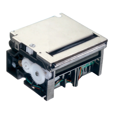
Based on static thermal printing technology, the THTN series is a family of user-friendly, highly reliable
devices which have been specially designed with 5Vdots line and very small size, to suit independent terminal
applications.
The printer can be used either with or without clamshell cover, an optional tear bar is available, and the
mechanism can tolerate a latch if required.
SUMMARY OF PRINTER SPECIFICATIONS
ITEM VALUE UNIT
Printing method Static thermal dot line printing -
Number of resistor dots 384 -
Resolution 8 Dots/mm
Printing width 48 mm
Paper width 58 or 60 mm
Head T° detection Thermistor -
Paper feed pitch 2 Motor steps
0.125 mm
Paper empty detection Opto-sensor -
Operating voltage range Vcc (logic) 2.7 to 5.5 V DC
Operating voltage range Vch (dot) 3 to 8.5 V DC
Current consumption:
Vch (at nominal value : 5V)
29 mA per resistor dot « on »
Current consumption:
Icc (at nominal value : 5V)
I leak
42
0.2
mA
mA
Current consumption:
Stepping motor (at nominal value)
277 mA per activated phase
Maximum number of dots energised
simultaneously 128* -
* The maximum current allowed in printhead is 5A, but the printing density variation may become significant
when the number of dots energised simultaneously becomes greater than 64 (128 dots "on" correspond to 5A
when applying 5V).

THTN series User's Manual page 5 / 25 Ref : FDE – 3106531 - Z
ITEM VALUE UNIT
Storage - 20 to + 60 °C
Relative humidity 20 to 80 %
Operating range 0 to +50 °C
Electrical lifetime* 0.5 108Pulses
Mechanical lifetime* 50 KM
Dimensions:
Width
Depth
Height
72
39
16
mm
mm
mm
Weight 40 g
Recommended paper JUJO TF50KSE3 -
Maximum paper thickness -80 g/m2with front paper path
-130 g/m2with underneath paper path
For underneath paper path this value can be overshot with restrictions : if
needed contact technical support.
Maximum printing speed see "heating time" : depends on voltage, temperature and control way
Specified standards IEC 68-2-6, IEC 68-2-29, IEC 68-2-36
* Per AXIOHM standard test conditions (which are mainly 5V, ≈
≈≈
≈25°C, dot printing duty cycle = 30%)

THTN series User's Manual page 6 / 25 Ref : FDE – 3106531 - Z
3. MECHANICAL SPECIFICATIONS
Note : general tolerances
±
0.2 (when no other is specified)
3.1 External Dimensions
3.2 Fixing Elements
3.3 Chassis mounting
Fixing holes position is shown on figure 3.2, use 3 x M2.5 self threading screws pan head eco-syn length 6 mm
(for example from our supplier BOSSARD) for the 3 diameters Ø2,2 ±0.05.
3.4 Cover switch position
The cover must contain a spur to activate the switch, its lateral position is given on the following view
relatively to the platen axis. Force and shape of the spur on cover should give the indicated position to make sure the
switch is in open position (thus door closed).
7
2
f
rom platen axis to upper face of
switch lever

THTN series User's Manual page 7 / 25 Ref : FDE – 3106531 - Z
3.5 Cover axis position
nThe inlet angle for the platen axis is from 3.5° to 11°
nThe optimum position for setting cover axis close to the mechanism is on the platen axis plan (up to 30mm).
nThe cover axis should not be fitted above the platen axis plan
Those possible positions depend on the play of platen axis in its fixations to the cover
Example 1: the cover axis is on the same plan than the platen axis at 30 mm.
Example 2: the cover axis is 65 mm from the platen axis and 8.5 mm below the platen axis plan.
3.6 Useful distances
nDistance between opto-sensor and line of dots : 11 ±1.5 mm
nDistance between opto-sensor and cut line (with tear bar) : 14 ±1.5 mm
nTow positions for opto sensor : Middle lateral position 30.15 mm from paper path guide
Set on right side at 19.5 mm from the paper path guide
1
9.
4
30.2
The cover can be set between 56 and 60 mm (2mm on each side) it
is recommended to use a maximum of 1.8 mm only on each side
55.8 0
-0.1
1.8 mm
1.8 mm
usable width for fixing
Shaft diameter : 3- 0.02
0
platen axis plan
30 m
m
Possible cover axis
p
ositio
n
Exam
p
le 1
Example 2
Platen inlet/outlet angle
Important note : when the mechanism is used with both
Clamshell and tear bar option, the platen axis must be free to
move 1.5 mm in its holders as shown on the drawing below .
This allows the platen path without pushing against the tear bar.
cover side
(platen holder) Tear bar side
1.5 mm
platen axis

THTN series User's Manual page 8 / 25 Ref : FDE – 3106531 - Z
4. ELECTRICAL SPECIFICATIONS
4.1 Nominal Power supply
Table 1 Nominal power supply
Printer THTN
Printhead :
Logic (Vcc)
Dot line 3.3 / 5
5V DC
Stepping Motor 5
4.2 Nominal consumption of printer
Table 2 Nominal consumption of printer
Printer THTN Units
Printhead : Heating current / dot (Vch) 29 mA
Logic current (Vcc) 42 mA
Stepping motor current (2 activated
phases) 544 mA
4.3 Description of print-head
Printer THTN
Driver chips 6-
Operating range (Vcc) 2.7 to 5.5 *1V DC
Mean dot resistance (±
±±
±4%) 173 Ω
Nominal dot supply voltage 5 (min=3, max=8.5) V DC
Nominal Heating current per dot 29 mA
Max. number of dots to heat at once 128 *2-
*1 Filter any transient signal and parasitic on this line. Separate Vcc from Vch because Vch can go lower
than 4.75 Volts. Vcc must be connected to the same power supply than the other electronic circuits
which drive the printer.
*2 The aim is to avoid current greater than 5A (128 dots "on" give 5 A when applying 5V).

THTN series User's Manual page 9 / 25 Ref : FDE – 3106531 - Z
4.3.1 Function of 64-BIT LSI drivers chart and operation
The LSI power and multiplexing circuit drivers located on the thermal printhead provide power
control from logic signals and the DC power supply voltage.
These circuits are supplied by 2.7 to 5.5 V ± 5% logic voltage. Take care to filter transient and
parasitic on all logic lines. Undetermined states can happen and destroy the head. The power source
should be disconnected from the logic source. The logic source must be connected to the same source as
the electronic circuits in charge of controlling the printer.
Each circuit features 64 open collector transistors, a 64-bit shift register and a 64-bit memory register.
Each circuit controls 64 resistor dots on the printhead.
SERIAL
OUTPUT (SO)
64 bits buffer
register
64 bits shift
register
Strobe
Serial
Input (SI)
CLOCK
Output
Enable (OE)
Vch
Line of resistor dots -
GND
1 2 3 4 ...... (OUTPUTS).... 62 63 64
Figure 1 driver chart

THTN series User's Manual page 10 / 25 Ref : FDE – 3106531 - Z
note : see page 11 and 12 for the available signals on the printer connection.
OUT
CLK
Strobe
IN
SI SO SI SO
Resistors Resistors
R64 R1 R64 R1
OE n OE n+1
CHIP n CHIP n+1
Figure 2 Routing of data to the thermistor dots
paper path
direction
Figure 3 Dots print order
The first bit of data entered will be the first bit of data printed (FIFO).

THTN series User's Manual page 11 / 25 Ref : FDE – 3106531 - Z
4.3.2 Electrical specifications of 64-bits LSI driver
4.3.2.1 General electrical description of drivers
Table 3 Description of drivers
Description Min Maxi Unit
Max. voltage at outputs 1 to 64 8.5 Volt
Max. voltage any other pin Vcc Volt
Max. output current 51 mA
Total max. output current (64
dots "on") 3.26 A
4.3.2.2 Other
The specifications given below are given for the following conditions :
Logic voltage on chip : 2.7 V < Vcc < 5.5V (care should be taken to filter any transient
signal or parasitic in order to keep the driver in a known state: failure to observe this may result in
head destruction)
Clock frequency (max.) : 8 MHz (4.5 to 5.5V)
3 MHz (2.7 to 4.5V)
Table 4 Logic current (3 / 5 V)
CONDITIONS VALUES SYMBOL
Vcc supply current 64 drivers on +
Time on / Time off < 75% 4 mA Idd
Min. high-level input voltage Vcc ≤5 Volts 0.7 ×Vcc Vih
Max. high-level input voltage Vcc ≥5 Volts Vcc Vih
Min. low-level input voltage 0 Vil
Max. low-level input voltage 0.3 ×Vcc Vil
Max. high-level input current 0.5 µA Iih
Max. low-level input current 0.5 µA Iil
Min. high-level output voltage open Vcc = 5V 4.45 V Voh
Max. low-level output voltage 0.05 V Vol

THTN series User's Manual page 12 / 25 Ref : FDE – 3106531 - Z
4.3.2.3 Timing
t6t5
t4
t3
Tclk
Clock
Serial in
Serial out
OE
Strobe
Data Out :
t2
t7
t9 t9
Figure 4 LSI driver timing chart
Serial in : Serial input for data to be printed
Clock : Serial/parallel shift register clock, activated on leading edge of pulse (rest
level = logic 0) Maximum clock frequency is 8 MHz.
Serial out : Serial data out sent back to the connector of the thermal head
STROBE : Signal for putting data into memory, active on logic level 0 (rest level =
logic 1)
OE : Output Enable (OE1 to OE6) power activation signals active at logic
level 1.
Data Out n : Internal data out to heating points (not available on connector)
Note : All these inputs are CMOS compatible.
5 LSI driver symbols
5V / 8 MHz 2.7V / 3MH
z
Symbol Description Min Maxi Min Maxi Unit
Tclk Clock pulse width 70 110 ns
t2 Clock - SI set-up time 40 100 ns
t3 Clock – SI hold time 10 10 ns
t4 Serial out delay time 85 230 ns
t5 Clock – strobe set up time 100 250 ns
t6 Clock – strobe hold time 50 50 ns
t7 Strobe pulse width 100 200 ns
t9 OE data out delay time 15 15 µs
Vcc = 5V or 2.7V, Temp = 25 °C with resistive load.

THTN series User's Manual page 13 / 25 Ref : FDE – 3106531 - Z
4.3.3 Print-head connection
Table 6 Pinout of the printer flex cable
Pin Number Signal Comment
1 Switch 1
2 Switch 2
3Vch
4Vch
5 Data-in Data input
6 OE6 OE for driver 6
7 OE5 OE for driver 5
8 OE4 OE for driver 4
9 GND GND
10 GND GND
11 GND GND
12 GND GND
13 Thermistor2 Thermistor2
14 Thermistor1 Thermistor1
15 OE3 OE for driver 3
16 OE2 OE for driver 2
17 OE1 OE for driver 1
18 Vdd
19 CLOCK Clock signal for serialising data to line
20 STROBE Strobe signal for line print
21 Data-out Data out
22 Vch
23 Vch
24 B0 Paper feed motor B0
25 A0 Paper feed motor A0
26 A1 Paper feed motor A1
27 B1 Paper feed motor B1
28 Anode opto Anode of end of paper opto-sensor
29 Opto ground
30 Collector opto Collector of end of paper opto-sensor
Contact side
1
30
Contact side
about 45 mm 6.5 mm
For the connection of the mechanism Axiohm recommend the following 30 pins connectors (from printhead
flex to board) :
-Molex series 5597 reference 39.51.3304 (straight connector).
-Molex series 5597 reference 39.51.3303 (90° bent connector).

THTN series User's Manual page 14 / 25 Ref : FDE – 3106531 - Z
4.4 Bipolar stepping motor
This motor is used to drive the platen for paper feed, it is a bipolar stepping motor, its characteristics
are described bellow.
4.4.1 Characteristics
Table 7 Stepping motor specifications
Recommended control voltage 5 VDC
Coil Resistance 18 Ω
Number of phases 2 (bipolar)
Pitch angle 18°
Number of steps per revolution 20
Paper feed for 2 motor steps 0.125 mm
Recommended control current 277 (=5V/18Ω)mA/phase
Maximum starting speed * 720 (=45mm/s) step/s
* to go faster : an acceleration ramp up must be achieved.
For the motor driving, see the following page and the chapter "Recommendations"
4.4.2 Motor connection
The PCB is then connected to the main flex cable containing all supply and control.
See page 13 : pin 24 to 27 of the flex cable.

THTN series User's Manual page 15 / 25 Ref : FDE – 3106531 - Z
4.4.3 Induction sequence and timing (paper feed)
Table 8 Motor feed timing diagram
IP1
IP2
Motor Steps
t1
t2
Heating cycles
Note that each time the motor has been stopped for more than 8 ms, the next step should be
longer by 1 ms in order to restart the motor in the appropriate position.
Motor initialisation :
This operation is necessary to place the motor in a good position when the printer electronic is
powered on or reset. Both phases must be powered with the same current during t1=1 ms. It must be
followed by 16 motor steps in order to compensate the play in the gears.
4.4.4 Printing mode :
There are 4 different positions for the motor phases.
The circulation is :
P1= A0B0 ; P2= A1B1
__ __ __ __
P1P2 ÞP1P2 ÞP1P2 Þ P1P2 Þ P1P2
The position of the phases must be kept in memory while the phase currents are switched to
zero in order to restart the motor in a good position.
IP= ± 277 mA
t2 > 1.3 ms
During printing, the motor phases should be maintained otherwise a paper motion can occur and
induce unevenly spaced sublines. A good way to achieve this without over heating the motor is to keep
the motor phases "on" when the buffer contains data, and to release them when the buffer is empty.

THTN series User's Manual page 16 / 25 Ref : FDE – 3106531 - Z
4.5 Sensors specifications
4.5.1 Cover detection micro-switch
4.5.1.1 General
Contact resistance : < 1 Ω initial (< 2 Ωafter life time)
Maximum rating : 0.1 A 30 V DC
4.5.1.2 Connection
The switch connection is integrated with the printhead flexible (See page11 and 12)
Switch Door
closed open
open closed
4.5.2 End of paper opto-sensor
This opto-sensor detects the end of paper
4.5.2.1 Electrical characteristics
Absolute maximum ratings
IF (mA) VR (V) PD(mW) VCEO(V) IC(mA) PC(mW)
50 5 75302050
Operating characteristics
VF (V) IR (µA) ICEO (A) IO (mA) VCE(sat)(v) tr (µs)
Value Maxi 1.3 Maxi 10 Maxi 2.10-7 mini 90 µA - Typical 30
IF = 10 mA IC = 0.1 mA
Conditions IF = 10 mA VR = 5 V VCEO = 10V VCE = 5 V -RL = 1 kΩ
4.5.2.2 Connection
Integrated with the printhead connection (See page13, pins 28 to 30)

THTN series User's Manual page 17 / 25 Ref : FDE – 3106531 - Z
4.5.3 Recommended use for Opto-sensor
The user should be aware that the opto-sensor characteristics have very wide tolerances. We thus
recommend the use of one of the schematics below.
4.5.3.1 Opto Sensor : Sample minimal external circuit
47KΩ
Vo
PRINTER
OPTO-SENSOR
VCC(5V)
if
Condition:
For If = 20 mA ......... Output signal is LOW when paper is PRESENT Vo<0.7V.
......... Output signal is HIGH when paper is EXHAUSTED Vo>3.4V.
4.5.3.2 Sample external circuit with low consumption
47KΩ
Vo
10KΩµp output port
OPTO--SENSOR 178Ω
BC807
PRINTER
VCC(5V) VCC(5V)
if
Condition:
Pulse wave from output port with low level during 0.6 ms, measuring Vo 0.2 ms after
pulse falling edge.
Same conditions for output signal Vo as chapter above.

THTN series User's Manual page 18 / 25 Ref : FDE – 3106531 - Z
5. PRINTER CONTROL TECHNIQUES
Printer control techniques in order to operate the printer. We depict hereafter three possible modes.
5.1 Mode 1
- The paper feeds itself automatically during the heating cycle thereby permitting a high speed to be
achieved. (in this mode, it is recommended to use historical control, see chapter : "Heating Time")
End of
printing
Transmission of data
in series (Din)
in step with CLK
Printing of n
dot line
Motor
feed
Transfer to
memory
stage (STROBE)
Heating controlled
through
OE 1,OE 2,...OEn
simultaneously
Transmission of next
series of data
1 to
n
OEn
OE 1
Strobe
Din
N
CLK
T
Motor Steps
T : Clock frequency 8 MHz maximum

THTN series User's Manual page 19 / 25 Ref : FDE – 3106531 - Z
5.2 Mode 2
The paper feed occurs after the heating cycle giving high quality printing .
End of
printing
Heating controlled
through
OE 1,OE 2,...OEn
simultaneously
Transfer to memory
stage (STROBE)
Transmission of data
in series (Din)
in step with CLK
Printing of n
dot line
Transmission of next
series of data
1 to n
Motor feed
OEn
OE 1
Strobe
Din
N
CLK
T
Motor Steps
T : Clock frequency 8 MHz maximum

THTN series User's Manual page 20 / 25 Ref : FDE – 3106531 - Z
5.3 Mode 3
This mode is used in conditions where there is a limit of electrical current. The dot line is printed in
stages heating only a portion of the line at a time, effectively giving reduced consumption.
Heating controlled
through
OE 1,OE 2,...OEn
successivelyor in blocks
End of
printing
Transfer to memory
stage (STROBE)
Transmission of data
in series (Din)
in step with CLK
Printing of
n dot line
Transmission of
next series of data
1 to n
Motor feed
OEn
OE 1
Strobe
Din
(serial input) N
Clock CLK
T
N
T : Clock frequency 8 MHz maximum
Motor Steps
Table of contents
Other Axiohm Printer manuals

Axiohm
Axiohm A758 User manual

Axiohm
Axiohm CMBC-XMBC User manual

Axiohm
Axiohm PCPR Printer User manual

Axiohm
Axiohm A794 User manual

Axiohm
Axiohm A721 User manual

Axiohm
Axiohm A795 User manual

Axiohm
Axiohm A794-D100 User manual

Axiohm
Axiohm TPOSS001 User manual

Axiohm
Axiohm 24V User manual

Axiohm
Axiohm A758 User manual

Axiohm
Axiohm 7156 User manual

Axiohm
Axiohm 7193 User manual

Axiohm
Axiohm A220 User manual

Axiohm
Axiohm TELESTO User manual

Axiohm
Axiohm A794 User manual

Axiohm
Axiohm Astrium User manual

Axiohm
Axiohm A794 User manual

Axiohm
Axiohm APOS PRINTER SERIES User manual

Axiohm
Axiohm SKGG5xxx Series User manual

Axiohm
Axiohm A714 User manual