AXIOMTEK DSP600-211 User manual

DSP600-211
Digital Signage Player
User’s Manual

ii
Disclaimers
This manual has been carefully checked and believed to contain accurate information.
Axiomtek Co., Ltd. assumes no responsibility for any infringements of patents or any third
party’s rights, and any liability arising from such use.
Axiomtek does not warrant or assume any legal liability or responsibility for the accuracy,
completeness or usefulness of any information in this document. Axiomtek does not make any
commitment to update the information in this manual.
Axiomtek reserves the right to change or revise this document and/or product at any time
without notice.
No part of this document may be reproduced, stored in a retrieval system, or transmitted, in
any form or by any means, electronic, mechanical, photocopying, recording, among others,
without the prior written permission of Axiomtek Co., Ltd.
Copyright 2020 Axiomtek Co., Ltd.
All Rights Reserved
April 2020, Version A1
Printed in Taiwan

iii
Safety Precautions
Before getting started, please read the following important safety precautions.
1. The DSP600-211 does not come with an operating system which must be loaded first
before installation of any software into the computer.
2. Be sure to ground yourself to prevent static charge when installing any internal
components. Use a wrist grounding strap and place all electronic components in any
static-shielded devices. Most electronic components are sensitive to static electrical
charge.
3. Disconnect the power cord from the DSP600-211 prior to making any installation. Be sure
both the system and all external devices are turned OFF. Sudden surge of power could
ruin sensitive components. Make sure the DSP600-211 is properly grounded.
4. Make sure the voltage of the power source is correct before connecting it to any power
outlet.
5. Turn Off system power before cleaning. Clean the system using a cloth only. Do not
spray any liquid cleaner directly onto the screen.
6. Do not leave equipment in an uncontrolled environment where the storage temperature is
below -40°C or above 80°C as it may damage the equipment.
7. Do not open the system’s back cover. If opening the cover for maintenance is a must,
only a trained technician is allowed to do so. Integrated circuits on computer boards are
sensitive to static electricity. To avoid damaging chips from electrostatic discharge,
observe the following precautions:
Before handling a board or integrated circuit, touch an unpainted portion of the system
unit chassis for a few seconds. This will help discharge any static electricity on human
body.
When handling boards and components, wear a wrist grounding strap available from
most electronic component stores.

iv
Classifications
1. Degree of production against electric shock: Not classified.
2. Degree of protection against the ingress of water: IP40.
3. Equipment not suitable for use in the presence of a flammable anesthetic mixture with air,
oxygen or nitrous oxide.
4. Mode of operation: Continuous.

v
General Cleaning Tips
Please keep the following precautions in mind while understanding the details fully before and
during any cleaning of the computer and any components within.
A piece of dry cloth is ideal to clean the device.
1. Be cautious of any tiny removable components when using a vacuum cleaner to absorb
dirt on the floor.
2. Turn the system off before clean up the computer or any components within.
3. Avoid dropping any components inside the computer or getting circuit board damp or
wet.
4. For cleaning, be cautious of all kinds of cleaning solvents or chemicals which may cause
allergy to certain individuals.
5. Keep foods, drinks or cigarettes away from the computer.
Cleaning Tools:
Although many companies have created products to help improve the process of cleaning
computer and peripherals, users can also use house hold items accordingly for cleaning.
Listed below are items available for cleaning computer or computer peripherals.
Pay special attention to components requiring designated products for cleaning as mentioned
below.
Cloth: A piece of cloth is the best tool to use when rubbing up a component. Although
paper towels or tissues can be used on most hardware as well, it is recommended to use
a piece of cloth.
Water or rubbing alcohol: A piece of cloth may be somewhat moistened with water or
rubbing alcohol before being rubbed on the computer. Unknown solvents may be harmful
to plastic parts.
Absorb dust, dirt, hair, cigarette and other particles outside of a computer can be one of
the best methods of cleaning a computer. Over time these items may restrict the airflow in
a computer and cause circuitry to corrode.
Cotton swabs: Cotton swaps moistened with rubbing alcohol or water are applicable to
reach areas in keyboard, mouse and other areas.
Foam swabs: If possible, it is better to use lint free swabs such as foam swabs.
【Note】: It is strongly recommended that customer should shut down the system before
start to clean any single components.
Please follow the steps below:
1. Close all application programs.
2. Close operating software.
3. Turn off power switch.
4. Remove all devices.
5. Pull out power cable.

vi
Scrap Computer Recycling
Please inform the nearest Axiomtek distributor as soon as possible for suitable solutions in
case computers require maintenance or repair; or for recycling in case computers are out of
order.
Trademarks Acknowledgments
Axiomtek is a trademark of Axiomtek Co., Ltd.
IBM, PC/AT, PS/2, VGA are trademarks of International Business Machines Corporation.
Intel®and Pentium®are registered trademarks of Intel Corporation.
MS-DOS, Microsoft C and QuickBasic, Windows®10, Windows®8.1, Windows®8, Windows®
7, Windows®XPE, Windows®XP, Windows®CE embedded, Linux are trademarks of Microsoft
Corporation.
Other brand names and trademarks are the properties and registered brands of their
respective owners.

vii
Table of Contents
Disclaimers.....................................................................................................ii
Safety Precautions........................................................................................iii
Classifications...............................................................................................iv
General Cleaning Tips ...................................................................................v
Scrap Computer Recycling..........................................................................vi
Section 1 Introduction............................................. 1
1.1 General Descriptions..........................................................................1
1.2 System Specifications ........................................................................2
1.2.1 CPU................................................................................................................... 2
1.2.2 I/O System ........................................................................................................ 3
1.2.3 System Specifications....................................................................................... 4
1.3 Dimensions..........................................................................................5
1.3.1 System Dimensions .......................................................................................... 5
1.4 I/O Outlets............................................................................................7
1.5 Packing List.........................................................................................8
Section 2 Hardware Installation ............................. 9
2.1 Installing SDIMM2 memory module...................................................9
2.2 Installing M.2 Key M 2280 device (SATA and PCIE)........................10
2.3 Installing M.2 Key E 2230 device (WiFi/BT).....................................11
2.4 Installing M.2 Key B for 4G/LTE device ...........................................12
2.5 Installing SO-DIMM1 memory module.............................................13
2.6 Installing VESA mount kit (Optional)...............................................14
2.7 Install cable tie to fix HDMI cable in VESA mounting (Optional)...15
2.8 Installing Wall mount kit (Optional) .................................................16
2.9 Install cable tie to fix HDMI cable in Wall mounting (Optional) .....17
2.10 Installing SIM card.............................................................................19
Section 3 Jumper and Connector Settings ........... 21
3.1 Jumper and Connector Locations...................................................21
3.2 Summary of Jumper Settings ..........................................................23
3.2.1 Auto Power Selection (JP1)............................................................................ 24
3.2.2 Restore BIOS Optimal Defaults (JP2) ............................................................ 24
3.3 Connectors........................................................................................25
viii
3.3.1 SIM Card Slot (CN8)....................................................................................... 26
3.3.2 HDMI Connectors (CN16~CN19) ................................................................... 26
3.3.3 DC Jack (CN20).............................................................................................. 27
3.3.4 Audio Jack (CN23).......................................................................................... 27
3.3.5 COM DB9 Connectors (COM1~COM2).......................................................... 27
3.3.6 CMOS Battery Connector (BAT2)................................................................... 27
3.3.7 System Fan Connector (FAN1)....................................................................... 28
3.3.8 Ethernet Ports (LAN1~LAN2) ......................................................................... 28
3.3.9 RJ45 Connector for Remote Control Management (LAN3)............................ 28
3.3.10 USB 2.0 Ports (USB1~USB2)....................................................................... 29
3.3.11 USB 3.1 Ports (USB3~USB4)....................................................................... 29
3.3.12 M.2 NVMe Connector (SCN1) ...................................................................... 30
3.3.13 M.2 SATA Connector (SCN2)........................................................................ 31
3.3.14 M.2 Key B LTE Connector (SNGFF1)........................................................... 32
3.3.15 M.2 Key E WLAN Connector (SNGFF2)....................................................... 33
3.3.16 Remote Power Button (PWRBT1) ................................................................ 34
3.3.17 Power Button (SW1)..................................................................................... 34
Section 4 BIOS Setup Utility ................................. 35
4.1 Starting...............................................................................................35
4.2 Navigation Keys ................................................................................35
4.3 Main Menu..........................................................................................37
4.4 Advanced Menu.................................................................................38
4.5 Chipset Menu.....................................................................................55
4.6 Security Menu....................................................................................57
4.7 Boot Menu..........................................................................................58
4.8 Save & Exit Menu ..............................................................................59
Appendix A Watchdog Timer................................... 61
A.1 About Watchdog Timer.....................................................................61
A.2 Sample Program................................................................................61

DSP600-211 Series User’s Manual
Introduction 1
Section 1
Introduction
This section contains general information and detailed specifications of the DSP600-211.
Section 1 consists of the following sub-sections:
General Descriptions
System Specifications
Dimensions
I/O Outlets
Packing List
1.1 General Descriptions
The DSP600-211 has scalable CPU options with the AMD Ryzen Embedded quad-core
V1807B and V1605B. This powerful digital signage player has two DDR4-2400 SO-DIMM slots
for up to 32GB of system memory. It also comes with one M.2 Key M 2280 for SATA storage
and one M.2 Key M 2280 for NVMe storage.
To meet the requirement of diverse applications, the DSP600-211 has rich I/O connectivity
design. It offers two USB 3.1 ports, two USB 2.0 ports, two Gigabit Ethernet ports, one device
management port, two RS-232, one line-out, one SIM card slot and four antenna openings.
Other features include one power switch, one reset switch, one remote switch, one HDD LED,
and one screw-type VDC power input connector. It also has one M.2 Key E 2230 slot and one
M.2 Key B for WiFi, Bluetooth, or 4G LTE. The system supports 0°C to 45°C (V1605B CPU), 40
°C (V1807B CPU) temperature and offers 3 grms, 5~500Hz, random vibration. This compact
system runs on Windows®10 and Linux. It has been certified with CE and FCC Class A.

DSP600-211 Series User’s Manual
2 Introduction
Features
AMD Ryzen Embedded V1000 series
2 DDR4-2400 SO-DIMM for up to 32GB of memory
4 HDMI 2.0 with 4K resolution
Built-in hardware EDID emulation function
4 USB, 2 GbE LAN
1 M.2 Key E 2230 for WiFi/BT
2 M.2 Key M 2280 for storage
Suitable for digital signage and smart retail applications
1.2 System Specifications
1.2.1 CPU
CPU
AMD Ryzen Embedded Quad Core V1807B/V1605B onboard.
Chipset
SoC integrated.
BIOS
American Megatrends Inc. UEFI (Unified Extensible Firmware Interface) BIOS.
System Memory
Two 260-pin DDR4-2400 SO-DIMM sockets, up to 32GB at the maximum.

DSP600-211 Series User’s Manual
Introduction 3
1.2.2 I/O System
Display
4 x HDMI (HDMI 1.4b up to 3840 x 2160@30Hz) with hardware EDID emulation.
Ethernet
2 x 10/100/1000 Ethernet ports (RTL8111G).
USB Ports
2 x USB 3.1.
2 x USB 2.0.
Serial Ports
2 x RS-232 (internal wafer to 9-pin D-Sub male connectors).
Expansion Interface
1 x M.2 Key E 2230 socket for WiFi/Bluetooth options.
1 x M.2 Key B 3042 socket for 4G/LTE options.
Storage
1 x M.2 Key M 2280 (SATA).
1 x M.2 Key M 2280 (NVMe).
1 x SIM slot.
Audio
HD audio compliant with Realtek ALC662.
Support line-out through one audio jack.
Indicator
1 x Green LED as indicator for HDD active.
Switch
1 x ATX PWR switch.
1 x Remote PWR switch.
1 x Reset switch.
Antenna
4 x SMA type connector openings for antenna.

DSP600-211 Series User’s Manual
4 Introduction
1.2.3 System Specifications
Watchdog Timer
1~255 seconds or minutes; up to 255 levels.
Power Supply
12VDC /84W AC to DC adapter.
Operation Temperature
0°C ~ +45°C/32°F ~ 113°F V1605B CPU.
0°C ~ +40°C/32°F ~ 104°F V1805B CPU.
Humidity
10% ~ 90% (non-condensation).
Vibration Endurance
3Grm (5-500Hz, X, Y, Z directions).
Weight
1.9 kg (4.18 lb) without package.
2.9 kg (6.39 lb) with package.
Dimension
250 mm (9.84")(W) x 182.8 mm (7.19")(D) x 30 mm (1.18")(H).
【Note】: All specifications and images are subject to change without notice.

DSP600-211 Series User’s Manual
Introduction 5
1.3 Dimensions
The following diagrams show dimensions and outlines of the DSP600-211.
1.3.1 System Dimensions
Rear Side I/O
Clear
EDID
Remote SW
4
3
Remote
SW
USB2.0
COM
COM
SIM
Reset
HDD
Power Switch
USB3.1
USB3.1
LAN
HDMI
Clear
EDID
USB2.0
DC In
LAN
Device Mgmt
Line out

DSP600-211 Series User’s Manual
6 Introduction
Front Side I/O
Device Mgmt
HDMI
4
3
2
1
1
2
1
2
ANT
ANT

DSP600-211 Series User’s Manual
Introduction 7
1.4 I/O Outlets
The following figures show I/O outlets on the DSP600-211.
Front View
Rear View
* Press the Clear EDID button for 2 seconds, the system will erase the data of EDID and
refresh EDID data.
1
12VDC power input
8
HDD LED
2
4 x HDMI 2.0
9
Reset LED
3
2 x USB 3.1
10
SIM slot
4
2 x GbE LAN ports
11
2 x RS-232
5
Device management
12
2 x USB 2.0
6
Line-out
13
Clear EDID*
7
Power button
14
Remote power button

DSP600-211 Series User’s Manual
8 Introduction
1.5 Packing List
The DSP600-211 comes with the following bundle package:
DSP600-211 System Unit x1
Quick Installation Guide x1
US Power cord x 1 or EU Power cord x1
Foot Pad x4
84W Adapter x1
Wall Mount kits x1 (Optional)
VESA Mount kits x1 (Optional)
DDR4 SO-DIMM Memory (Optional)
Antenna (Optional)
M.2 2230 WiFi/BT module (Optional)
M.2 3042 LTE module (Optional)
M.2 2280 SSD (Optional)
Remote Switch Cable (Optional)

DSP600-211 Series User’s Manual
Hardware Installation 9
Section 2
Hardware Installation
The DSP600-211 is convenient for various hardware configurations such as SO-DIMM and
M.2 modules. Section 2 contains guidelines for hardware installation.
2.1 Installing SDIMM2 memory module
Step 1 Turn off the system and unplug the power cord.
Step 2 Turn the system upside down to locate screws at the bottom and then loosen
five screws.
Step 3 Open the door at bottom.
Step 4 The DIMM2 socket is located on the bottom side of the mainboard.
Step 5 Insert the memory module by pushing its gold colored contact into the socket
until the socket’s two end latches locked.
Step 6 Put the bottom cover and fasten five screws back onto the system.

DSP600-211 Series User’s Manual
10 Hardware Installation
2.2 Installing M.2 Key M 2280 device (SATA and PCIE)
Step 1 Turn off the system and unplug the power cord.
Step 2 Turn the system upside down to locate screws at the bottom and then loosen
five screws
Step 3 Open the bottom door cover.
Step 4 The M.2 2280 socket is located on the bottom side of the mainboard.
Step 5 Insert the M.2 storage module by pushing its gold colored contact into the
socket then fasten the screw.
SATA module
PCIE module
Step 6 Put the top & side cover and fasten eight screws back onto the system.

DSP600-211 Series User’s Manual
Hardware Installation 11
2.3 Installing M.2 Key E 2230 device (WiFi/BT)
Step 1 Turn off the system and unplug the power cord.
Step 2 Turn the system upside down to locate screws at the bottom and then loosen
five screws.
Step 3 Open the bottom door cover.
Step 4 The M.2 Key E 2230 for WiFi/BT socket is located on the bottom side of the
mainboard.
Step 5 Identify the M.2 Key E 2230 for WiFi/BT socket, insert a M.2 WiFi module into
the socket and then fasten the screw.
Step 6 Put the bottom cover and fasten five screws back onto the system.

DSP600-211 Series User’s Manual
12 Hardware Installation
2.4 Installing M.2 Key B for 4G/LTE device
Step 1 Turn off the system and unplug the power cord.
Step 2 Turn the system upside down to locate screws at the bottom and then loosen
five screws.
Step 3 Open the bottom cover.
Step 4 The M.2 Key B for 4G/LTE socket is located on the bottom side of the
mainboard.
Step 5 Identify the M.2 Key B for 4G/LTE socket, insert a M.2 Key B for 4G/LTE
module into the socket and then fasten a screw.
Step 6 Put the bottom cover and fasten eight screws back onto the system.
Other manuals for DSP600-211
1
Table of contents
Other AXIOMTEK Media Player manuals

AXIOMTEK
AXIOMTEK OPS700-520 Series User manual

AXIOMTEK
AXIOMTEK OPS500-520-H Series User manual

AXIOMTEK
AXIOMTEK DSP501-527 Series User manual

AXIOMTEK
AXIOMTEK DSP302 Series User manual

AXIOMTEK
AXIOMTEK OPS500-501 Series User manual

AXIOMTEK
AXIOMTEK OPS885 Series User manual

AXIOMTEK
AXIOMTEK DSP600-211 User manual

AXIOMTEK
AXIOMTEK DSB320-842 Series User manual

AXIOMTEK
AXIOMTEK OPS860-HM Series User manual

AXIOMTEK
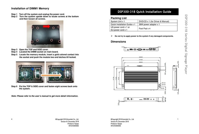
AXIOMTEK DSP300-318 Series User manual