AZZA U694 Series User manual

The
AZZA
U694 MAINBOARD SERIES Page 1
U694BC
U694BX
U694 Mainboard Series
User Manual
SOCKET 370 ATX Mainboard
Version 1.x
UM-U694BXC-E4
Rev 1.0V
Creation Date: 13 September 2001

The
AZZA
U694 MAINBOARD SERIES
Page 2
Copyright
This publication contains information that is protected by copyright. No
part of it may be reproduced in any form or by any means or used to
make any transformation adaptation without prior written permission
from the copyright holders. This publication is provided for informational
purposes only. The manufacturer makes no representations or warran-
ties with respect to the contents or use of this manual and specifically
disclaims any express or implied warranties of merchantability or fitness
for any particular purpose. The user will assume the entire risk of the
use or the results of the use of this document. The manufacturer re-
serves the right to revise this publication and make changes to its con-
tents at any time, without prior notice.
2001. All Rights Reserved.
Trademarks
Microsoft®, MS-DOS®, WindowsTM, Windows® 95 and Windows® 98
are registered trademarks of Microsoft Corporation. PentiumTM III, Cop-
permineTM, TualatinTM and CeleronTM are registered trademarks of Intel
corporation. Award is the registered trademark of Award Software, Inc.
Other trademarks and registered trademarks of products appearing in
this publication are the properties of their respective holders.
Package Checklist
This package contains the following items:
•Mainboard
•Users manual
•One IDE cable
•One 34-pin floppy disk drive cable
•One Driver Utility CD
If any of these items are damaged or missing, please contact your
dealer or sales representative for assistance.
Technical Support
If you require additional information or assistance during installation
please contact your dealer. Your dealer will be able to provide the latest
information.
USER’S NOTICE
USER’S NOTICE
USER’S NOTICE

The
AZZA
U694 MAINBOARD SERIES Page 3
Chapter 1:- Introduction
Page 5
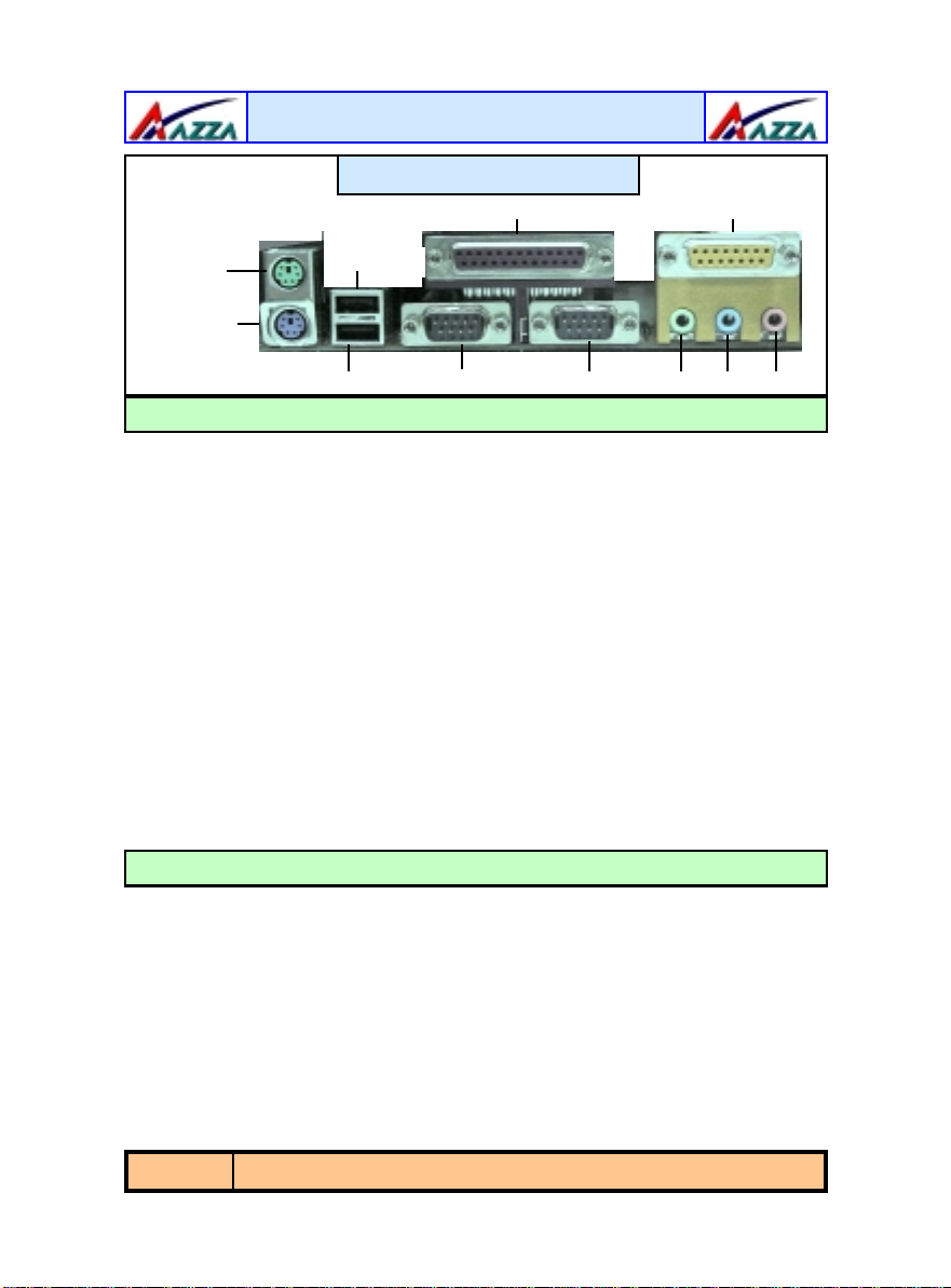
1.1. Mainboard and PC99 ATX External Connector Layout...............................5
1.2. Overview ...................................................................................................6
1.2.1. U694 .....................................................................................................6
1.2.2. Mainboard Dimensions............................................................................6
1.2.3. Environmental Limitations .......................................................................6
1.3. Features and Specifications.......................................................................6
1.4. System Health Monitor Functions..............................................................8
1.4.1. Hardware Monitoring System Utility .........................................................9
1.4.2. Installation.............................................................................................9
1.5. System Intelligence...................................................................................9
Chapter 2:- Hardware Installation
Page 10
2.1. Installation Checklist.................................................................................10
2.2. Installation Steps......................................................................................11
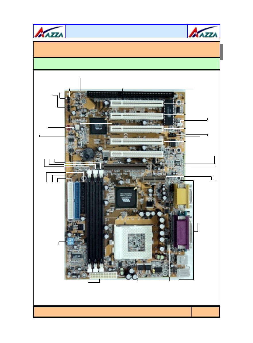
2.3. Expansion Slots, Jumpers and Internal Connectors..................................12
2.4. CPU, Memory and Expansion Slots............................................................13
2.4.1. Installation of the CPU............................................................................13
2.4.2. Memory Modules ....................................................................................13
2.4.3. PCI Slots................................................................................................14
2.4.4. AGP (Accelerated Graphics Port) Slot .......................................................14
2.4.5. AMR (Audio/Modem Riser) Slot ...............................................................15
2.4.6. ISA (Industry Standard Architecture) Slot ................................................ 15
2.5. Internal Connectors...................................................................................15
2.5.1. Floppy Disk Drive (FDD) .........................................................................15
2.5.2. Primary and Secondary IDE Connectors ...................................................15
2.5.3. Standard Infrared Connector...................................................................16
2.5.4. CPU and Chassis Fan Connectors.............................................................16
2.5.5. ATX Power Supply Connector ..................................................................17
2.5.6. WOL (Wake-On-LAN) Connector ............................................................. 17
2.5.7. CD Audio In Connector ........................................................................... 17
2.5.8. USB 3 and USB 4 Connectors ..................................................................18
2.6. System Panel Buttons and LED Connectors...............................................19
2.6.1. PW: Power On/Off and External Suspend Switch Connector ...................... 19
2.6.2. SL LED Connector ..................................................................................19
2.6.3. IDE HDD LED Connector.........................................................................19
2.6.4. Reset Button Connector ..........................................................................20
Table Of Contents
Table Of Contents
Table Of Contents

The
AZZA
U694 MAINBOARD SERIES
Page 4
2.7. Speaker and Power LED Connectors.........................................................20
2.7.1. Speaker Connector ................................................................................ 20
2.7.2. Front Panel Power LED........................................................................... 20
2.8. External Connectors..................................................................................20
2.8.1. PS/2 Keyboard Connector....................................................................... 20
2.8.2. PS/2 Mouse Connector ........................................................................... 21
2.8.3. Serial Port 1 (COM 1) and Serial Port 2 (COM 2) ...................................... 21
2.8.4. Parallel Port Connector (LPT).................................................................. 21
2.8.5. Universal Serial Bus (USB) Port 1 & 2...................................................... 21
2.8.6. Audio/Game Port Connector ................................................................... 21
2.9. Clear CMOS Memory................................................................................22
2.10. DIP Switch...............................................................................................22
Chapter 3:- Managing The PC BIOS
Page 23
3.1. AWARD BIOS CMOS Setup Utility ...........................................................23
3.2. Main Menu...............................................................................................23
3.3. Standard CMOS Setup.............................................................................24
3.4. Advanced BIOS Features.........................................................................26
3.5. Advanced Chipset Features.....................................................................30
3.6. Integrated Peripherals............................................................................33
3.7. Power Management Setup......................................................................36
3.8. PNP/PCI Configuration...........................................................................40
3.9. PC Health Status.....................................................................................41
3.10. Frequency/Voltage Control.....................................................................41
3.11. Load Optimized Defaults.........................................................................42
3.12. Set Supervisor Password ........................................................................43
3.13. Set User Password ..................................................................................44
3.14. Save & Exit Setup/Exit Without Saving..................................................45
Table Of Contents
Table Of Contents
Table Of Contents

The
AZZA
U694 MAINBOARD SERIES Page 5
AMR Slot
AGP Slot
Introduction
Chapter 1
Chapter 1
Chapter 1 -
-
-Introduction
Introduction
Introduction
1.1. Mainboard And PC99 ATX External Connector Layout
ISA Slot
System Panel
And LED
Connectors
Speaker
Power LED
CN 17: Chassis Fan
JP 9 : Clear CMOS
CN 10 : IDE 2
CN 9 : IDE 1
CN 8 : FDC
SW 1: DIP Switch
DIMM 3
DIMM 2
DIMM 1
CN 15: ATX
Power
Connector
CPU
Socket
CN 13: CPU
Fan
PC 99 ATX Connector
CN 21: CD Audio-in
CN 30: USB3
CN 31: USB4
PCI 2 PCI 1
PCI 3PCI 4
PCI 5
CN 16: WOL
CN 12:
IR

The
AZZA
U694 MAINBOARD SERIES
Page 6
CN 1: PS/2 KB
CN 2: PS/2 MS
CN 6: USB 1 CN 3:COM 1 CN 4: COM 2
CN 5: LPT CN18: Game/MIDI Port
SPK-OUT LINE-IN MIC-IN
CN 7: USB 2
1.2.1. The U694 Series
There are two models in this series.
1. U694BC
2. U694BX
1.2.2. Mainboard Dimensions
Width & Length : 305 mm x 195 mm
Height (with retention mechanism): 2.5 inches
PCB Thickness : 4 layers (0.05 inches)
Weight : 18 ounces
1.2.3. Environmental Limitations
Operating Temperature: 10°C to 40°C (50°F to 104°F)
Required Airflow: 50 linear feet per minute across the CPU
Storage Temperature: -40°C to 70°C (-40°F to 158°F)
Humidity: 0 to 90% non-condensing
Altitude: 0 to 10 000 feet
Introduction
PC 99 ATX External Connector
1.2. Overview
Processor
Supports Intel® Socket 370 PentiumTM III Coppermine, TualatinTM or Celeron (0.18μ)
Chipset
The U694 mainboard series supports the VIA VT82C694T (Apollo Pro133T) chipset.
CPU Switching Voltage regulator
These mainboards are equipped with a switching voltage regulator that automatically de-
tects a DC power supply from +1.050V to +1.825V.
1.3. Features and Specifications

The
AZZA
U694 MAINBOARD SERIES Page 7
CPU Front Side Bus Speed Selection (optional for 694BC)
This mainboard comes with an onboard DIP Switch, SW1. SW1 can be used to select the
FSB.
System Memory
These mainboards each have three 168-pin DIMM modules onboard. These modules are
able to support PC-133 and PC-100 SDRAM modules. A maximum memory of 1.5GB is
supported.
Expansion Slots
These mainboards are equipped with five dedicated PCI slots, one 4x AGP slot, one ISA
slot and one AMR slot.
Onboard Audio Features
Supports Microsoft DirectSound/ DirectSound 3D and AC97 Full Duplex.
Word Size
• Data Path: 8-bit, 16-bit, 32-bit, 64-bit
• Address Path: 32-bit
Front Side Bus Frequency (FSB)
FSB frequencies of 66MHz, 100MHz and 133MHz are supported.
BIOS
• Award BIOS, Windows 95/98 Plug and Play (PnP) compatible.
• Supports SCSI sequential boot-up.
• Flash EPROM for easy BIOS upgrades.
• Supports DMI 2.0 function
Desktop Management Interface (DMI)
The mainboard comes with DMI 2.0 built into the BIOS. The DMI utility in the BIOS will
automatically record different information about your system configuration and store this
information in the DMI pool, which is a part of the system board's Plug and Play BIOS.
DMI, along with the appropriately networked software, is designed for easy inventory,
maintenance and the simplified troubleshooting of computer systems.
WOL (Wake-On-LAN) Port
One WOL connector supports Wake-On-LAN functionality.
USB Ports
The mainboard is equipped with 4 USB ports. USB allows data exchange between your
computer and a wide range of simultaneously accessible external Plug and Play
peripherals. USB 1 and USB 2 are external ports. They can be found on the PC 99 ATX
connector. USB 3 and USB 4 are internal connectors that can be used to connect other
USB devices. (Optional cable for two connectors is sold separately)
Introduction

The
AZZA
U694 MAINBOARD SERIES
Page 8
Connectors
•One connector for IrDA interface (optional for U694BC).
•Two IDE connectors.
•One floppy drive interface supports up to two 2.88MB floppy drives.
•One 20-pin ATX power supply connector.
• CPU and chassis fan connectors.
• One CD audio-in connector.
ATX Double Deck Ports (PC 99 color-coded connectors)
•Two USB ports.
•Two external DB-9 serial port connector: COM 1 and COM 2 (UART).
•One SPP/ECP/EPP DB-25 parallel port.
•One mini-DIN-6 PS/2 mouse port.
•One mini-DIN-6 PS/2 keyboard port.
•One game/MIDI port.
•Three audio jacks: speak-out, line-in and mic-in.
PCI Bus Master IDE Controller
•Two PCI IDE interfaces support up to four IDE devices.
•Both models support ATA/33, ATA/66 and ATA100 hard drives.
•PIO Mode 3 and Mode 4 Enhanced IDE (data transfer rate up to 16.6MB/sec.).
•Bus mastering reduces CPU utilization during disk transfer.
•Supports ATAPI CD-ROM, LS-120 and ZIP.
IrDA Interface (optional for U694BC)
The mainboard is equipped with an IrDA connector for wireless connectivity between your
computer and peripheral devices. It supports peripheral devices that meet the HPSIR or
ASKIR standard.
Introduction
The mainboard is capable of monitoring the following health conditions of your system:
1. Processor temperature. It has an overheat alarm.
2. VCORE/2.5V/3.3V/5V/12V voltages and failure alarm.
3. Processor and chassis fan speeds. It has a failure alarm for these fans.
4. Read back capability that displays temperature, voltage and fan speed.
Note: Only use this utility in Windows ® 95 or Windows ® 98 operating systems.
1.4. System Health Monitor Functions

The
AZZA
U694 MAINBOARD SERIES Page 9
Introduction
Dual Function Power Button
Depending on the setting in the Soft-Off By Power-Button field of the Power Management
Setup, this switch allows the system to enter the Soft-Off or Suspend mode.
RTC Timer to Power-on the System
The RTC installed on the system board allows your system to automatically power-on at a
set date and time.
Wake-On-LAN Ready
The Wake-On-LAN function allows the network to remotely wake up a Soft Power Down
(Soft-Off) PC. Your LAN card must support the remote wakeup function. The 5V SB power
source of your power supply must be at least 720mA.
ACPI Ready
The mainboard is designed to meet the ACPI (Advanced Configuration and Power Inter-
face) specification. ACPI has energy saving features that support OS Direct Power Man-
agement (OSPM) for round the clock PC operation.
1.4.1. Hardware Monitoring System Utility
The mainboard comes with the Hardware Monitoring System utility contained on the CD.
It is capable of monitoring the system’s hardware conditions such as the temperature of
the processor, voltage, and the speed of both the CPU and chassis fans. You are allowed
to manually set a range to the items being monitored. If the values are over or under the
set range a warning message will automatically pop up. We recommend that you use the
Default Settings, which are the ideal settings that will maintain the system in a good
working condition.
1.4.2. Installation
To install this utility, please insert the CD into the CD-ROM drive. The auto run screen
(Driver Utility) will automatically appear. Click the Hardware Monitoring button, choose the
chipset, model number and the OS that is installed. Please refer to the CD “Readme” file
1.5. System Intelligence

The
AZZA
U694 MAINBOARD SERIES
Page 10
The following is a checklist of all the expansion slots, jumpers and connectors that should
be configured on your mainboard before you can run your pc.
Hardware Installation
Chapter 2
Chapter 2
Chapter 2 -
-
-Hardware Installation
Hardware Installation
2.1. Installation Checklist
Installation Checklist
Expansion Slots and Sockets
CPU Socket
DIMM Slots
PCI Slots
AGP Slot
AMR Slot
ISA Slot
Socket 370 which supports Intel® PentiumTMIII Celeron or TualatinTM
Three 168 pin slots that supports up to 1.5GB of SDRAM .
Five 32 bit PCI Slots.
One Accelerated Graphics Port Slot
One Audio Modem Riser Slot
One Industry Standard Architecture Slot
Internal Connectors
CN8
CN9
CN10
CN12
CN13
CN15
CN16
CN17
CN21
CN30
CN31
Floppy Disk Drive
Primary IDE
Secondary IDE
Infrared
CPU Fan
ATX Power Supply
Wake On Lan
Chassis Fan
CD Audio In
Universal Serial Bus 3
Universal Serial Bus 4
FDC
IDE1
IDE2
IR
CPU Fan
ATX
WOL
Chassis Fan
CD-In
USB3
USB4
CN1
CN2
CN3
CN4
CN5
CN6
CN7
CN18
PS/2 Keyboard Connector
PS/2 Mouse Connector
Serial Port 1
Serial Port 2
Parallel Port
Universal Serial Port 1
Universal Serial Port 2
Game/Audio Port
PS/2 KB
PS/2 MS
COM1
COM2
LPT
USB1
USB2
Audio/Game
External Connectors

The
AZZA
U694 MAINBOARD SERIES Page 11
You need to complete the following installation steps before you can use your PC.
•Check and Set the Mainboard Settings.
•Install the Central Processing Unit (CPU).
•Install the Memory Modules.
•Install the Expansion Cards.
•Connect the Ribbon Cables, Panel Wires and the Power Supply.
•Setup the system BIOS
Before you start installing your mainboard we strongly recommend
that you use a grounded anti-static mat. We further recommend
that you attach an anti-static wristband, which is grounded at the
same location as the mat, to your wrist.
A Diagram of the Expansion Slots, Jumpers and Connectors can be
seen on the following page
2.2. Installation Steps
Hardware Installation
Installation Checklist (Continued)
System Panel Buttons and LED Connectors
PW
SL
HL
RS
Power On/Off and Suspend Switch Connector.
Standby LED Connector
HDD LED Connector
Reset Button LED Connector
Speaker and Power LED Connector
PWR-LED
SPK Power LED
Speaker Connector
Jumpers
JP9 Clear CMOS

The
AZZA
U694 MAINBOARD SERIES
Page 12
Hardware Installation
CN 31:
USB 4
Speaker
Power LED
ISA Slot
2.3. Expansion Slots, Jumpers and Internal Connectors
CN 9 :IDE1
CN 10:IDE2
CN 21: CD-IN
CN 30:
USB3
PCI 5 PCI 4 PCI 3 PCI 2 PCI 1
CN 17: Chassis Fan
1
System Panel
Buttons and
LED Connectors
1
CN 12: IR
1
DIMM 3
DIMM 2
DIMM 1
JP 9
1
1
CN 16: WOL
1 1
1
1
AMR Slot
AGP Slot
CN 13: CPU Fan
1
CN 15: ATX Power
SW 1: DIP
Switch
CN 8: FDC

The
AZZA
U694 MAINBOARD SERIES Page 13
2.4.1. Installation of the CPU
To install your processor, please complete the following set of instructions
1. Locate a small dot marked on the top of the CPU. This mark indicates Pin 1 of
the CPU.
2. Locate Pin 1 for the Socket on the mainboard.
3. There is a lever on the side of the socket. First push this lever sideways and
then lift it to a 90-degree angle.
4. Insert the CPU into the Socket. Please make sure that Pin 1 for the CPU is in-
serted into Pin 1 of the Socket.
5. When the CPU is installed correctly push the lever back into place.
6. Install a proper heat sink with cooling fan for proper heat dissipation.
Failing to install a heat sink with cooling fan may cause overheating which will
burnout your CPU and damage your mainboard.
2.4.2. Memory Modules
These mainboards all have three 168-pin DIMM slots and are able to support a maximum
memory of 1.5 GB. The DIMM slots are located on the right hand side of the board. To
install the DIMM’s into these slots, make sure the white lever at each side of the slot has
been pulled down to an angle of approximately 45°. Make sure that the DIMM is in the
correct orientation. Place the DIMM on the slot and push down firmly.The white levers will
come back up and lock the module in place.
Important: The DIMM’s can only be fitted into the slots in one orientation.
Make sure that the DIMM’s are in the correct orientation and the pins are cor-
rectly aligned before you insert them.
Hardware Installation
2.4. CPU, Memory and Expansion Slots
Top View of a 168-pin DIMM Slot
IMPORTANT: CPU COOLING FAN
Please ensure that you have an approved heat sink with cooling fan. Without a
proper heat sink with cooling fan you will damage both the mainboard and the
CPU.

The
AZZA
U694 MAINBOARD SERIES
Page 14
NOTE: “Out Of Memory” Error Message
If you have installed more than 512 MB of RAM and are running Microsoft Windows Millennium Edition,
Windows 98 Second Edition, Windows 98 or Windows 95 you may experience memory problems. Two
symptoms ofthese problems are being unable to run anMS-DOS session while youare running Windows or
the computer maystop responding whileWindows is starting.
Thereare three possible solutions to thisproblem:
1) Reduce the amountof memory Vcache uses to 512 MB or less byaltering the MaxFileCache setting in
the System.ini file.
2) Use the System Configuration Utility to reduce the amount of memory Windows uses to 512 MB or
less.
3) Reduce the memory installed on your computer to 512 MB or less.
This problem can also occur if youare using an AdvancedGraphic Port(AGP) video adapter.
2.4.3. PCI Slots
These boards come with five PCI slots. They are located on the left hand side of the
board. Both PCI and PCI expansion cards may require IRQ’s. This mainboard complies
with Plug and Play (PnP) specifications. Whenever a PnP compliant card is added the sys-
tem will automatically be configured and the IRQ’s will be assigned automatically.
When you are inserting your PCI card make sure that the pins are correctly aligned. When
the pins are properly aligned with the hole’s in the slot, push down gently.
11 pins 49 pins
2.4.4. AGP (Accelerated Graphics Port) Slot
AGP is a dedicated bus slot. It operates at 66 MHz and transfers data at a rate up to 106
MB/s. This allows 3D applications to run more smoothly. The U694 mainboards each come
with one AGP slot. These slots are able to support 1x, 2x and 4x AGP cards.
66 pins
Hardware Installation
Top View of PCI Slot
Top View of an AGP Slot

The
AZZA
U694 MAINBOARD SERIES Page 15
Hardware Installation
2.5.1. Floppy Disk Drive (FDD)
Connector: CN 8
Type: 34 pin block
The FDD connector can support two Floppy drives. It is located at the front of the main-
board. To connect, use the ribbon-cable that has been provided. Make sure that the red
strip is connected to PIN 1 of the connector.
2.4.5. AMR (Audio/Modem Riser) Slot.
An AMR card is a small board that can be plugged directly into the onboard AMR slot. It
packages analog I/O audio functions with a codec chip. The codec chip converts back and
forth from analog to digital.
Top View of an AMR Slot
11 pins 12 pins
2.4.6. ISA (Industry Standard Architecture) Slot
ISA is a widely compatible 8-bit and 16-bit onboard bus.
Top View of an ISA Slot
18 pins 31 pins
2.5. Internal Connectors
Top View of a Floppy Disk Drive
Connector PIN 1
2.5.2. Primary and Secondary IDE connectors
Connector: CN 9 (primary)/ CN 10 (secondary)
Type: 40 pin blocks
The U694 mainboards all have two IDE connectors: a primary and secondary. Each IDE
connector can support two IDE drives. These mainboards can therefore support up to four
IDE devices each. If you install two hard drives, you need to configure the second drive to
slave mode in the BIOS setup
.
Please refer to your hard drive manual for the appropriate
jumper settings.
17 Pins

The
AZZA
U694 MAINBOARD SERIES
Page 16
Fan Signal +12V DC
Ground
1 Ground
2 +12V DC
3 Fan Signal
Top View of a Fan Connector Front View of a Fan Connector
Hardware Installation
2.5.3. Standard Infrared Connector (Optional for U694BC)
Connector: CN 12
Type: 5 pin
The SIR connector supports an optional wireless transmitting and receiving module. You
must configure UART 2 to select whether UART 2 is directed for use with COM 2 or IrDA.
2.5.4. CPU Fan and Chassis Fan Connector
Connector: CN 13 (CPU Fan)/CN 17 (Chassis Fan)
Type: 3 pin
The cooling fans must be connected to their respective power connectors. If you have
installed the hardware-monitoring feature you will be able to monitor the rotating speed
of the CPU cooling fan in your Windows operating system.
Top View of an IDE
Connector
20 PINS
PIN 1
1 5V DC
2 No Connection
3 IR Reciever
4 Ground
5 IR Transmitter
Top View of an IR Connector
5V DC
IR Receiver Ground IR Transmitter
Front View of an IR Connector

The
AZZA
U694 MAINBOARD SERIES Page 17
2.5.7. CD Audio-in Connector
Connector: CN 21
Type: 4 pin un-housed
This mainboard has one CD Audio-in connectors. This connector is used to connect the CD
ROM audio out.
Hardware Installation
2.5.5. ATX Power Supply Connector
Connector: CN 15
Type: 20 pin block
This must be connected to an ATX power supply.
The plug from the power supply can only be in-
serted in one orientation. Make sure the pins are
correctly aligned. Find the correct orientation and
push the plug down firmly.
2.5.6. WOL (Wake On LAN) Connector
Connector: CN 16 (WOL)
Type: 3 pin
The WOL connector must be connected to a LAN card that has Wake-On-LAN (WOL) out-
put. This connector powers up the system when a wakeup packet or signal is received
through the LAN card.
In order to use the WOL LAN card or the modem to trigger the power on the PC system,
the switching power supply must have the ability to provide a driving current of at least
720 mA and be connected to a “5V standby” voltage.
ATX Power Supply Connector
Pin 1 Pin 11
+12V
5VSB
PWR_OK
GND
+5VDC
GND
+5VDC
GND
+3.3VDC
+3.3VDC
+5VDC
+5VDC
-5VDC
GND
GND
GND
PS_ON#
GND
-12VDC
+3.3VDC
WOL
5V_SB
Ground
1 5V_SB
2 Ground
3 WOL
Top View of a WOL Connector Front View of a WOL Connector

The
AZZA
U694 MAINBOARD SERIES
Page 18
Hardware Installation
Right Channel
Audio In
Left Channel
Audio In Ground
1 Left Channel Audio In
2 Ground
3 Ground
4 Right Channel Audio In
Top View of a CD Audio In
Connector Front View of a CD Audio In
Connector
2.5.8. USB 3 and USB 4 Connectors
Connector: CN 30 (USB 3)/CN31 (USB 4)
Type: 5 pin / 5 pin
You already have two USB ports available, USB 1 and 2 (see external connectors). USB3
and USB4 connectors allow you to add on an optional kit to expand the total number of
USB ports available. These connectors allow you to use an extra 2 USB devices.
Note: These are not the standard USB connectors you find on the ATX PC99 connector.
To connect USB devices you need to use an expansion cable (purchased separately) that
ends in a standard USB connector. Ask your retailer for more details.
5V DC
Ground
Ground Data -
Data +
1 5V DC
2 Data-
3 Data+
4 Ground
5 Ground
Top View of a USB Port Front View of a USB Port

The
AZZA
U694 MAINBOARD SERIES Page 19
Hardware Installation
2.6.1 PW: Power On / Off and External Suspend Switch Connector
The Power On/Off connector has two functions. It can be the Power Switch or Suspend
Switch of your PC system. You can either choose “Delay 4 Sec” or “Instant
OFF” (Please refer to the Award BIOS setup instructions in Chapter 3).
Option 1: If you choose “Delay 4 Sec.” In the BIOS CMOS Setup, the function of “PW”
will be:
A. When the system power is "OFF", press this switch, the system will power on.
B. When system power is "ON”, you can select two different modes: -
Mode 1: Press and hold the Power ON button for less than 4 seconds and then release it.
The system will be turned into Suspend mode (turned into the GREEN mode) When the
system is in the Suspend mode:-
!""Press the Power on button (less than 4 seconds), the system will return to Full-ON
mode.
!""Press and hold the Power On Button for more than 4 seconds, the system will be
powered off.
Mode 2: Press and hold the Power ON button for more than 4 seconds, the system will
be completely powered off.
Option 2: If you choose “Instant OFF.” In the BIOS CMOS Setup, the power switch will
operate like a normal ON / OFF Power button.
2.6.2. SL LED Connector
When the AC power is “ON” the mainboard will always have a standby voltage of +5V and
the SL LED will be on. If this LED is off it means that the AC power is “OFF” or has been
disconnected or Full on.
2.6.3. IDE HDD LED Connector
Any read and write activity by the HDD will turn this LED on.
Ground
The following System Panel Buttons and LED
Connectors can be found at the front of the
mainboard on the left hand side.
PW= Power On/Off and
Suspend Switch Connector
SL = Standby LED Connector
HL = HDD LED Connector
RS = Reset Button Connector
2.6. System Panel Buttons and LED Connectors PIN 1
SL:Standby DC pull up
HL: +5V DC Pull Up Ground
RS: Reset Control
PW:+5V DC Pull Up Ground
Ground
Top View of the System Panel
and LED Connectors
This manual suits for next models
2
Table of contents
Other AZZA Motherboard manuals