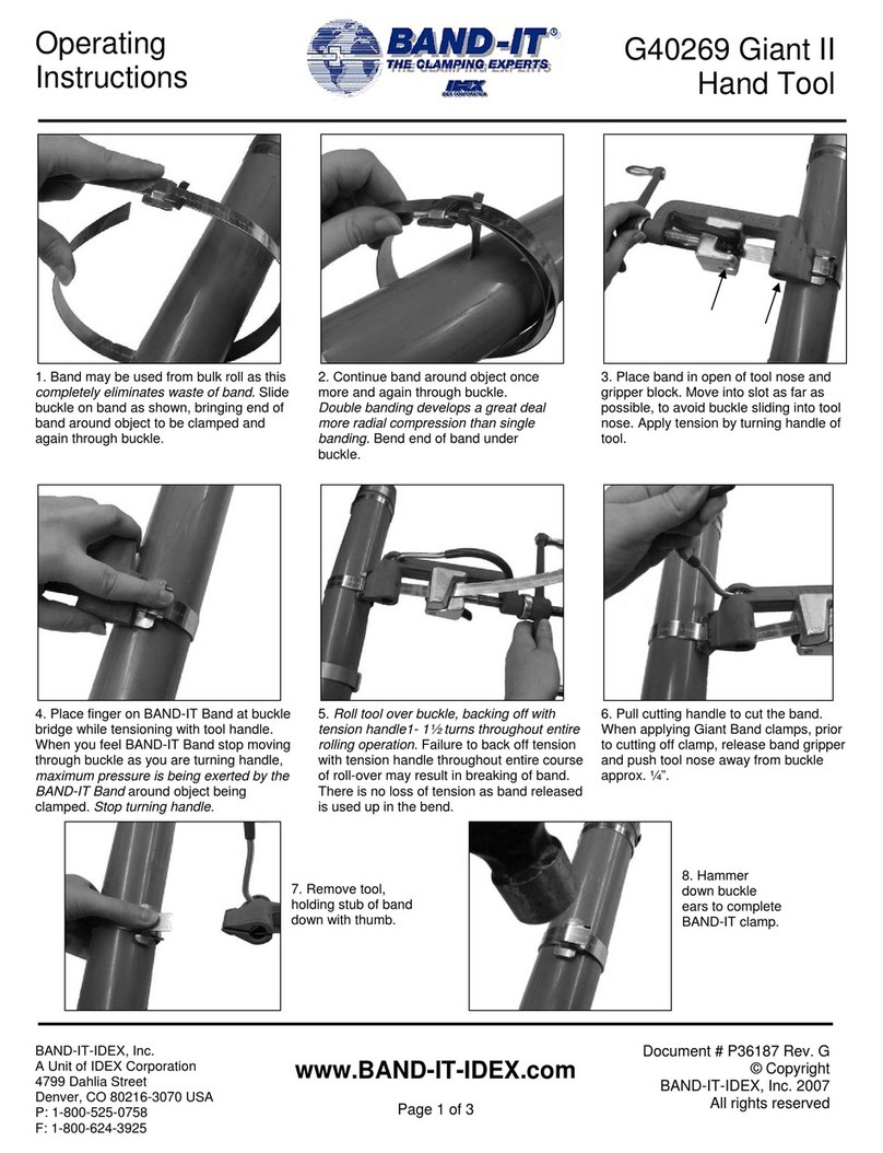
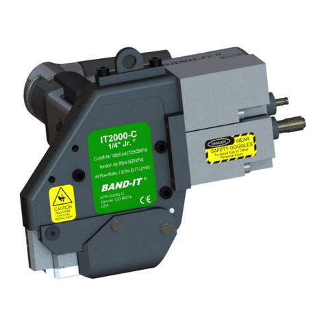
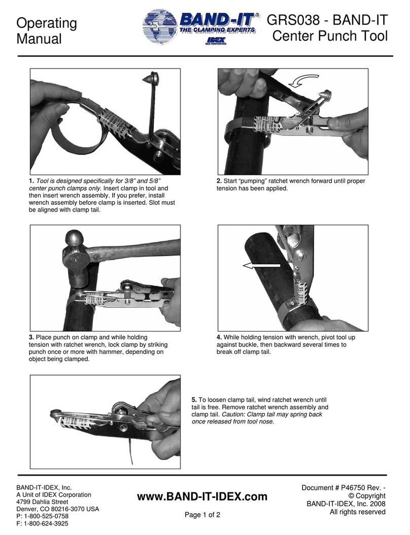
Band-it IT8000 User manual

1
User Manual
IT8000
3/8” Tie-Lok® Data Tool
Document #P80080 Rev. B
© Copyright
BAND-IT-IDEX, Inc. 2022
All rights reserved
All rights reserved
BAND-IT-IDEX, Inc.
A Unit of IDEX Corporation
4799 Dahlia Street
Denver, CO 80216-3070 USA
P: 1-800-525-0758
IT8000 User Manual
Original document
(Not a translation)

2
User Manual
IT8000
3/8” Tie-Lok® Data Tool
Document #P80080 Rev. B
© Copyright
BAND-IT-IDEX, Inc. 2022
All rights reserved
All rights reserved
BAND-IT-IDEX, Inc.
A Unit of IDEX Corporation
4799 Dahlia Street
Denver, CO 80216-3070 USA
P: 1-800-525-0758
TABLE OF CONTENTS
SAFETY GUIDELINES AND WARRANTY.................................................................................................4
SAFETY INSTRUCTIONS...........................................................................................................................................4
WARRANTY.............................................................................................................................................................4
SAFETY SIGNS..........................................................................................................................................................5
GUARDING AND INTERLOCKS.................................................................................................................................6
PRODUCT SAFETY LOCATIONS................................................................................................................................7
OVERVIEW.........................................................................................................................................8
QUICK START OVERVIEW........................................................................................................................................8
ENVIRONMENT..................................................................................................................................9
TRANSPORTATION, STORAGE, HANDLING .............................................................................................................9
TOOL SETUP.....................................................................................................................................10
OPERATING REQUIREMENTS............................................................................................................................... 10
PART DESCRIPTIONS AND LOCATIONS ................................................................................................................ 11
INSTALLATION TOOL DIMENSIONS...................................................................................................................... 13
CONTROLLER ENCLOSURE DIMENSIONS............................................................................................................. 14
CONNECTING THE TOOL TO CONTROLLER.......................................................................................................... 15
CONNECTING THE HMI TO CONTROLLER............................................................................................................ 16
AIR SYSTEM SETUP AND PRESSURE SETTINGS .................................................................................................... 17
AIR FLOW TIMING................................................................................................................................................ 18
FACTORY PROGRAM SETTINGS ........................................................................................................................... 31
SYNCING TOOL TO CONTROLLER......................................................................................................................... 19
OPERATION .....................................................................................................................................20
TIE INSTALLATION PROCEDURE........................................................................................................................... 20
TOOL OPERATION................................................................................................................................................ 20
TIE INSPECTION ................................................................................................................................................... 21
CLAMP PLACEMENT ............................................................................................................................................ 21
MOUNTING AND FIXTURING............................................................................................................................... 22
TOOL ROTATION.................................................................................................................................................. 25
CENTER OF GRAVITY............................................................................................................................................ 26
MOUNTING EXAMPLES........................................................................................................................................ 27
3
User Manual
IT8000
3/8” Tie-Lok® Data Tool
Document #P80080 Rev. B
© Copyright
BAND-IT-IDEX, Inc. 2022
All rights reserved
All rights reserved
BAND-IT-IDEX, Inc.
A Unit of IDEX Corporation
4799 Dahlia Street
Denver, CO 80216-3070 USA
P: 1-800-525-0758
HARNESS ROUTING.............................................................................................................................................. 28
TOOL CLEARANCE REQUIREMENTS..................................................................................................................... 29
SENSOR ACTIVATION........................................................................................................................................... 30
REMOTE ACTUATION........................................................................................................................................... 30
CUT-OFF SIGNAL.................................................................................................................................................. 30
SOFTWARE AND ELECTRONICS .........................................................................................................32
HMI OVERVIEW ................................................................................................................................................... 32
MAINTENANCE ................................................................................................................................39
MAINTENANCE SCHEDULE .................................................................................................................................. 39
LUBRICATION....................................................................................................................................................... 40
TENSION WHEEL CLEANING ................................................................................................................................ 41
KNIFE REPLACEMENT........................................................................................................................................... 42
HEAD REPLACEMENT........................................................................................................................................... 43
PUNCH REPLACEMENT ........................................................................................................................................ 44
TENSION AND BACKING WHEEL REPLACEMENT................................................................................................. 45
TROUBLESHOOTING.........................................................................................................................46
ERROR CODES...................................................................................................................................................... 49

4
User Manual
IT8000
3/8” Tie-Lok® Data Tool
Document #P80080 Rev. B
© Copyright
BAND-IT-IDEX, Inc. 2022
All rights reserved
All rights reserved
BAND-IT-IDEX, Inc.
A Unit of IDEX Corporation
4799 Dahlia Street
Denver, CO 80216-3070 USA
P: 1-800-525-0758
SAFETY GUIDELINES AND WARRANTY
SAFETY INSTRUCTIONS
Read this manual to help you understand the intent and operation of this tool prior to installing BAND-IT Tie-Lok
® ties.
oThis product manual contains detailed instructions for setting up the tool and safely
installing ties.
oAlways wear safety glasses and appropriate gloves when operating this tool.
oKeep hands away from tool head and clamp while operating.
oCare should be taken to ensure fingers are not in the way of the clamp being applied.
oMaintain the tool by following the scheduled preventative maintenance interval provided in
this document.
oNever use this product for anything other than its original intended purpose.
IMPORTANT:
oThe object clamped and the 3/8 " Tie-Lok® tie must be compatible with each other and the
environment in which the final product will be used.
oAlways disconnect from air and electrical power sources before performing maintenance.
The IT8000 tool is designed for use with BAND-IT 3/8 " Tie-Lok® ties only. Accordingly, BAND–IT–IDEX, Inc.
makes no representations with respect to the compatibility of these tools when used with non-BAND-IT or any
other incompatible clamps.
WARRANTY
For warranty information go online at:
https://www.band-it-idex.com/en/terms-conditions
Save these instructions for future use.

5
User Manual
IT8000
3/8” Tie-Lok® Data Tool
Document #P80080 Rev. B
© Copyright
BAND-IT-IDEX, Inc. 2022
All rights reserved
All rights reserved
BAND-IT-IDEX, Inc.
A Unit of IDEX Corporation
4799 Dahlia Street
Denver, CO 80216-3070 USA
P: 1-800-525-0758
This equipment has been tested by BAND-IT-IDEX and meets the requirement of stability during use, storage
conditions, transportation, assembly, dismantling when out of service, testing or foreseeable breakdowns
providing that the proper safety precautions are observed.
DANGER—Misuse of this equipment may result in serious injury to personnel.
•Only use the equipment for its intended purpose, as described in this manual
•Do not attempt to operate the equipment with covers removed
•Refer to the installation section before installing machine
•Do not operate machine with wet hands
Please read this entire manual before unpacking, setting up or operating this equipment. Pay attention to all
danger and caution statements. Failure to do so could result in serious injury to the operator or other
personnel, or damage to the equipment.
SAFETY SIGNS
High Voltage –Risk of electric shock
Pinch Point –Refer to accompanying documents
Caution –Refer to accompanying documents
It is the task of the employer to warn his or her staff of risks, to train them on prevention of accidents, and to
provide necessary safety equipment and devices for the operator’s safety.
Before starting to work with the machine, the operator should check the features of the machine and learn all
details of the machine’s operation. The machine should only be operated by staff members who have read and
understand the contents of this manual.

6
User Manual
IT8000
3/8” Tie-Lok® Data Tool
Document #P80080 Rev. B
© Copyright
BAND-IT-IDEX, Inc. 2022
All rights reserved
All rights reserved
BAND-IT-IDEX, Inc.
A Unit of IDEX Corporation
4799 Dahlia Street
Denver, CO 80216-3070 USA
P: 1-800-525-0758
Figure 1
GUARDING AND INTERLOCKS
Safeguards:
•Main Tool Housing: Covers primary mechanical body and actuators to prevent pinching during operation
•Head cover: Covers the mechanical head piece of the tool to prevent pinching during cutoff process
•Circuit breaker: Housed inside main enclosure.
•Power cord: Main method of removing power to unit. Unplug from wall or main enclosure.
Interlocking functions and features:
•The tool is not intended to operate without guards in place. The tool does not have any interlock
functions or features that prevent operation if the guards are missing or enclosures are open. It
is the responsibility of the user to provide safety interlocks if required.
Securing machine for safe maintenance:
•The tool must have all power and compressed air sources removed before service.
•All guards must be replaced, and enclosures closed before power and air sources are
reconnected to the unit.
•Before preventive maintenance, disconnect device from wall. The appliance plug is the
disconnect device.
•The Device comes with an emergency stop (E-Stop button)
E-Stop

7
User Manual
IT8000
3/8” Tie-Lok® Data Tool
Document #P80080 Rev. B
© Copyright
BAND-IT-IDEX, Inc. 2022
All rights reserved
All rights reserved
BAND-IT-IDEX, Inc.
A Unit of IDEX Corporation
4799 Dahlia Street
Denver, CO 80216-3070 USA
P: 1-800-525-0758
PRODUCT SAFETY LOCATIONS
Warning:
Do not place fingers, hands,
or any body parts under the
cutting head while tool is
running
Warning:
Do not place fingers,
hands, or any body parts
near the outlet of the tail
eject while tool is running
Figure 2
Figure 3

8
User Manual
IT8000
3/8” Tie-Lok® Data Tool
Document #P80080 Rev. B
© Copyright
BAND-IT-IDEX, Inc. 2022
All rights reserved
All rights reserved
BAND-IT-IDEX, Inc.
A Unit of IDEX Corporation
4799 Dahlia Street
Denver, CO 80216-3070 USA
P: 1-800-525-0758
OVERVIEW
•The IT8000 is designed to install 3/8" Tie-Lok® ties with repeatability and control. The machine is
adjustable for individual applications and provides data to ensure the quality of the finished assembly
•The IT8000 is powered by pneumatic cylinders and an electric motor powered with an AC connection.
Data is transferred from tool to controller (Siemens PLC) and can be extracted utilizing USB or ethernet
•The mechanical drive portion of the tool tensions, dimples, and cuts a clamp to form a durable and
strong fastened joint between two objects
•The electronic control of the tool uses feedback from the mechanical portion to accurately control the
tension process of the tool and activate the punch and cut
•The tool can be programmed by the user to accommodate specific applications utilizing the HMI
(Human-Machine Interface)
•The tool can provide a data output to allow for verification of the integrity of the finished assembly
QUICK START OVERVIEW
1. Connect data and motor cable to tool (Page 15)
Note: Ensure controller power and air are off before connecting to the tool (Page 16)
2. Connect data cable to controller (Page 16)
3. Connect air harness to tool (Page 15) and controller (Page 17, Fig. 20)
4. Connect HMI (touchscreen) to controller (page 16)
5. Connect external regulator to controller (page 16)
6. Connect air hose to external controller regulator (page 17)
Customer supplied: connect with either 3/8”OD push-to-connect fitting or ¼” NPT thread
7. Plug in controller (110V US standard outlet)
8. Power on tool, ensure door latch is set to “On” and flip power switch on outlet module (Page 16)
Note: If the controller is not getting power, ensure the internal circuit breaker is flipped on
9. HMI will boot up main program screen
10. Enter tool serial number, located by the three mounting holes (Page 19)
11. Tool settings are factory set to recommended settings for .019” band thickness (punch pressure)
1. Ensure all settings are correct for application (page 31) and input settings as necessary
1. Set punch pressure (Page 17)
2. Set tension torque (Page 31)
3. Set error passcode preference (Page 38)
8. Message banner at top of screen should read "Tool Ready" and the tool is ready to use (if trigger is
unresponsive press the "Reset Error" button on the HMI)
Note: The controller needs approximately 30 seconds to boot up before the trigger is responsive

9
User Manual
IT8000
3/8” Tie-Lok® Data Tool
Document #P80080 Rev. B
© Copyright
BAND-IT-IDEX, Inc. 2022
All rights reserved
All rights reserved
BAND-IT-IDEX, Inc.
A Unit of IDEX Corporation
4799 Dahlia Street
Denver, CO 80216-3070 USA
P: 1-800-525-0758
ENVIRONMENT
TRANSPORTATION, STORAGE, HANDLING
Table 1
Transportation
Avoid shocks and vibration
Immediately check units for transport damage
and inform your transport company, if necessary
If possible, ship in original packaging
Storage
Store unit in a clean, dry place with air
temperature between -25°C and +55°C (-13°F to
131°F)
Handling
Use techniques appropriate for lifting and moving
heavy objects.
Normal operating conditions are defined as:
For Indoor Use ONLY
Temperature range from 5°C to 40°C (41°F to 95°F).
Max relative humidity 80% for temperatures up to 31°C (88°F), decreasing linearly to 50% at 40°C (104°F).
Conforms to Applicable RATED POLLUTION DEGREE 1.
Correct illumination for safety of operator (ISO 8995-89).
Avoid using the tool near equipment with strong EMI / RFI emission.
Avoid using the tool near equipment susceptible to EMI / RFI interference.
This tool has been tested for:
Altitude: Sea level to 5690 ft (1730 m)
Atmospheric pressure: 14.7 lbs/in2 (1 Kg/cm2) to 12 lbs/in2(0.85 Kg/cm2)
Tool size:
Tool only: 12” L x 6.5” W x 8” H (305 x 165 x 203 mm)
Controller box: 20” x 20” x 10” (508 x 508 x 254 mm)
Tool weight: 10 lbs (4.5 kg)
Controller weight: 63 lbs (28.6 kg)

10
User Manual
IT8000
3/8” Tie-Lok® Data Tool
Document #P80080 Rev. B
© Copyright
BAND-IT-IDEX, Inc. 2022
All rights reserved
All rights reserved
BAND-IT-IDEX, Inc.
A Unit of IDEX Corporation
4799 Dahlia Street
Denver, CO 80216-3070 USA
P: 1-800-525-0758
TOOL SETUP
OPERATING REQUIREMENTS
Table 2
Clamp Type
BAND-IT 3/8” Tie-Lok® Tie Series
Operation Air Requirements
80 PSI (552 kPa) Clean dry compressed air
Air Flow Rate: 0.25 CFM (7.1 L/min.)
Do not exceed pressure listed on regulator
assembly
Power requirements
110-230 Volts 50-60 Hz Grounded AC 4 A Max
Human-Machine Interface (HMI)
Programmable Color Touchscreen
Emergency Stop
Application of emergency stop button will stop
electric motor and open all valves, removing air
pressure from pneumatic cylinders.

11
User Manual
IT8000
3/8” Tie-Lok® Data Tool
Document #P80080 Rev. B
© Copyright
BAND-IT-IDEX, Inc. 2022
All rights reserved
All rights reserved
BAND-IT-IDEX, Inc.
A Unit of IDEX Corporation
4799 Dahlia Street
Denver, CO 80216-3070 USA
P: 1-800-525-0758
PART DESCRIPTIONS AND LOCATIONS
Clamp
Cylinder
Pinch Arm
Upper
Band
Guide
Lower Band
Guide
Backing
Wheel
Punch
Punch
Holder
Trigger Link
Tension Wheel
Punch
Cylinder
Trigger
Trigger
Cylinder
Cut
Straight
Link
Tool Head
Tangency
and Buckle
Sensors
Cut-off
Cylinder
Frame
Cut-off Cylinder Mount
Plate (Serial Number
Located here)
Drive
shaft
Knife
Cutter Arm
Cut
Link
Figure 5
Figure 4

12
User Manual
IT8000
3/8” Tie-Lok® Data Tool
Document #P80080 Rev. B
© Copyright
BAND-IT-IDEX, Inc. 2022
All rights reserved
All rights reserved
BAND-IT-IDEX, Inc.
A Unit of IDEX Corporation
4799 Dahlia Street
Denver, CO 80216-3070 USA
P: 1-800-525-0758
PART DESCRIPTIONS CONT.
Right
Cover
Pneumatics
Cover
Head
Cover
Handle
Cover
Left Side
Cover
Figure 6

13
User Manual
IT8000
3/8” Tie-Lok® Data Tool
Document #P80080 Rev. B
© Copyright
BAND-IT-IDEX, Inc. 2022
All rights reserved
All rights reserved
BAND-IT-IDEX, Inc.
A Unit of IDEX Corporation
4799 Dahlia Street
Denver, CO 80216-3070 USA
P: 1-800-525-0758
INSTALLATION TOOL DIMENSIONS
Figure 7
Figure 8

14
User Manual
IT8000
3/8” Tie-Lok® Data Tool
Document #P80080 Rev. B
© Copyright
BAND-IT-IDEX, Inc. 2022
All rights reserved
All rights reserved
BAND-IT-IDEX, Inc.
A Unit of IDEX Corporation
4799 Dahlia Street
Denver, CO 80216-3070 USA
P: 1-800-525-0758
CONTROLLER ENCLOSURE DIMENSIONS
Figure 9
The controller box is
designed to be mounted
with (4) 9/16” holes on the
back mounting plate.

15
User Manual
IT8000
3/8” Tie-Lok® Data Tool
Document #P80080 Rev. B
© Copyright
BAND-IT-IDEX, Inc. 2022
All rights reserved
All rights reserved
BAND-IT-IDEX, Inc.
A Unit of IDEX Corporation
4799 Dahlia Street
Denver, CO 80216-3070 USA
P: 1-800-525-0758
Figure 12
Figure 10
Figure 11
CONNECTING THE TOOL TO CONTROLLER
This tool requires both electricity and compressed air to operate. Provisions must be made to deliver both to the
tool in a safe manner. The tool can be plugged in a standard 110V outlet.
Connect the data cable to the main tool housing. Ensure that the key is aligned before attempting to screw
down the connection (Fig. 10). Each electrical connector has a unique interface, do not attempt to force a plug
into a connector if the receptable does not match or the key is misaligned.
Connect the motor cable to the motor. Align the two arrows on cable and connector and then rotate a quarter
turn (fig. 11).
The tool includes an air harness with six ¼” (6.35mm) outside diameter tubes pre-assembled to quick-connect
ends. Attach one end to the controller and the other end to the tool connection point, taking care to align keys
before insertion. Once inserted, twist coupling until it is tight on the connector.
Only plug in the power cable to the controller after all the other connections have been completed. The power
entry module includes the ON/OFF switch. The power cable provided with the tool is standard grounded plug
compatible with North America outlets.
Data Cable
Air Harness
Motor Cable
Data Cable Key
Motor Key

16
User Manual
IT8000
3/8” Tie-Lok® Data Tool
Document #P80080 Rev. B
© Copyright
BAND-IT-IDEX, Inc. 2022
All rights reserved
All rights reserved
BAND-IT-IDEX, Inc.
A Unit of IDEX Corporation
4799 Dahlia Street
Denver, CO 80216-3070 USA
P: 1-800-525-0758
Figure 15
Figure 16
Figure 14 - HMI
Figure 13
CONNECTING THE HMI AND REGULATOR TO CONTROLLER
The connection to the HMI (Human-Machine Interface) (Fig 14) is hardwired, so the green HMI cable only needs
to be connected to the controller. To connect the HMI cable to the controller, align the red dots and press the
connector in (fig. 13) On the side of the HMI is a USB port that can be used to transfer tool data. The system
regulator has two connections that must be connected (Fig.17). Each electrical connector has a unique interface,
do not attempt to force a plug into a connector if the receptable does not match or the key is misaligned.
The controller has inputs for a Pass/Fail “cutoff signal” and remote actuation to operate the tool hands free.
These do not need to be connected to run the tool in normal operation.
The controller has multiple switches. The I/0 power switch above the plug and the door latch function the same,
cutting all power and air to the controller. The E-stop on the top of the box removes air from the tool and power
to the motor. The HMI will remain on.
Figure 17
HMI Cable
Connector
E-Stop
Door Latch
Power Switch
Ethernet Port
Cable
Connections
Bank
Pneumatics
Valve Bank
Cut-off Signal &
Remote Trigger
Data Cable
HMI Key
Regulator
Connections

17
User Manual
IT8000
3/8” Tie-Lok® Data Tool
Document #P80080 Rev. B
© Copyright
BAND-IT-IDEX, Inc. 2022
All rights reserved
All rights reserved
BAND-IT-IDEX, Inc.
A Unit of IDEX Corporation
4799 Dahlia Street
Denver, CO 80216-3070 USA
P: 1-800-525-0758
Figure 20
Figure 19
AIR SYSTEM SETUP AND PRESSURE SETTINGS
Table 3 - Recommended Pressure Settings:
Caution: Pressures above the specified settings may cause premature clamp failure and/or tool wear.
Use the external regulators to adjust the air pressure on the tool. The system pressure regulator is in-line with
the Input Air line (Fig 16). It has two connectors that much be attached to power and read the regulator. The
punch pressure regulator is in-line with Punch Extend line (Fig. 19). The punch must be extended to read the
pressure. The punch pressure reading is shown on the manual screen. (pg. 33). The regulators are adjusted
independently. Note that the HMI pressure limits may need to be updated as well (pg. 36), but the pressure
cannot be adjusted in the HMI. The regulator has a 3/8” OD push-to connect fitting on it. If a different style of
fitting is preferred to connect to the input regulator, the fitting can be removed and replaced with a different
¼” NPT fitting.
The controller and tool harness air-line valve numbering is shown below.
Tie Thickness
(in)
Punch Pressure
(psi)
System Pressure
(psi)
0.019
65 ± 2
80 ± 5
0.024
80 ± 2
80 ± 5
Valve Position
Actuator
1
Punch Extend
2
Cut Extend
3
Trigger Extend
4
Clamp Extend
5
Punch Retract
6
Cut Retract
2
1
4
Exhaust
Input
Air
Controller Pneumatics Valve
Bank
Exhaust
3
6
Unused
5
Figure 18
Tool Air Harness
Table 4

18
User Manual
IT8000
3/8” Tie-Lok® Data Tool
Document #P80080 Rev. B
© Copyright
BAND-IT-IDEX, Inc. 2022
All rights reserved
All rights reserved
BAND-IT-IDEX, Inc.
A Unit of IDEX Corporation
4799 Dahlia Street
Denver, CO 80216-3070 USA
P: 1-800-525-0758
AIR FLOW TIMING
The following chart shows the cylinder actuation for one complete tie install.
*Scrap Ejection: If the automatic ejection setting is ON (recommended), the tail scrap will be automatically
released from the tension wheels after the cut operation to ease in pulling out scrap. Otherwise, the tool will
wait for the next trigger press to eject scrap. Note: Regardless of the setting, the scrap will have to be pulled out
by hand. See HMI settings to change the setting (pg. 35)
Event description
Tool ready
for next tie
Engage
gripper
Tension
clamp /
engage
punch
cylinder
Actuate
trigger to
dimple
Retract
punch
Reset
trigger
Cut-off
Eject
Timing / duration
At rest
Entire
duration of
tensioning
tie and
ejecting
scrap
Entire
duration of
tightening
tie
Immediately
after
sensors are
activated
60 ms
(Punch
Extend
Duration)
Immediately
after punch
retract
150 ms (Cut
Retract
Delay)
Auto Eject
Only*
(0.5 s)
Clamp cylinder
Extend
Punch cylinder
Extend
Retract
Trigger cylinder
Extend
Cut-off cylinder
Extend
Retract
Pressurize
Exhaust
Figure 21

19
User Manual
IT8000
3/8” Tie-Lok® Data Tool
Document #P80080 Rev. B
© Copyright
BAND-IT-IDEX, Inc. 2022
All rights reserved
All rights reserved
BAND-IT-IDEX, Inc.
A Unit of IDEX Corporation
4799 Dahlia Street
Denver, CO 80216-3070 USA
P: 1-800-525-0758
Figure 22
SYNCING TOOL TO CONTROLLER
How to connect or replace an existing tool to the controller:
1. Activate E-stop or turn controller off to disable air and power to motor.
2. Disconnect data and motor cable to current tool (only required if a tool is connected).
3. Disconnect pneumatic tubing harness to current tool (if required).
4. Connect data and motor cable to new tool.
5. Connect pneumatic tubing harness to new tool.
6. Release E-stop or turn controller back on. Ensure Door Latch is in the On position.
7. Go to settings screen (General tab)
1. Select “Change Tool”
2. Select the serial number
3. Type in the new tool’s serial number
4. Select “Enter”
5. Enter “Clamp Count” And “Tool Cycle Count”
6. Select “Done”
8. Input tool settings (If changing application)
1. Set system pressure and punch pressure (Refer to settings, page 31)
2. Set tension torque (Refer to settings, page 31)
3. Set ejection preference
9. Message banner at top of screen should read "Tool Ready" and the tool is ready to use.
If an error is shown, press the error reset button.
Note: When powering on the controller, it takes approximately 30 seconds for the system to
be functional. Air pressure and motor power will not be activated until after this point.
E-Stop
Door Latch
Power Switch

20
User Manual
IT8000
3/8” Tie-Lok® Data Tool
Document #P80080 Rev. B
© Copyright
BAND-IT-IDEX, Inc. 2022
All rights reserved
All rights reserved
BAND-IT-IDEX, Inc.
A Unit of IDEX Corporation
4799 Dahlia Street
Denver, CO 80216-3070 USA
P: 1-800-525-0758
30°
Figure 23
OPERATION
TIE INSTALLATION PROCEDURE
1. Lace the tie snug around the assembly and locate the buckle in the target location.
The tie should be at least 3 inches longer than the assembly circumference.
2. Band should be applied to a uniform solid surface allowing the buckle adequate
support during the tie installation operation. (pg. 21)
3. Insert the tail of the clamp into the tool at a 30° angle from the buckle. The tail
needs to be inserted a minimum of 2.5” into the tool.
4. To reduce the risk of jamming, do not activate the tool until the tie is inserted 2”.
5. Ensure proper tool orientation (see below).
6. Begin tensioning by pushing and holding down the trigger or by using the remote
trigger system. If the trigger is released, the tool will stop tensioning and open the
gripper.
7. The tool will continue to run until it reaches the desired tension. At this point the tool will
hold tension but not fire the punch until the tool is moved tangent to the work surface.
8. Once the tangency and buckle sensors have been activated the tool will complete
the punch and cut cycle.
9. Data will be logged onto the controller (and can be downloaded to an external
device). The clamp count is updated.
10. After the cycle is complete, remove the scrap tail. The tool is now ready for the
next tie.
TOOL OPERATION
The starting tool orientation should be
rotated back to allow for the front
corner of the buckle to hit first. Go
straight into the buckle with the tool in
this orientation.
Continue to install the band
until it reaches full tension in
the orientation shown. Once
the LED is solid yellow, rotate
the tool to be tangent to the
work piece and buckle.
Once the tangency sensors
are activated the LED will
turn green and the tool will
punch & cut the band.
Note: A blinking red LED
signifies an error during install.
Check the error message on
the HMI and verify the clamp
was installed correctly.
Figure 25
Figure 26
Figure 24
Table of contents
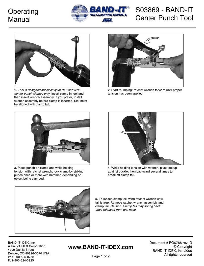
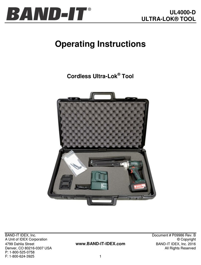
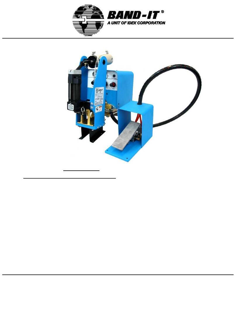
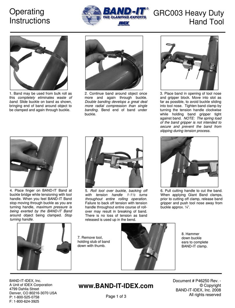
Other Band-it Tools manuals

Band-it
Band-it GRS038 User manual

Band-it
Band-it UL4000-D User manual

Band-it
Band-it GRC002 User manual

Band-it
Band-it C002 JR User manual

Band-it
Band-it G40269 Giant II User manual

Band-it
Band-it A92079 User manual

Band-it
Band-it GRC001 User manual

Band-it
Band-it IT1000-C User manual

Band-it
Band-it C00269 User manual

Band-it
Band-it GRC003 User manual
Popular Tools manuals by other brands

Peachtree
Peachtree 3262 instructions

Central Forge
Central Forge 92553 Owner's manual & safety instructions

Hilti
Hilti HIT-CT 1 Instructions for use

Fein
Fein VersaMAG VISE Series instruction manual

Milwaukee
Milwaukee M18 ONEFHIWF1D Original instructions

Universal Tool
Universal Tool UT8674-1 General Safety Information & Replacement Parts