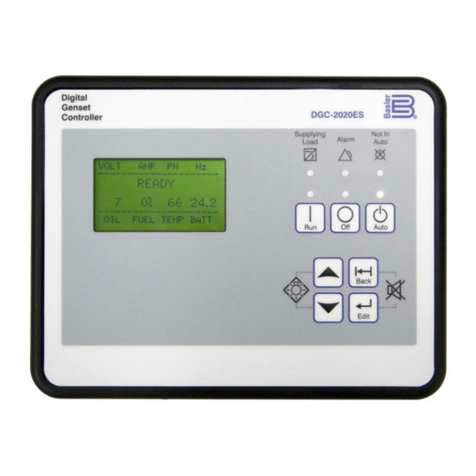
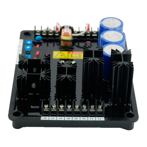
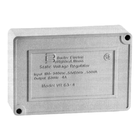
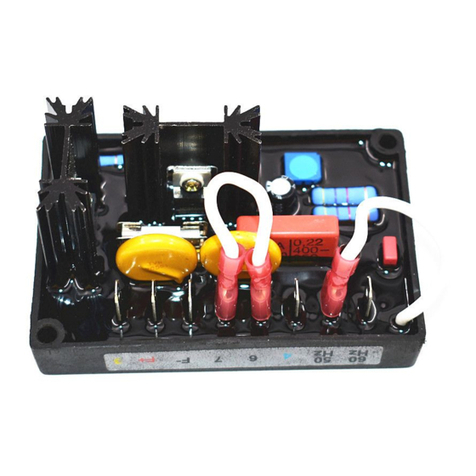
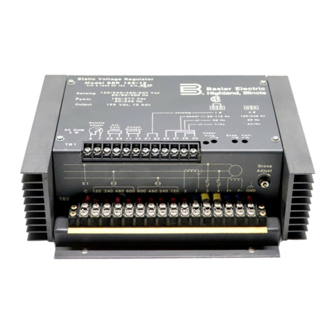
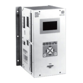
Basler SCP 250 User manual

INSTRUCTION MANUAL
FOR
VAR/POWER FACTOR CONTROLLER
SCP 250
Publication: 9 1100 00 99Y
Revision: T 01/08


911000099Y Rev T SCP 250 Introduction i
INTRODUCTION
This instruction manual provides information about the operation and installation of the SCP 250
Var/Power Factor Controller. To accomplish this, the following information is provided.
•General Information and Specifications
•Control Descriptions
•Functional Description
•Installation Drawings
•Operating Procedures
WARNING!
To avoid personal injury or equipment damage, only qualified personnel should
perform the procedures in this manual.
CAUTION
The use of high potential test equipment will damage SCP 250 circuitry.

First Printing: November 1984
Printed in USA
Copyright © 2008 Basler Electric, Highland Illinois, USA
January 2008
CONFIDENTIAL INFORMATION
of Basler Electric, Highland Illinois, USA. It is loaned for confidential use, subject
to return on request, and with the mutual understanding that it will not be used in
any manner detrimental to the interest of Basler Electric.
It is not the intention of this manual to cover all details and variations in equipment, nor does this manual
provide data for every possible contingency regarding installation or operation. The availability and design
of all features and options are subject to modification without notice. Should further information be
required, contact Basler Electric.
BASLER ELECTRIC
ROUTE 143, BOX 269
HIGHLAND IL 62249 USA
PHONE +1 618.654.2341 FAX +1 618.654.2351
ii SCP 250 Introduction 911000099Y Rev T

911000099Y Rev T SCP 250 Introduction iii
CONTENTS
SECTION 1 •GENERAL INFORMATION ................................................................................................ 1-1
INTRODUCTION................................................................................................................................. 1-1
FEATURES ......................................................................................................................................... 1-1
APPLICATION .................................................................................................................................... 1-1
Generator Peaking Application (SCP 250-G)............................................................................... 1-1
Synchronous Motor Application (SCP 250-M).............................................................................. 1-1
Isolated Bus Applications ............................................................................................................. 1-2
PART NUMBERS................................................................................................................................ 1-2
SPECIFICATIONS .............................................................................................................................. 1-2
Voltage Sensing and Input Power ................................................................................................ 1-2
Current Sensing............................................................................................................................ 1-2
Output Signal................................................................................................................................ 1-2
Enable Contact ............................................................................................................................. 1-2
Control Accuracy .......................................................................................................................... 1-2
Type Tests .................................................................................................................................... 1-3
UL Recognition ............................................................................................................................. 1-3
GOST-R Certification.................................................................................................................... 1-3
Operating Temperature ................................................................................................................ 1-3
Weight........................................................................................................................................... 1-3
SECTION 2 •CONTROLS ........................................................................................................................ 2-1
CONTROLS ILLUSTRATION AND DESCRIPTION........................................................................... 2-1
SECTION 3 •FUNCTIONAL DESCRIPTION ........................................................................................... 3-1
INTRODUCTION................................................................................................................................. 3-1
INPUTS ............................................................................................................................................... 3-1
COMPARATOR AND ERROR AMPLIFIER........................................................................................ 3-1
VOLTAGE LIMITING........................................................................................................................... 3-2
CONTROL RELAY.............................................................................................................................. 3-2
SECTION 4 •INSTALLATION .................................................................................................................. 4-1
GENERAL ........................................................................................................................................... 4-1
MOUNTING......................................................................................................................................... 4-1
CONNECTIONS.................................................................................................................................. 4-3
Interconnection Diagrams............................................................................................................. 4-3
Remote Control of the SCP 250 .................................................................................................4-19
SECTION 5 •OPERATION....................................................................................................................... 5-1
INTRODUCTION................................................................................................................................. 5-1
GENERATOR APPLICATIONS .......................................................................................................... 5-1
Preliminary Adjustments for Var Control ...................................................................................... 5-1
Preliminary Adjustments for Power Factor Control ...................................................................... 5-2
MOTOR APPLICATIONS.................................................................................................................... 5-3
Preliminary Adjustments for Power Factor Control ...................................................................... 5-3
Figures
Figure 2-1. SCP 250 Controls ................................................................................................................... 2-1
Figure 3-1. SCP 250 Function Block Diagram .......................................................................................... 3-1
Figure 4-1. SCP 250 Outline and Drilling Dimensions .............................................................................. 4-2
Figure 4-2. AVC63-12/AVC-125-10 and SCP 250-G Connections ........................................................... 4-4
Figure 4-3. KR-F/KR-FF and SCP 250-G Connections............................................................................. 4-5
Figure 4-4. KR-F/KR-FF and SCP 250-M Connections ............................................................................ 4-6
Figure 4-5. MVC 236, RA-70, AND SCP 250-M Connections .................................................................. 4-7
Figure 4-6. SR-A and SCP 250-G Connections ........................................................................................ 4-8
Figure 4-7. SR-A and SCP 250-M Connections........................................................................................ 4-9
Figure 4-8. SR-E/SR-F/SR-H and SCP 250-G Connections................................................................... 4-10
Figure 4-9. SR-E/SR-F/SR-H and SCP 250-M Connections .................................................................. 4-11
Figure 4-10. SSE and SCP 250-G Connections ..................................................................................... 4-12
iv SCP 250 Introduction 911000099Y Rev T
Figure 4-11. SSE and SCP 250-M Connections ..................................................................................... 4-13
Figure 4-12. SSR and SCP 250-G Connections ..................................................................................... 4-14
Figure 4-13. XR2001/XR2001F and SCP 250-G Connections ............................................................... 4-15
Figure 4-14. XR2001/XR2001F, SPM 2000, and SCP 250-G Connections ........................................... 4-16
Figure 4-15. XR2002/XR2002F and SCP 250-G Connections ............................................................... 4-17
Figure 4-16. XR2003/XR2003F and SCP 250-G Connections ............................................................... 4-18
Figure 4-17. Potentiometer and Switch Connections .............................................................................. 4-19
Figure 5-1. Power Factor Relationships .................................................................................................... 5-1
Tables
Table 1-1. SCP 250 Part Numbers............................................................................................................ 1-2
Table 2-1. Description of SCP 250 Controls ............................................................................................. 2-1
Table 4-1. SCP 250 Interconnection Diagrams......................................................................................... 4-3

911000099Y Rev T SCP 250 General Information 1-1
SECTION 1 •GENERAL INFORMATION
INTRODUCTION
The SCP 250 controls generator (SCP 250-G) or motor (SCP 250-M) power factor or vars by monitoring
the voltage and current and supplying a control input to a voltage regulator.
When the SCP 250 is controlling vars, the voltage regulator (or static exciter) output changes to attain the
selected reactive load current.
When the SCP 250 is controlling power factor, the voltage regulator adjusts the excitation until the
selected power factor is obtained.
The SCP 250 monitors the open/closed state of the circuit breaker so that the voltage regulator controls
excitation when the breaker is open and the SCP 250 controls excitation when the breaker is closed.
A voltage limiting feature in the SCP 250 prevents the voltage regulator from supplying full or no
excitation if utility power is lost and the peaking generator main breaker remains closed. Voltage limiting is
adjustable between ±10% and ±30%.
Because the SCP 250 is designed for behind-the-panel mounting, provisions are included for locating the
Var/PF switch and potentiometer remotely.
FEATURES
SCP 250 Var/Power Factor Controllers have the following features.
•Suitable for use in generator or synchronous motor applications
•Provide system control over a wide range of loading conditions
•Accommodate standard voltage sensing inputs
•Front panel selection of either var or power factor control
•Do not require use of motor operated control
•Specifically designed to operate with the standard Basler SR , KR, selected AVCs, SSR regulator
series, and SSE static exciter-regulators
•During power factor control, reactive load changes automatically when kW load is changed
•Easily calibrated on site
•UL recognized and CSA certified
APPLICATION
The SCP 250 is suitable for use in generator peaking and synchronous motor applications.
Generator Peaking Application (SCP 250-G)
In peaking generator applications, the paralleling circuit of a voltage regulator presents large changes in
reactive current when the bus voltage changes by a relatively small amount. However, the regulator’s
ability to compensate for large changes in bus voltage can be exceeded. Two examples illustrate typical
problem areas.
Example 1. A generator equipped with a voltage regulator adjusted for 4% droop can
have a variation in var load from zero to 100% with a 4% decrease in bus voltage.
Further decreases in bus voltage would overload the generator.
Example 2. An increase in bus voltage can cause leading power factor conditions with
the associated danger of the machine pulling out of synchronization.
To minimize the possibility of either example occurring, the SCP 250 is used and adjusted for operation in
a “safe” region with either a regulated “fixed” var level or a “fixed” power factor. Thus, for a large change
in reactive current due to bus voltage changes, the operating generator is unaffected.
Synchronous Motor Application (SCP 250-M)
In synchronous motor applications, the SCP 250 allows the desired operating power factor to be pre-
programmed so that the motor power factor remains constant during normal loading conditions. During
transient loading conditions, the SCP 250 makes corrective motor field excitation adjustments through a
regulator or exciter-regulator and thereby minimizes the possibility of synchronous pullout.

CAUTION
The SCP 250 should not be put into operation until after the motor is up to rated
speed and the field is excited.
Isolated Bus Applications
The SCP 250 is not intended for use on isolated bus systems (systems providing power independent of a
larger power source, such as a utility). In an isolated bus system using precise voltage regulators with
parallel compensation, the var load is automatically divided between the generators by the regulator and
its associated paralleling circuit.
PART NUMBERS
Table 1-1 lists the model numbers, part numbers, and application information for standard-order SCP 250
controllers.
Table 1-1. SCP 250 Part Numbers
Model Number Part Number Application
SCP 250-G-60 9 1100 00 109 60 Hz generators
SCP 250-G-50 9 1100 00 110 50 Hz generators
SCP 250-M-60 9 1100 00 111 60 Hz motors
SCP 250-M-50 9 1100 00 112 50 Hz motors
SPECIFICATIONS
SCP 250 electrical and physical specifications are listed in the following paragraphs.
Voltage Sensing and Input Power
60 Hz Voltage Range: 120 to 139 Vac, 208 to 240 Vac, 416 to 480 Vac, 520 to 600 Vac, ±10%
50 Hz Voltage Range: 100 to 120 Vac, 190 to 208 Vac, 380 to 415 Vac, 440 to 500 Vac, ±10%
Configuration: Single-phase
Common Terminal: E1
Current Sensing
Nominal Rating: 3 to 5 Aac
15 Second Rating: 30 Aac
Configuration: Single-phase
Burden: 3 VA
Terminals: 1, 2
Output Signal
Low Range: ±1 to ±3 Vdc (jumper installed at terminals X and Y)
High Range: ±1 to ±9 Vdc (jumper removed)
Terminals: A, B, C
Enable Contact
Rating: 60 Vac, 39 mA
Terminals: J, K
Control Accuracy
Power Factor: Reactive component of current is proportional to real component within
±5% of maximum rated current.
Vars: Reactive component of current maintained at programmed level within
±5% of maximum rated current.
1-2 SCP 250 General Information 911000099Y Rev T

911000099Y Rev T SCP 250 General Information 1-3
Type Tests
Vibration: 2 G in each of three mutually perpendicular planes swept over the range
of 10 to 500 Hz for a total of six sweeps, 15 minutes per sweep
Shock: Withstands up to 15 G in each of three mutually perpendicular planes
UL Recognition
Recognized per standard 508, UL file E75380
GOST R Certification
Gost R certified No. POCC US.ME05.B03392; is in compliance with relevant standards of Gosstandart of
Russia. Issued by accredited certification body POCC RU.0001.11ME05.
Operating Temperature
Range: –40 to 70°C (–40 to 158°F)
Weight
Net: 6.75 lb (3.06 kg)
Shipping: 8.0 lb (3.63 kg)

This page intentionally left blank.
1-4 SCP 250 General Information 911000099Y Rev T

SECTION 2 •CONTROLS
CONTROLS ILLUSTRATION AND DESCRIPTION
SCP 250 controls are shown in Figure 2-1 and described in Table 2-1.
Figure 2-1. SCP 250 Controls
Table 2-1. Description of SCP 250 Controls
Locator Control Description
A Mode Switch. This switch selects between var and power factor control.
When the mode switch is in the VAR position, the desired reactive power level is
established with the Var/Power Factor Adjust control. The var level is then held constant
and will not vary if changes in watt load occur.
When the mode switch is in the Power Factor position, the desired power factor is
established using the Var/Power Factor Adjust control. The power factor is held constant
even if watt load varies.
911000099Y Rev T SCP 250 Controls 2-1

2-2 SCP 250 Controls 911000099Y Rev T
Locator Control Description
B Var/Power Factor Adjust Control. This control is used to establish the var level or power
factor, depending on the position of the mode switch. The control has two sets of calibration
marks—one set for var control and one set for power factor control. The power factor
calibration marks shown in Figure 2-1 are for an SCP 250-M and will differ from the power
factor calibration marks on an SCP 250-G.
C VAR Range Control. This single-turn potentiometer calibrates the SCP 250 when the mode
switch is the VAR position. Var calibration is described in Section 5, Operation.
D Output Limit Control. This single-turn potentiometer adjusts the control output of the SCP
250. The output is adjustable from approximately ±1 Vdc (fully counterclockwise) to
approximately ±3 Vdc (fully clockwise) or ±9 Vdc (jumper removed from terminals X and Y).
This causes a corresponding change in generator output voltage of about ±10% to ±30%
when the generator is isolated from the bus.
E Balance Control. This single-turn potentiometer is ordinarily set at its midrange position. It
can be adjusted to attain extra precision in the maintenance of power factor in peaking
service over a wide range of kW loading. Use of the balance control is described in Section
5, Operation.

SECTION 3 •FUNCTIONAL DESCRIPTION
INTRODUCTION
SCP 250 functions are illustrated in Figure 3-1 and described in the following paragraphs.
Figure 3-1. SCP 250 Function Block Diagram
INPUTS
The SCP 250 has two inputs: a voltage input and a current input. The SCP 250 measures the real and
reactive power based on these two inputs. The voltage input also supplies operating power to the SCP
250 power supply.
COMPARATOR AND ERROR AMPLIFIER
When var control is selected, the reactive component is compared to an adjustable dc reference and the
error signal from this comparison is amplified and supplied to the voltage regulator. As a result, the
voltage regulator (or static exciter regulator) changes its output until the programmed reactive load current
is attained.
When power factor control is selected, the reactive component is compared with an adjustable sample of
the real power component, which serves as a reference. The error signal from this comparison is
amplified and supplied to the voltage regulator. The regulator responds by changing the excitation until
the selected power factor is attained.
911000099Y Rev T SCP 250 Functional Description 3-1

3-2 SCP 250 Functional Description 911000099Y Rev T
VOLTAGE LIMITING
The SCP 250 voltage limiter prevents the voltage regulator from supplying full or no excitation if utility
power is lost and the generator main breaker remains closed. Voltage limiting is adjustable between
±10% and ±30%.
CONTROL RELAY
The control relay (K1) enables and disables the SCP 250 output and is controlled by the Enable Contact
input (terminals J and K). The Enable Contact input is typically interconnected with external breaker
auxiliary contacts (52b).
When the external breaker is open (52b contacts closed), K1 energizes and its contacts short-circuit the
SCP 250 output terminals together. This disables the SCP 250 output and gives the voltage regulator
total control of generator excitation.
When the external breaker is closed (52b contacts open), K1 de-energizes and enables the SCP 250
output. The SCP 250 control output is applied to the voltage regulator and the SCP 250 assumes a major
portion of excitation control.

911000099Y Rev T SCP 250 Installation 4-1
SECTION 4 •INSTALLATION
GENERAL
Upon receipt of an SCP 250, check the part number against the requisition and packing list for
agreement. Inspect for damage, and if there is evidence of such, file a claim with the carrier and notify the
Basler Electric regional sales office, your sales representative, or a sales representative at Basler Electric,
Highland, Illinois.
MOUNTING
The SCP 250 is intended for back-of-the-panel mounting in any plane. It should not be installed in a
location where ambient operating temperature exceeds the range of –40 to 70°C (–40 to 158°F).
SCP 250 dimensions are shown in Figure 4-1. All terminal screws are 6-32 on 0.375 inch (9.5 millimeter)
centers. Drawing dimensions are shown in inches with millimeters in parenthesis.

Figure 4-1. SCP 250 Outline and Drilling Dimensions
4-2 SCP 250 Installation 911000099Y Rev T

CONNECTIONS
SCP 250 connections will vary according to the application (generator or motor) and the type of voltage
regulator used.
The secondary voltage of the potential transformer used in an application determines which SCP 250
power connections are used. Input power (operating power and sensing voltage) is applied to terminal E1
and one of the following terminals: 120-139 Vac, 208-240 Vac, 416-480 Vac, or 520-600 Vac.
CAUTION
The use of high potential test equipment will damage SCP 250 circuitry.
Interconnection Diagrams
The SCP 250 should be connected using the appropriate interconnection diagram. Table 4-1 lists the
interconnection diagrams for common applications using the SCP 250 and other Basler control devices.
Table 4-1. SCP 250 Interconnection Diagrams
Application Diagram
AVC63-12/AVC125-10 voltage regulator and SCP 250-G Figure 4-2
KR-F/KR-FF voltage regulator and SCP 250-G Figure 4-3
KR-F/KR-FF voltage regulator and SCP 250-M Figure 4-4
MVC 236 manual voltage control, RA-70P reference adjuster, and SCP 250-M Figure 4-5
SR-A voltage regulator and SCP 250-G Figure 4-6
SR-A voltage regulator and SCP 250-M Figure 4-7
SR-E/SR-F/SR-H voltage regulator and SCP 250-G Figure 4-8
SR-E/SR-F/SR-H voltage regulator and SCP 250-M Figure 4-9
SSE control chassis and SCP 250-G Figure 4-10
SSE control chassis and SCP 250-M Figure 4-11
SSR voltage regulator and SCP 250-G Figure 4-12
XR2001/XR2001F voltage regulator and SCP 250-G Figure 4-13
XR2001/XR2001F voltage regulator, SCP 250-G, and three-phase sensing module Figure 4-14
XR2002/XR2002F voltage regulator and SCP 250-G Figure 4-15
XR2003/XR2003F voltage regulator and SCP 250-G Figure 4-16
911000099Y Rev T SCP 250 Installation 4-3

Figure 4-2. AVC63-12/AVC125-10 and SCP 250-G Connections
4-4 SCP 250 Installation 911000099Y Rev T

911000099Y Rev T SCP 250 Installation 4-5
Figure 4-3. KR-F/KR-FF and SCP 250-G Connections

4-6 SCP 250 Installation 911000099Y Rev T
Figure 4-4. KR-F/KR-FF and SCP 250-M Connections
This manual suits for next models
6
Table of contents
Other Basler Controllers manuals

Basler
Basler AVC63-4A User manual

Basler
Basler AEC 42-7 User manual

Basler
Basler AVC63-12 User manual

Basler
Basler DECS-200 User manual

Basler
Basler AVC634A-12 User manual

Basler
Basler DGC-2020ES Quick guide

Basler
Basler BE2000E User manual

Basler
Basler DGC-2020ES User manual

Basler
Basler AVC63-2.5 User manual

Basler
Basler KR4FFX User manual

Basler
Basler DGC-2020HD Service manual

Basler
Basler DGC-500 User manual

Basler
Basler DGC-2020 User manual

Basler
Basler APR 63-5 User manual

Basler
Basler SR4A User manual

Basler
Basler AVC63-4 User manual

Basler
Basler DGC-2020ES User manual

Basler
Basler AVC63-4A User manual

Basler
Basler DECS-250 User manual

Basler
Basler SR6A User manual