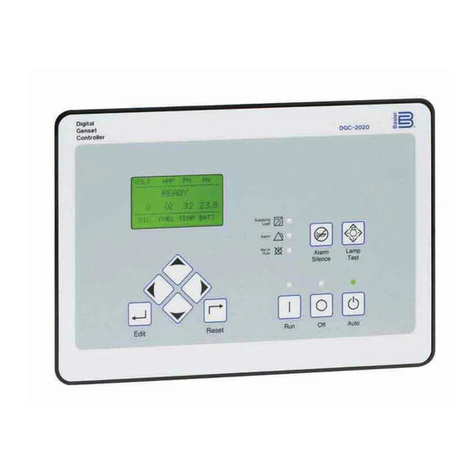
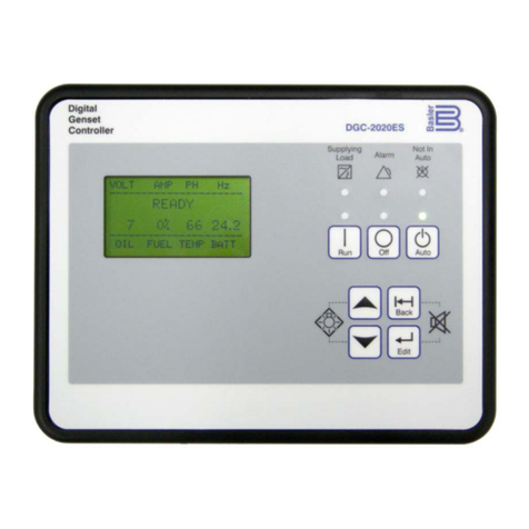
Basler DGC-2020ES User manual

INSTRUCTION MANUAL
FOR
DGC-2020ES
DIGITAL GENSET CONTROLLER
Installation
Publication: 9469200994
Revision: — Apr-17


9469200994 Rev — i
DGC-2020ES Preface
Preface
This instruction manual provides information about the installation of the DGC-2020ES Digital Genset
Controller. To accomplish this, the following information is provided:
•Mounting
•Terminals and connectors
•Typical applications
•Power input
•Voltage and current sensing
•Speed signal inputs
•Specifications
•Maintenance and troubleshooting
Conventions Used in this Manual
Important safety and procedural information is emphasized and presented in this manual through
Warning, Caution, and Note boxes. Each type is illustrated and defined as follows.
Warning!
Warning boxes call attention to conditions or actions that may cause
personal injury or death.
Caution
Caution boxes call attention to operating conditions that may lead to
equipment or property damage.
Note
Note boxes emphasize important information pertaining to Digital
Genset Controller installation or operation.
DGC-2020ES Instruction Manual Catalog
Available instruction manuals for the DGC-2020ES are listed in Table 1.
Table 1. Instruction Manuals
Part Number
Description
9469200993
Quick Start
9469200994
Installation (this manual)
9469200995
Configuration
9469200996
Operation
9469200997
Accessories

ii 9469200994 Rev —
Preface DGC-2020ES
12570 State Route 143
Highland IL 62249-1074 USA
www.basler.com
info@basler.com
Tel: +1 618.654.2341
Fax: +1 618.654.2351
© 2017 by Basler Electric
All rights reserved
First printing: April 2017
Warning!
READ THIS MANUAL. Read this manual before installing, operating, or maintaining the DGC-2020ES.
Note all warnings, cautions, and notes in this manual as well as on the product. Keep this manual with
the product for reference. Only qualified personnel should install, operate, or service this system.
Failure to follow warning and cautionary labels may result in personal injury or property damage.
Exercise caution at all times.
Basler Electric does not assume any responsibility to compliance or noncompliance with national code, local code,
or any other applicable code. This manual serves as reference material that must be well understood prior to
installation, operation, or maintenance.
For terms of service relating to this product and software, see the Commercial Terms of Products and Services
document available at www.basler.com/terms.
This publication contains confidential information of Basler Electric Company, an Illinois corporation. It is loaned for
confidential use, subject to return on request, and with the mutual understanding that it will not be used in any
manner detrimental to the interests of Basler Electric Company and used strictly for the purpose intended.
It is not the intention of this manual to cover all details and variations in equipment, nor does this manual provide
data for every possible contingency regarding installation or operation. The availability and design of all features
and options are subject to modification without notice. Over time, improvements and revisions may be made to this
publication. Before performing any of the following procedures, contact Basler Electric for the latest revision of this
manual.
The English-language version of this manual serves as the only approved manual version.

9469200994 Rev — iii
DGC-2020ES Preface
This product contains, in part, open source software (software licensed in a way that ensures freedom to run,
copy, distribute, study, change, and improve the software) and you are granted a license to that software under the
terms of either the GNU General Public License or GNU Lesser General Public License. The licenses, at the time
of sale of the product, allow you to freely copy, modify, and redistribute that software and no other statement or
documentation from us, including our End User License Agreement, places any additional restrictions on what you
may do with that software.
For at least three (3) years from the date of distribution of this product, a machine-readable copy of the complete
corresponding source code for the version of the programs distributed to you will be sent upon request (contact
information is provided above). A fee of no more than our cost of physically performing the source code distribution
is charged.
The source code is distributed in the hope that it will be useful, but WITHOUT ANY REPRESENTATION or
WARRANTY or even the implied warranty of MERCHANTABILITY or FITNESS FOR A PARTICULAR PURPOSE.
Refer to the source code distribution for additional restrictions regarding warranty and copyrights.
For a complete copy of GNU GENERAL PUBLIC LICENSE Version 2, June 1991 or GNU LESSER GENERAL
PUBLIC LICENSE Version 2.1, February 1999 refer to www.gnu.org or contact Basler Electric. You, as a Basler
Electric Company customer, agree to abide by the terms and conditions of GNU GENERAL PUBLIC LICENSE
Version 2, June 1991 or GNU LESSER GENERAL PUBLIC LICENSE Version 2.1, February 1999, and as such
hold Basler Electric Company harmless related to any open source software incorporated in this product. Basler
Electric Company disclaims any and all liability associated with the open source software and the user agrees to
defend and indemnify Basler Electric Company, its directors, officers, and employees from and against any and all
losses, claims, attorneys' fees, and expenses arising from the use, sharing, or redistribution of the software.
Review the software website for the latest version of the software documentation.
Portions of this software are copyright © 2014 The FreeType Project (www.freetype.org). All rights reserved.
The following statement applies only to the fontconfig library:
fontconfig/COPYING
Copyright © 2000,2001,2002,2003,2004,2006,2007 Keith Packard
Copyright © 2005 Patrick Lam
Copyright © 2009 Roozbeh Pournader
Copyright © 2008,2009 Red Hat, Inc.
Copyright © 2008 Danilo Šegan
Copyright © 2012 Google, Inc.
Permission to use, copy, modify, distribute, and sell this software and its documentation for any purpose is hereby
granted without fee, provided that the above copyright notice appear in all copies and that both that copyright
notice and this permission notice appear in supporting documentation, and that the name of the author(s) not be
used in advertising or publicity pertaining to distribution of the software without specific, written prior permission.
The authors make no representations about the suitability of this software for any purpose. It is provided "as is"
without express or implied warranty.
THE AUTHOR(S) DISCLAIMS ALL WARRANTIES WITH REGARD TO THIS SOFTWARE, INCLUDING ALL
IMPLIED WARRANTIES OF MERCHANTABILITY AND FITNESS, IN NO EVENT SHALL THE AUTHOR(S) BE
LIABLE FOR ANY SPECIAL, INDIRECT OR CONSEQUENTIAL DAMAGES OR ANY DAMAGES WHATSOEVER
RESULTING FROM LOSS OF USE, DATA OR PROFITS, WHETHER IN AN ACTION OF CONTRACT,
NEGLIGENCE OR OTHER TORTIOUS ACTION, ARISING OUT OF OR IN CONNECTION WITH THE USE OR
PERFORMANCE OF THIS SOFTWARE.

iv 9469200994 Rev —
Preface DGC-2020ES

9469200994 Rev — v
DGC-2020ES Contents
Contents
Mounting......................................................................................................................................................1
Hardware...................................................................................................................................................1
Dimensions................................................................................................................................................1
Terminals and Connectors.........................................................................................................................3
Connections............................................................................................................................................... 4
Operating Power........................................................................................................................................4
Generator Current Sensing ....................................................................................................................... 5
Generator Voltage Sensing.......................................................................................................................5
Bus Voltage Sensing.................................................................................................................................5
Analog Engine Sender Inputs....................................................................................................................6
Magnetic Pickup Input...............................................................................................................................6
Contact Sensing Inputs .............................................................................................................................6
Output Contacts.........................................................................................................................................7
USB Interface............................................................................................................................................ 7
CAN Interface............................................................................................................................................7
Optional Remote Display Panel Connections ...........................................................................................8
Typical Connections...................................................................................................................................9
Connections for Typical Applications ........................................................................................................ 9
CAN Connections....................................................................................................................................13
CEM-2020 Connections ..........................................................................................................................14
Installation for CE Systems .....................................................................................................................14
Installation in an Ungrounded System Application..................................................................................14
Power Input................................................................................................................................................15
Nominal Voltage Input and Acceptable Range of Input Voltage.............................................................15
Terminal Assignments.............................................................................................................................15
Power Consumption................................................................................................................................15
Battery Ride-Through Capability.............................................................................................................15
Fuse Protection .......................................................................................................................................15
Voltage and Current Sensing...................................................................................................................17
Generator Voltage...................................................................................................................................17
Bus Voltage .............................................................................................................................................17
Generator Current ...................................................................................................................................17
Speed Signal Inputs..................................................................................................................................19
Magnetic Pickup......................................................................................................................................19
Generator Sensing Voltage.....................................................................................................................19
Specifications............................................................................................................................................21
Control Power..........................................................................................................................................21
Battery Ride Through ..............................................................................................................................21
Current Sensing.......................................................................................................................................21
Voltage Sensing ......................................................................................................................................21
Contact Sensing......................................................................................................................................22
Engine System Inputs..............................................................................................................................22
Output Contacts.......................................................................................................................................23
Metering...................................................................................................................................................23
Generator Protection Functions ..............................................................................................................26
Logic Timers............................................................................................................................................26
Communication Interface.........................................................................................................................26
Real-Time Clock......................................................................................................................................27
Liquid Crystal Display (LCD) ...................................................................................................................27
Type Tests...............................................................................................................................................27
Environment ............................................................................................................................................28
UL Approval.............................................................................................................................................28

vi 9469200994 Rev —
Contents DGC-2020ES
CSA Certification.....................................................................................................................................28
CE Compliance........................................................................................................................................29
NFPA Compliance...................................................................................................................................29
EAC Mark (Eurasian Conformity)............................................................................................................29
Physical ...................................................................................................................................................29
Maintenance ..............................................................................................................................................31
Storage....................................................................................................................................................31
Troubleshooting........................................................................................................................................33
Communications......................................................................................................................................33
Inputs and Outputs..................................................................................................................................33
Metering/Display......................................................................................................................................33
Ground Faults Detected in Ungrounded System Applications................................................................34
Generator Breaker and Mains Breaker ...................................................................................................35
DGC-2020ES Front Panel Debug Screen...............................................................................................37
Revision History........................................................................................................................................39

9469200994 Rev — 1
DGC-2020ES Mounting
Mounting
DGC-2020ES controllers are delivered in sturdy cartons to prevent shipping damage. Upon receipt of a
unit, check the part number against the requisition and packing list for agreement. Inspect for damage,
and if there is evidence of such, immediately file a claim with the carrier and notify the Basler Electric
regional sales office or your sales representative.
If the device is not installed immediately, store it in the original shipping package in a moisture- and dust-
free environment.
Hardware
The front panel is resistant to moisture, salt fog, humidity, dust, dirt, and chemical contaminants. DGC-
2020ES controllers are mounted using the four permanently attached 10-24 studs. The torque applied to
the mounting hardware should not exceed 20 inch-pounds (2.2 newton meters).
Dimensions
Panel cutting and drilling dimensions are shown in Figure 1. Overall dimensions are shown in Figure 2. All
dimensions are shown in inches with millimeters in parenthesis.
Figure 1. Panel Cutting and Drilling Dimensions
P0067-98
7.433 (188.8) max
7.393 (187.8) min
7.635 (194.0) max
7.615 (193.4) min
5.635 (143.2) max
5.615 (142.6) min
5.433 (138) max
5.393 (137) min
0.218 (5.5) diameter
CUTOUT
0.242 (6.2) max
0.182 (4.6) min
0.242 (6.2) max
0.182 (4.6) min
0.320 (8.1) max
0.280 (7.1) min
45°

2 9469200994 Rev —
Mounting DGC-2020ES
Figure 2. Overall Dimensions

9469200994 Rev — 3
DGC-2020ES Terminals and Connectors
Terminals and Connectors
All DGC-2020ES terminals and connectors are located on the rear panel. DGC-2020ES terminals consist
of a mini-B USB socket and plug-in connectors with spring clamp terminals.
Figure 3 illustrates the rear panel terminals. Locator letters in the illustration correspond to the terminal
block and connector descriptions in Table 1.
Figure 3. Rear Panel

4 9469200994 Rev —
Terminals and Connectors DGC-2020ES
Table 1. Rear Panel Terminal and Connector Descriptions
Locator
Description
A
The majority of external, DGC-2020ES wiring is terminated at 8- or 15-position
connectors with spring clamp terminals. These connectors plug into headers on the
DGC-2020ES. The connectors and headers have a dovetailed edge that ensures
proper connector orientation. Each connector and header is uniquely keyed to ensure
that a connector mates only with the correct header. Spring clamp terminals accept a
maximum wire size of 12 AWG.
B
The mini-B USB socket mates with a standard USB cable and is used with a PC
running BESTCOMSPlus
®
software for local communication with the DGC-2020ES.
Connections
DGC-2020ES connections are dependent on the application. Incorrect wiring may result in damage to the
controller.
Note
Be sure that the DGC-2020ES is hard-wired to earth ground with no
smaller than 12 AWG copper wire attached to the chassis ground
terminal (terminal 16) on the rear of the controller.
Operating power from the battery must be of the correct polarity.
Although reverse polarity will not cause damage, the DGC-2020ES will
not operate.
For the DGC-2020ES to correctly meter power factor, the generator
must be rotating clockwise (A-B-C).
The DGC-2020ES terminals are grouped by function and include operating power, generator current
sensing, generator voltage sensing, bus voltage sensing, analog engine sender inputs, magnetic pickup
input, contact sensing inputs, output contacts, USB interface, CAN interface, and Remote Display Panel
connections.
DGC-2020ES terminal groups are described in the following paragraphs.
Operating Power
The DGC-2020ES operating power input accepts either 12 Vdc or 24 Vdc and tolerates voltage over the
range of 6 to 32 Vdc. Operating power must be of the correct polarity. Although reverse polarity will not
cause damage, the DGC-2020ES will not operate. Operating power terminals are listed in Table 2.
It is recommended that a fuse be added for additional protection for the wiring to the battery input of the
DGC-2020ES. A fuse helps prevent wire damage and nuisance trips due to initial power supply inrush
current. To follow UL guidelines, a 5 A maximum, 32 Vdc supplementary fuse must be implemented in the
battery input circuit to the DGC-2020ES
Table 2. Operating Power Terminals
Terminal
Description
16 (CHASSIS)
Chassis ground connection
17 (BATT–)
Negative side of operating power input
18 (BATT+)
Positive side of operating power input

9469200994 Rev — 5
DGC-2020ES Terminals and Connectors
Generator Current Sensing
The DGC-2020ES has sensing inputs for A-phase, B-phase, and C-phase generator current. A DGC-
2020ES with a style number of 1xx has a 1 Aac nominal current sensing and a DGC-2020ES with a style
number of 5xx indicates 5 Aac nominal current sensing. Generator current sensing terminals are listed in
Table 3.
Table 3. Generator Current Sensing Terminals
Terminals
Description
37 (IA–)
A-phase current sensing input
38 (IA+)
35 (IB–)
B-phase current sensing input
36 (IB+)
33 (IC–)
C-phase current sensing input
34 (IC+)
Note
Unused current sensing inputs should be shorted to minimize noise
pickup.
Caution
Generator current sensing terminals 37 (IA–), 35 (IB–), and 33 (IC–)
must be terminated to ground for proper operation.
Generator Voltage Sensing
The DGC-2020ES accepts either line-to-line or line-to-neutral generator sensing voltage over the range of
12 to 576 volts, rms line-to-line. Generator voltage sensing terminals are listed in Table 4.
Table 4. Generator Voltage Sensing Terminals
Terminal
Description
40 (GEN VN)
Neutral generator voltage sensing input
41 (GEN VC)
C-phase generator voltage sensing input
43 (GEN VB)
B-phase generator voltage sensing input
45 (GEN VA)
A-phase generator voltage sensing input
Installation in an Ungrounded System Application
When the DGC-2020ES is controlling equipment that is part of an ungrounded system, it is recommended
that potential transformers be employed on the voltage sensing inputs to provide full isolation between the
DGC-2020ES and monitored voltage phases.
Bus Voltage Sensing
Sensing of bus voltage enables the DGC-2020ES to detect failures of the mains (utility). The DGC-
2020ES senses A-phase, B-phase, and C-phase bus voltage. Bus voltage sensing terminals are listed in
Table 5.

6 9469200994 Rev —
Terminals and Connectors DGC-2020ES
Table 5. Bus Voltage Sensing Terminals
Terminal
Description
46 (BUS VA)
A-phase bus voltage sensing input
48 (BUS VB)
B-phase bus voltage sensing input
50 (BUS VC)
C-phase bus voltage sensing input
Installation in an Ungrounded System Application
When the DGC-2020ES is controlling equipment that is part of an ungrounded system, it is recommended
that potential transformers be employed on the voltage sensing inputs to provide full isolation between the
DGC-2020ES and monitored voltage phases.
Analog Engine Sender Inputs
Inputs are provided for oil pressure, fuel level, and coolant temperature senders. For a listing of oil
pressure, fuel level, and coolant temperature senders that are compatible with the DGC-2020ES, refer to
the Engine Sender Inputs chapter in the Configuration manual. Analog engine sender input terminals are
listed in Table 6.
Table 6. Sender Input Terminals
Terminal
Description
1 (FUEL)
Fuel level sender input
2 (SENDER COM)
Sender return terminal
52 (OIL)
Oil pressure sender input
53 (COOLANT)
Coolant temperature sender input
Magnetic Pickup Input
The magnetic pickup input accepts a speed signal over the range of 3 to 35 volts peak and 32 to 10,000
hertz. Magnetic pickup input terminals are listed in Table 7.
Table 7. Magnetic Pickup Input Terminals
Terminals
Description
31 (MPU–)
Magnetic pickup return input
32 (MPU+)
Magnetic pickup positive input
Contact Sensing Inputs
Contact sensing inputs consist of seven programmable inputs. The programmable inputs accept normally
open, dry contacts. Terminal 17 (BATT–) serves as the common return line for the programmable inputs.
While input 1 is programmed to recognize an emergency stop input by default, it can be programmed for
any function. Information about configuring the programmable inputs is provided in the Contact Inputs
chapter in the Configuration manual. Contact sensing input terminals are listed in Table 8.
Table 8. Contact Sensing Inputs
Terminal
Description
17 (BATT–)
Common return line for programmable contact inputs
3 (INPUT 1)
Programmable contact input 1 (ESTOP by default)
4 (INPUT 2)
Programmable contact input 2
5 (INPUT 3)
Programmable contact input 3

9469200994 Rev — 7
DGC-2020ES Terminals and Connectors
Terminal
Description
6 (INPUT 4)
Programmable contact input 4
7 (INPUT 5)
Programmable contact input 5
8 (INPUT 6)
Programmable contact input 6
9 (INPUT 7)
Programmable contact input 7
Output Contacts
The DGC-2020ES has three sets of fixed-function output contacts: Pre, Start, and Run. The Pre contacts
supply battery power to the engine glow plugs, the Start contacts supply power to the starter solenoid,
and the Run contacts supply power to the fuel solenoid. Connections to the three sets of contacts are
made at terminals 19 through 24. The Pre, Start, and Run relay terminals are listed in Table 9.
Table 9. Fixed-Function Output Contact Terminals
Terminal
Description
19 (START)
Start output contact (Start solenoid)
20 (START)
21 (RUN)
Run output contact (Fuel solenoid)
22 (RUN)
23 (PRE)
Pre-start output contact (Glow plugs)
24 (PRE)
Four programmable output contacts are provided in two sets. Each set of two output contacts share a
common terminal. Programmable output contact terminals are listed in Table 10.
Table 10. Programmable Output Contact Terminals
Terminal
Description
25 (COM 1, 2)
Common connection for outputs 1 and 2
26 (OUT 1)
Programmable output 1
27 (OUT 2)
Programmable output 2
28 (COM 3, 4)
Common connection for outputs 3 and 4
29 (OUT 3)
Programmable output 3
30 (OUT 4)
Programmable output 4
USB Interface
A mini-B USB socket enables local communication with a PC running BESTCOMSPlus software. The
DGC-2020ES is connected to a PC using a standard USB cable equipped with a type A plug on one end
(PC termination) and a mini-B plug on the other end (DGC-2020ES termination).
CAN Interface
These terminals provide communication using the SAE J1939 protocol or the MTU protocol and provide
high-speed communication between the DGC-2020ES and an ECU on an electronically controlled
engine. Connections between the ECU and DGC-2020ES should be made with twisted-pair, shielded
cable. CAN interface terminals are listed in Table 11. For typical CAN connections, refer to the Typical
Connections chapter.

8 9469200994 Rev —
Terminals and Connectors DGC-2020ES
Table 11. CAN Interface Terminals
Terminals
Description
13 (CAN H)
CAN high connection
14 (CAN L)
CAN low connection
15 (SHIELD)
CAN drain connection
Note
1. If the DGC-2020ES is providing one end of the J1939 bus, a
120 ohm, ½ watt terminating resistor should be installed across
terminals 14 (CANL) and 13 (CANH).
2. If the DGC-2020ES is not providing one end of the J1939 bus, the
stub connecting the DGC-2020ES to the bus should not exceed
914 mm (3 ft) in length.
3. The maximum bus length, not including stubs, is 40 m (131 ft).
4. The J1939 drain (shield) should be grounded at one point only. If
grounded elsewhere, do not connect the drain to the DGC-
2020ES
Optional Remote Display Panel Connections
Terminals are provided for connection with the optional Remote Display Panel. These terminals provide
dc operating power to the Remote Display Panel and enable communication between the DGC-2020ES
and Remote Display Panel. Twisted-pair conductors are recommended for connecting the communication
terminals of the DGC-2020ES and Remote Display Panel. Communication may become unreliable if the
connection wires exceed 1,219 m (4,000 ft). Table 12 lists the DGC-2020ES terminals that connect to the
Remote Display Panel.
Table 12. Remote Display Panel Interface Terminals
Terminal
Description
10 (RDP TxD–)
Remote Display Panel terminal (TxD–)
11 (RDP TxD+)
Remote Display Panel terminal (TxD+)
17 (BATT–)
Remote Display Panel terminal DC COM (–)
18 (BATT+)
Remote Display Panel terminal 12/24 (+)

9469200994 Rev — 9
DGC-2020ES Typical Connections
Typical Connections
Typical connection diagrams are provided in this chapter as a guide when wiring the DGC-2020ES for
communication, mechanical senders, contact inputs and outputs, sensing, and control power.
Connections for Typical Applications
Typical connections for applications using three-phase wye, three-phase delta, single-phase AB, and
single-phase AC generator voltage sensing are shown on the following pages.
Figure 4 illustrates typical three-phase wye generator voltage sensing connections.
Figure 4. Three-Phase Wye Connections for Typical Applications
GENERATOR
≤480V
32
31
MPU+
MPU–
38
IA–
37
IA+
36
IB–
35
IB+
34
IC–
33
IC+
45
GEN VA
43
GEN VB
41
GEN VC
40
GEN VN
48
BUS VB
50
BUS VC
A
B
C
N
25
26
OUT 1
27
28
29
30
OUT 2
OUT 3
OUT 4
23
24
21
22
19
20
PRE
RUN
START START
SOLENOID
FUEL
SOLENOID
17
BATT–
18
BATT+
16
CHASSIS
GLOW PLUGS
52
53
OIL
COOLANT
1
2
FUEL
SENDER COM
9
8
7
6
5
4
3
INPUT 7
INPUT 6
INPUT 5
INPUT 3
INPUT 4
INPUT 2
INPUT 1
P0071-48
M
P
U
GEN CKT
BKR
L1
L2
L3
N
Analog
Senders
12/24V
Mini-B
USB
11
RDP TxD +
12
485 SHIELD
10
RDP TxD –
14
CAN L
15
SHIELD
13
CAN H
11 1
2
DGC-2020ES
1
Labels indicate the functions assigned by the default programmable
logic to the contact inputs.
2
Current inputs are 1A or 5A, depending on style.
4Connect near engine block (negative battery terminal) side of senders.
MAINS CKT
BKR
L
O
A
D
46
BUS VA
Emergency Stop
4
7
Bus sensing inputs are optional, depending on style.
7
To ECU
CAN bus
To ECU
Power or
Key-on
Terminal
6
5If component is under ECU control, do not connect to DGC-2020ES.
Connect to the ECU on an electronically controlled engine when the
DGC-2020ES has the J1939 CAN interface option (style xCx).
6
6
5
5
5
Oil pressure and coolant temperature senders are only available when
the DGC-2020ES has the Analog Senders option (style xAx). The fuel
sender is always available.
3
3

10 9469200994 Rev —
Typical Connections DGC-2020ES
Figure 5 illustrates typical three-phase delta generator voltage sensing connections.
Figure 5. Three-Phase Delta Connections for Typical Applications
GENERATOR
≤480V
32
31
MPU+
MPU–
38
IA–
37
IA+
36
IB–
35
IB+
34
IC–
33
IC+
45
GEN VA
43
GEN VB
41
GEN VC
40
GEN VN
48
BUS VB
50
BUS VC
A
B
C
N
25
26
OUT 1
27
28
29
30
OUT 2
OUT 3
OUT 4
23
24
21
22
19
20
PRE
RUN
START START
SOLENOID
FUEL
SOLENOID
17
BATT–
18
BATT+
16
CHASSIS
GLOW PLUGS
52
53
OIL
COOLANT
1
2
FUEL
SENDER COM
9
8
7
6
5
4
3
INPUT 7
INPUT 6
INPUT 5
INPUT 3
INPUT 4
INPUT 2
INPUT 1
P0071-49
M
P
U
GEN CKT
BKR
L1
L2
L3
N
Analog
Senders
12/24V
Mini-B
USB
11
RDP TxD +
12
485 SHIELD
10
RDP TxD –
14
CAN L
15
SHIELD
13
CAN H
11 1
2
DGC-2020ES
1
Labels indicate the functions assigned by the default programmable
logic to the contact inputs.
2
Current inputs are 1A or 5A, depending on style.
4Connect near engine block (negative battery terminal) side of senders.
MAINS CKT
BKR
L
O
A
D
46
BUS VA
Emergency Stop
4
7
Bus sensing inputs are optional, depending on style.
7
To ECU
CAN bus
To ECU
Power or
Key-on
Terminal
6
5If component is under ECU control, do not connect to DGC-2020ES.
Connect to the ECU on an electronically controlled engine when the
DGC-2020ES has the J1939 CAN interface option (style xCx).
6
6
5
5
5
Oil pressure and coolant temperature senders are only available when
the DGC-2020ES has the Analog Senders option (style xAx). The fuel
sender is always available.
3
3

9469200994 Rev — 11
DGC-2020ES Typical Connections
Figure 6 illustrates typical single-phase A-B generator voltage sensing connections.
Figure 6. Single-Phase A-B Connections for Typical Applications
GENERATOR
≤480V
32
31
MPU+
MPU–
38
IA–
37
IA+
36
IB–
35
IB+
34
IC–
33
IC+
45
GEN VA
43
GEN VB
41
GEN VC
40
GEN VN
48
BUS VB
50
BUS VC
A
B
N
25
26
OUT 1
27
28
29
30
OUT 2
OUT 3
OUT 4
23
24
21
22
19
20
PRE
RUN
START START
SOLENOID
FUEL
SOLENOID
17
BATT–
18
BATT+
16
CHASSIS
GLOW PLUGS
52
53
OIL
COOLANT
1
2
FUEL
SENDER COM
9
8
7
6
5
4
3
INPUT 7
INPUT 6
INPUT 5
INPUT 3
INPUT 4
INPUT 2
INPUT 1
P0071-50
M
P
U
GEN CKT
BKR
L1
L2
N
Analog
Senders
12/24V
Mini-B
USB
11
RDP TxD +
12
485 SHIELD
10
RDP TxD –
14
CAN L
15
SHIELD
13
CAN H
11
2
DGC-2020ES
1
Labels indicate the functions assigned by the default programmable
logic to the contact inputs.
2
Current inputs are 1A or 5A, depending on style.
4Connect near engine block (negative battery terminal) side of senders.
MAINS CKT
BKR
L
O
A
D
46
BUS VA
Emergency Stop
4
7
Bus sensing inputs are optional, depending on style.
7
To ECU
CAN bus
To ECU
Power or
Key-on
Terminal
6
5If component is under ECU control, do not connect to DGC-2020ES.
Connect to the ECU on an electronically controlled engine when the
DGC-2020ES has the J1939 CAN interface option (style xCx).
6
6
5
5
5
Oil pressure and coolant temperature senders are only available when
the DGC-2020ES has the Analog Senders option (style xAx). The fuel
sender is always available.
3
3

12 9469200994 Rev —
Typical Connections DGC-2020ES
Figure 7 illustrates typical single-phase A-C generator voltage sensing connections.
Figure 7. Single-Phase A-C Connections for Typical Applications
GENERATOR
≤480V
32
31
MPU+
MPU–
38
IA–
37
IA+
36
IB–
35
IB+
34
IC–
33
IC+
45
GEN VA
43
GEN VB
41
GEN VC
40
GEN VN
48
BUS VB
50
BUS VC
A
C
N
25
26
OUT 1
27
28
29
30
OUT 2
OUT 3
OUT 4
23
24
21
22
19
20
PRE
RUN
START START
SOLENOID
FUEL
SOLENOID
17
BATT–
18
BATT+
16
CHASSIS
GLOW PLUGS
52
53
OIL
COOLANT
1
2
FUEL
SENDER COM
9
8
7
6
5
4
3
INPUT 7
INPUT 6
INPUT 5
INPUT 3
INPUT 4
INPUT 2
INPUT 1
P0071-51
M
P
U
GEN CKT
BKR
L1
L3
N
Analog
Senders
12/24V
Mini-B
USB
11
RDP TxD +
12
485 SHIELD
10
RDP TxD –
14
CAN L
15
SHIELD
13
CAN H
11
2
DGC-2020ES
1
Labels indicate the functions assigned by the default programmable
logic to the contact inputs.
2
Current inputs are 1A or 5A, depending on style.
4Connect near engine block (negative battery terminal) side of senders.
MAINS CKT
BKR
L
O
A
D
46
BUS VA
Emergency Stop
4
7
Bus sensing inputs are optional, depending on style.
7
To ECU
CAN bus
To ECU
Power or
Key-on
Terminal
6
5If component is under ECU control, do not connect to DGC-2020ES.
Connect to the ECU on an electronically controlled engine when the
DGC-2020ES has the J1939 CAN interface option (style xCx).
6
6
5
5
5
Oil pressure and coolant temperature senders are only available when
the DGC-2020ES has the Analog Senders option (style xAx). The fuel
sender is always available.
3
3
Other manuals for DGC-2020ES
2
Table of contents
Other Basler Controllers manuals

Basler
Basler SR6A User manual

Basler
Basler DGC-2020 User manual

Basler
Basler AVC63-2.5 User manual

Basler
Basler DGC-2020ES User manual

Basler
Basler BE2000E User manual

Basler
Basler AEC 42-7 User manual

Basler
Basler AVC63-2 User manual

Basler
Basler AVC63-4A User manual

Basler
Basler SR4A User manual

Basler
Basler VR63-4A/UL User manual

Basler
Basler AVC63-4 User manual

Basler
Basler DECS-250 User manual

Basler
Basler AVC634A-12 User manual

Basler
Basler DGC-500 User manual

Basler
Basler AVC63-12 User manual

Basler
Basler DGC-2020HD Service manual

Basler
Basler DGC-2020ES Quick guide

Basler
Basler APR 63-5 User manual

Basler
Basler AVC63-12A1 User manual

Basler
Basler SCP 250 User manual