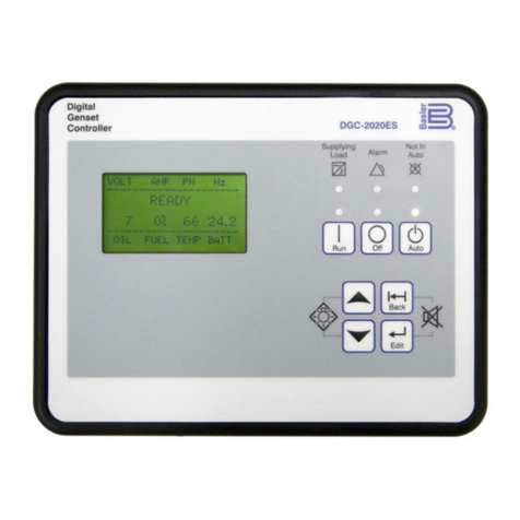
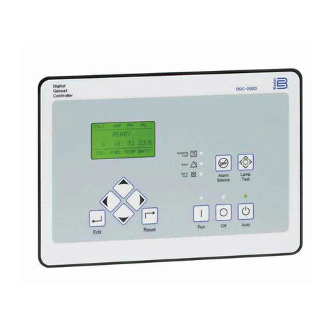
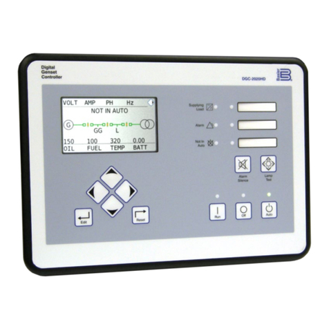
Basler DGC-2020ES Quick guide

12570 Route 143 •Highland, Illinois 62249-1074 USA
Tel +1 618.654.2341 •Fax +1 618.654.2351
Publication
9469200995, Rev B
December 2019
DGC-2020ES
Digital Genset Controller
Configuration Instruction Manual

WARNING: California's Proposition 65 requires special warnings for
products that may contain chemicals known to the state of California to
cause cancer, birth defects, or other reproductive harm. Please note that
by posting this Proposition 65 warning, we are notifying you that one or
more of the Proposition 65 listed chemicals may be present in products
we sell to you. For more information about the specific chemicals found
in this product, please visit https://www.basler.com/Prop65.

9469200995 i
DGC-2020ES Preface
Preface
This instruction manual provides information about the configuration of the DGC-2020ES Digital Genset
Controller. To accomplish this, the following information is provided:
•Device information and security settings
•Configuration via BESTCOMSPlus®and the front panel
•Communication settings
•Timekeeping
•Inputs and outputs
•Breaker management, synchronizer, bias control, and multiple generator management
•Alarm configuration
•Protection settings
•BESTlogic™Plus programmable logic
•Troubleshooting
Conventions Used in this Manual
Important safety and procedural information is emphasized and presented in this manual through
Warning, Caution, and Note boxes. Each type is illustrated and defined as follows.
Warning!
Warning boxes call attention to conditions or actions that may cause
personal injury or death.
Caution
Caution boxes call attention to operating conditions that may lead to
equipment or property damage.
Note
Note boxes emphasize important information pertaining to Digital
Genset Controller installation or operation.
DGC-2020ES Instruction Manual Catalog
Available instruction manuals for the DGC-2020ES are listed in Table 1.
Table 1. Instruction Manuals
Part Number
Description
9469200993
Quick Start
9469200994
Installation
9469200995
Configuration (this manual)
9469200996
Operation
9469200997
Accessories

ii 9469200995
Preface DGC-2020ES
12570 State Route 143
Highland IL 62249-1074 USA
www.basler.com
info@basler.com
Tel: +1 618.654.2341
Fax: +1 618.654.2351
© 2019 by Basler Electric
All rights reserved
First printing: April 2017
Warning!
READ THIS MANUAL.
Read this manual before installing, operating, or maintaining the DGC-2020ES.
Note all warnings, cautions, and notes in this manual as well as on the product. Keep this manual with
the product for reference. Only qualified personnel should install, operate, or service this system.
Failure to follow warning and cautionary labels may result in personal injury or property damage.
Exercise caution at all times.
Basler Electric does not assume any responsibility to compliance or noncompliance with national code, local code,
or any other applicable code. This manual serves as reference material that must be well understood prior to
installation, operation, or maintenance.
For terms of service relating to this product and software, see the Commercial Terms of Products and Services
document available at www.basler.com/terms.
This publication contains confidential information of Basler Electric Company, an Illinois corporation. It is loaned for
confidential use, subject to return on request, and with the mutual understanding that it will not be used in any
manner detrimental to the interests of Basler Electric Company and used strictly for the purpose intended.
It is not the intention of this manual to cover all details and variations in equipment, nor does this manual provide
data for every possible contingency regarding installation or operation. The availability and design of all features
and options are subject to modification without notice. Over time, improvements and revisions may be made to this
publication. Before performing any of the following procedures, contact Basler Electric for the latest revision of this
manual.
The English-language version of this manual serves as the only approved manual version.

9469200995 iii
DGC-2020ES Revision History
Revision History
A historical summary of the changes made to this instruction manual is provided below. Revisions are
listed in reverse chronological order.
Visit www.basler.com to download the latest hardware, firmware, and BESTCOMSPlus®revision
histories.
Instruction Manual Revision History
Manual
Revision and Date Change
B, Dec-19
•Removed Rev Letter from all pages.
•Changed sequential numbering to sectional numbering.
•Moved Instruction Manual Revision History into Preface.
•Removed standalone Revision History chapter. (Revision histories
for hardware, firmware, and software are now in separate documents
on www.basler.com.)
•Added support for firmware version 1.04.00 and BESTCOMSPlus
version 4.01.00.
A1, Apr-19
•Updated Proposition 65 statement
A, Sep-18
•Added description of voltage sensing fail function in the Engine
Sender Inputs chapter
•Updated Revision History chapter
—, Apr-17
•Initial release

iv 9469200995
Revision History DGC-2020ES

9469200995 v
DGC-2020ES Contents
Contents
Security ...................................................................................................................................................... 1-1
Configuration through the Front Panel....................................................................................................... 2-1
BESTCOMSPlus®...................................................................................................................................... 3-1
Communication .......................................................................................................................................... 4-1
Device Configuration.................................................................................................................................. 5-1
Timekeeping............................................................................................................................................... 6-1
Engine Sender Inputs................................................................................................................................. 7-1
Contact Inputs ............................................................................................................................................ 8-1
Contact Outputs ......................................................................................................................................... 9-1
Breaker Management............................................................................................................................... 10-1
Alarm Configuration ................................................................................................................................. 11-1
Generator Protection................................................................................................................................ 12-1
BESTlogic™Plus ...................................................................................................................................... 13-1
Exhaust Treatment................................................................................................................................... 14-1
Troubleshooting ....................................................................................................................................... 15-1
BESTCOMSPlus Settings Loader Tool.................................................................................................... 16-1

vi 9469200995
Contents DGC-2020ES

9469200995 1-1
DGC-2020ES Security
1 • Security
Password protection guards against unauthorized changing of DGC-2020ES settings. Three levels of
password protection are available. Each level is described in the following paragraphs.
•OEM Access. This password level allows access to all settings. The default, OEM-access password
is OEM.
•Settings Access. This password level allows all except uploading of firmware and clearing of device
event log. The default, settings-access password is SET.
•Operator Access. The default, operator-access password is OP. This password level allows all
settings to be read and allows changes to be made to the following:
oLCD Contrast
oSleep Mode
oDate/Time
oAll Sender Fail Time Delays
oMetric Conversion
oLow Fuel Pre-Alarm Level
oLow Fuel Alarm Level
oPre-Start Contact after Cranking
oCooldown Time
oPre-Crank Time Delay
oReset of Maintenance Interval
oAll controls on the Control screen available via the Metering Explorer in BESTCOMSPlus®
Changing Passwords
Passwords can be changed only after communication between the PC and DGC-2020ES is established.
Changes to passwords are made through the Device Security Setup screen. Use the Settings Explorer in
BESTCOMSPlus to open the General Settings, Device Security Setup screen.
The content of the Device Security Setup screen depends on the password level used when accessing
the screen. For example, someone logged in with a settings-access password will be able to change only
the settings-access and operator-access passwords - not the OEM-access password.
The BESTCOMSPlus Device Security Setup screen is illustrated in Figure 1-1. All three access levels are
shown.
A password is changed by clicking on the access level, entering the new password, and then clicking on
the Save Password button. DGC-2020ES passwords are case sensitive.
Saving Passwords in a DGC-2020ES Settings File
The passwords can be modified while BESTCOMSPlus is connected to a DGC-2020ES. The settings
from the BESTCOMSPlus session can then be saved into a settings file. The settings file will contain the
new passwords. Also, the passwords in a settings file can be modified off line, saved with the file, and
then later loaded into a DGC-2020ES.
Saving Passwords to a Settings File when On Line
The following procedure describes how to save passwords to a settings file when BESTCOMSPlus is
connected to a DGC-2020ES (on line):
1. When connected to a DGC-2020ES with BESTCOMSPlus, click on SETTINGS EXPLORER >
GENERAL SETTINGS > DEVICE SECURITY.
2. You will be prompted to enter a password.

1-2 9469200995
Security DGC-2020ES
3. Enter a password that is of a level as high as or higher than the password you wish to modify.
BESTCOMSPlus will display all passwords of a level equal to and below the level of the password
that was entered.
4. Click on the password you wish to modify. Type in the new password under the “Password” setting
that became active when the password to modify was clicked.
5. Click the “Save” button to save the new password into BESTCOMSPlus memory (it’s not in the DGC-
2020ES yet).
6. Repeat steps 4 and 5 for all password levels you with to modify.
7. Once all password modifications are complete, in the main menu of BESTCOMSPlus, select Upload
Security from the Communications pull-down menu. This is the step where passwords are sent to the
DGC-2020ES. Failure to perform this step might cause all password modifications to be lost.
8. Close the Device Security tab in BESTCOMSPlus.
9. Re-open the Device Security tab in BESTCOMSPlus. This will read the passwords back out of the
DGC-2020ES.
10. Verify the passwords obtained from the DGC-2020ES are correct.
11. Once all desired settings have been loaded into the DGC-2020ES, save the settings file. The
resulting settings file has the passwords saved as part of the saved settings.
12. At this point, the password information has been successfully saved in the settings file. The process
of saving the passwords into the settings file is complete.
Saving Passwords to a Settings File when Off Line
The following procedure describes how to save passwords to a settings file when working off line:
1. When the settings file is open in BESTCOMSPlus, click on SETTINGS EXPLORER > GENERAL
SETTINGS > DEVICE SECURITY.
2. You will be prompted to enter a password.
3. Enter a password that is of a level as high as or higher than the password you wish to modify.
BESTCOMSPlus will display all passwords of a level equal to and below the level of the password
that was entered.
4. Click on the password you wish to modify. Type in the new password under the “Password” setting
that became active when the password to modify was clicked.
5. Click the “Save” button to save the new password into BESTCOMSPlus memory.
6. Repeat steps 4 and 5 for all password levels you wish to modify.
7. Close the Device Security tab in BESTCOMSPlus.
8. Save the settings file.
9. Close the settings file by clicking on the X in the upper right-hand corner of the settings file, or close
BESTCOMSPlus.
10. Restart BESTCOMSPlus if you have shut it down.
11. Re-open the settings file that you have saved with the password information.
12. When the settings file is open in BESTCOMSPlus, click on SETTINGS EXPLORER > GENERAL
SETTINGS > DEVICE SECURITY.
13. You will be prompted to enter a password.
14. Enter the password for the highest level of password modified; it should be the new modified
password.
15. When passwords are shown, verify they are correct.
9469200995 1-3
DGC-2020ES Security
16. At this point the password information has been successfully saved in the settings file. The process of
saving the passwords into the settings file is complete.
Loading Passwords from a Settings File into the DGC-2020ES
1. Connect to the DGC-2020ES with BESTCOMSPlus.
2. Once connected, click the “Open File” button that is used to load a settings file into the DGC-2020ES.
3. You will be prompted asking if you wish to load settings and logic into the DGC-2020ES. Select Yes if
you need to upload settings logic. Select No if all you need to do is update security. If you select No,
the settings file opens into BESTCOMSPlus memory.
4. Whether you have loaded settings and logic to the DGC-2020ES or not, the next step is to select
Upload Security from the Communications pull-down menu.
5. DO NOT try to view the passwords before performing step 4. This would download the existing
passwords from the DGC-2020ES and they will overwrite the new passwords that were loaded into
BESTCOMSPlus memory from opening the settings file.
6. If you are prompted for a password, enter a password of a level equal to that of the highest-level
password you wish to modify.
7. The passwords are uploaded to the DGC-2020ES.
8. After you have uploaded the new passwords, select GENERAL SETTINGS > DEVICE SECURITY
SETUP in the settings explorer of BESTCOMSPlus. Verify the passwords are correct.
9. This concludes loading passwords from a settings file into the DGC-2020ES.
Figure 1-1. Settings Explorer, General Settings, Device Security Setup Screen

1-4 9469200995
Security DGC-2020ES

9469200995 2-1
DGC-2020ES Configuration through the Front Panel
2 • Configuration through the Front Panel
This chapter provides information on configuring DGC-2020ES settings through the front panel.
Display Setup
The DGC-2020ES LCD can be customized to fit the needs of your specific application. The options can
be adjusted using the front panel controls and through BESTCOMSPlus®. The display options are
described below.
The Front Panel HMI screen is found in the BESTCOMSPlus®Settings Explorer under the General
Settings category. If using the front panel, navigate to Settings > General Settings > Front Panel HMI.
Figure 2-1 shows the BESTCOMSPlus®Front Panel HMI settings screen.
1. LCD Contrast - Adjust this setting to reach the desired level of LCD contrast.
2. Front Panel Sleep Mode - Select Enable to send the DGC-2020ES into sleep mode. In sleep
mode, the LEDs and LCD backlight turn off after 15 minutes of inactivity on the front panel to
minimize battery drain.
3. One Line Diagram Display Enable - Select Enable to display one-line diagram.
4. Engine Hours Display – When Engine Hours Display is enabled, engine run-time hours are
displayed on the front-panel Overview screen.
5. Overview Screen Type – The Overview Screen Type can be set for Text or Symbolic. When set
to Symbolic, the parameters names are displayed as symbols.
6. Exhaust Display – When Exhaust Display is set to Inverted, the LCD background, where exhaust
status is displayed, is dark with light text. When set to Normal, the LCD background is light with
dark text.
7. Exhaust Status Display Screen – The Exhaust Status Display Screen setting defines where DEF
level and exhaust status display are shown. Select Overview Screen to show the DEF level and
exhaust status display on the Overview screen or select All Operating Screens to show the DEF
level and exhaust status display on all screens that automatically appear during normal operation.
8. Battery Charger Display – When Battery Charger Display is enabled, battery charger output
voltage and current are displayed on the front-panel Overview screen.
9. Display Fuel Level Below – Adjust this setting to display fuel level on the front-panel Overview
screen only when the fuel level is below the desired value. When fuel level is not displayed,
engine RPM is displayed in its place.
10. Language Selection - Select from Chinese, English, French, German, or Spanish.
11. Scrolling Screens - Specify the parameters which are to appear on the front-panel LCD display.
a. Configure the Configurable HMI Summary Settings.
b. Set the Scrolling Screen Enable to Enable.
c. Set the Scrolling Screen Scroll Delay parameter to the desired value.
12. Phase Toggle Delay - Set the phase toggle delay to a nonzero value if automatic scrolling
through the phase information in the standard overview screen on the front panel is desired. If it is
left at zero, scrolling through phase information is accomplished using the up and down arrow
buttons.
13. Initializing Message 1 - This parameter defines the first line of text that appears on the front panel
of the DGC-2020ES as it is going through its power up and initializing sequence.
14. Initializing Message 2 - This parameter defines the second line of text that appears on the front
panel of the DGC-2020ES as it is going through its power up and initializing sequence.

2-2 9469200995
Configuration through the Front Panel DGC-2020ES
Figure 2-1. Settings Explorer, General Settings, Front Panel HMI Screen
Settings Menu
The display structure of the Settings menu on the front panel is provided below. Refer to the Controls and
Indicators chapter in the Operation manual for a full description of DGC-2020ES controls and indicators.
GENERAL SETTINGS
●FRONT PANEL HMI
○SUMMARY VIEW
○SCROLL DELAY
○PH TOG DELAY
○LCD CONTRAST
○SLEEP MODE
○LANGUAGE
○CONFIGURABLE METERING
■ITEM X (X = 1 to 20)
○ONE LINE DIAGRAM
○ENG HRS DISPLAY
○OVERVIEW
○EXH DISPLAY
○EXH DISPL SCRN
○BATT CHG DISPLAY
○FUEL LVL DISPLAY

9469200995 2-3
DGC-2020ES Configuration through the Front Panel
●CONFIGURE DATE/TIME
○YEAR
○MONTH
○DAY
○HOURS
○MINUTES
○SECONDS
○UTC OFFSET
○DST ENABLED
○CLK NOT SET WRN
●VIEW DATE/TIME
●VERSION INFO
○DGC-2020ES
■FIRMWARE VERSION
■BOOT CODE VERSION
■SERIAL NUMBER
■PART NUMBER
■MODEL NUMBER
■LANGUAGE VERSION
■LANGUAGE PART NUM
■FONT VERSION
■FONT PART NUM
■STYLE CODE
○CEM-2020 (Visible when CEM-2020 is enabled.)
■FIRMWARE VERSION
■BOOT CODE VERSION
■SERIAL NUMBER
■PART NUMBER
■MODEL NUMBER
■BUILD DATE
COMMUNICATIONS
∗
∗(Visible when the optional J1939 CAN bus is enabled, style code xCx.)
●CAN BUS SETUP
○CAN BUS SETUP
■CAN BUS ENABLE
■DTC ENABLE (Visible when CAN BUS is enabled.)
■SPN CONV METHOD (Visible when CAN BUS is enabled.)
■CAN BUS ADDR (Visible when CAN BUS is enabled.)
■ENGINE ECU ADDRESS (Visible when CAN BUS is enabled.)
■ECU OPT SLCT (Visible when CAN BUS is enabled.)
■ECU PULSING (Visible when CAN BUS is enabled.)
■ENG SHTDN TM (Visible when CAN BUS is enabled.)
■PLS CYCL TM (Visible when CAN BUS is enabled.)
■ECU SET TM (Visible when CAN BUS is enabled.)
■RESP TIMEOUT (Visible when CAN BUS is enabled.)
■COOL TEMP SRC (Visible when CAN BUS is enabled.)
■OIL PRESS SRC (Visible when CAN BUS is enabled.)
■ENGINE RUN TM SRC (Visible when CAN BUS is enabled.)
○ECU SETUP (Visible when CAN BUS is enabled.)
■ECU CONF
■CUMMINS ECU SETUP
□CUMMINS GEN CONTROL
■ISUZU ECU SETUP
□CLEAR ECU MEMORY
□ESCAPE MODE
■YANMAR ECU SETUP
□NUMBER OF CYLINDERS
■GEN DATA TRANSMIT
■ENGINE PARAM XMT
■TRIP RESET (Visible when ECU is configured for Standard, Volvo Penta, MTU ADEC,
GM/Doosan, Cummins, or MTU Smart Connect.)
■START MODE

2-4 9469200995
Configuration through the Front Panel DGC-2020ES
■DPF REGENRATE SETUP (Visible when ECU is configured for Standard, Volvo Penta, MTU
ADEC, GM/Doosan, Cummins, or MTU Smart Connect.)
□DPF MANUAL REGEN
□DPF REGEN DISABLE
■BATT CHARGER SETUP
□CHARGER 1 TYPE
□CHARGER 2 TYPE
■BATT CHARGR PREALARMS
□CH1 COMMS FAIL
□CH1 BATTERY FAIL
□CH1 CHARGER FAIL
□CH1 AC OFF
□CH2 COMMS FAIL
□CH2 BATTERY FAIL
□CH2 CHARGER FAIL
□CH2 AC OFF
■SENS CHARGR PREALARMS
□CH1 THERMAL LIMIT (Visible when CHARGER 1 TYPE is set to SENS)
□CH1 HI DC VOLTS (Visible when CHARGER 1 TYPE is set to SENS)
□CH1 LOW DC VOLTS (Visible when CHARGER 1 TYPE is set to SENS)
□CH1 LO CRANK V (Visible when CHARGER 1 TYPE is set to SENS)
□CH1 INVLD SETTINGS (Visible when CHARGER 1 TYPE is set to SENS)
□CH1 SNGL UNIT FL (Visible when CHARGER 1 TYPE is set to SENS)
□CH2 THERMAL LIMIT (Visible when CHARGER 2 TYPE is set to SENS)
□CH2 HI DC VOLTS (Visible when CHARGER 2 TYPE is set to SENS)
□CH2 LOW DC VOLTS (Visible when CHARGER 2 TYPE is set to SENS)
□CH2 LO CRANK V (Visible when CHARGER 2 TYPE is set to SENS)
□CH2 INVLD SETTINGS (Visible when CHARGER 2 TYPE is set to SENS)
□CH2 SNGL UNIT FL (Visible when CHARGER 2 TYPE is set to SENS)
■SPEED SELECT (Visible when ECU is configured for Volvo Penta.)
■ACCEL POSITION (Visible when ECU is configured for Volvo Penta.)
■MODULE TYPE (Visible when ECU is configured for MTU MDEC or MTU ECU7/ECU8.)
■ALIVE MSG (Visible when ECU is configured for MTU MDEC or MTU ECU7/ECU8.)
■SPEED SETUP
□J1939 RPM ENABLE (Visible when ECU is configured for Standard, Volvo Penta,
MTU ADEC, GM/Doosan, Cummins, or MTU Smart Connect.)
□ENGINE RPM
□SAVE RPM ADJUSTS
□RPM BAND WIDTH
□IDLE RPM
□RPM CHECKSUM
□SPEED UP (Visible when ECU is configured for MTU ADEC, MTU MDEC 304, MTU
ECU7/ECU8, or MTU Smart Connect.)
□SPEED DN (Visible when ECU is configured for MTU ADEC, MTU MDEC 304, MTU
ECU7/ECU8, or MTU Smart Connect.)
□TEST OVRSPEED (Visible when ECU is configured for MTU ADEC, MTU MDEC
304, MTU ECU7/ECU8, or MTU Smart Connect.)
□SPD DMAND SRC (Visible when ECU is configured for MTU ADEC, MTU MDEC
304, MTU ECU7/ECU8, or MTU Smart Connect.)
□IDLE REQUEST (Visible when ECU is configured for MTU MDEC 304, MTU
ECU7/ECU8, or MTU Smart Connect.)
□INCREASE IDLE (Visible when ECU is configured for MTU MDEC 304, or MTU
ECU7/ECU8.)
■ECU SETUP (Visible when ECU is configured for MTU ADEC, MTU MDEC 304, MTU
ECU7/ECU8, or MTU Smart Connect.)
□TRIP RESET (Visible when ECU is configured for MTU MDEC 304, or MTU
ECU7/ECU8.)
□INT OIL PRIME
□GOV PRM SW (Visible when ECU is configured for MTU ADEC or MTU Smart
Connect.)
□ENG STRT PRIME (Visible when ECU is configured for MTU MDEC 304, or MTU
ECU7/ECU8.)
□FAN OVERRIDE (Visible when ECU is configured for MTU MDEC 304, or MTU
ECU7/ECU8.)

9469200995 2-5
DGC-2020ES Configuration through the Front Panel
□MODE SWITCH (Visible when ECU is configured for MTU MDEC 304, or MTU
ECU7/ECU8.)
□GOV PARAM SET (Visible when ECU is configured for MTU ECU7/ECU8.)
□CAN RATING SW 1 (Visible when ECU is configured for MTU ECU7/ECU8.)
□CAN RATING SW 2 (Visible when ECU is configured for MTU ECU7/ECU8.)
□DIS CYL CUT 1 (Visible when ECU is configured for MTU MDEC 304, or MTU
ECU7/ECU8.)
□DIS CYL CUT 2 (Visible when ECU is configured for MTU MDEC 304, MTU
ECU7/ECU8 or MTU Smart Connect.)
□OPERATING MODE (Visible when ECU is configured for MTU Smart Connect.)
SYSTEM PARAMS
●SYSTEM SETTINGS
○GEN CONNECT
○BUS CONNECT
○RATED kW
○RATED VOLTS
○RATED FREQ
○ALTRNATE FRQ
○RATED RPM
○RATED PF
○ROTATION
○EPS
■EPS THRESHLD
■LOW LINE SF (Visible when an input is selected for the Low Line Override programmable
function.)
○FUEL LVL TYP
○SYSTEM UNITS
○PRESSURE UNITS (Visible when Metric is selected for System Units.)
○BATTERY VOLT
○FLYWHL TEETH
○SPEED SOURCE
○MAINT RESET
○NFPA LEVEL
○POWER UP DELAY
●REMOTE MODULE SETUP
○CEM SETUP
■ENABLE
■OUTPUTS (Visible when CEM-2020 is enabled.)
■CAN BUS ADDR (Visible when CEM-2020 is enabled.)
■VERSION INFO (Visible when CEM-2020 is enabled.)
□FIRMWARE VERSION
□BOOT CODE VERSION
□SERIAL NUMBER
□PART NUMBER
□MODEL NUMBER
□BUILD DATE
■CEM DEBUG MENU (Visible when CEM-2020 is enabled.)
□DGC TO CEM BP
□CEM TO DGC BP
●CRANK SETTINGS
○DISCNCT LMIT
○PRECRNK DELY
○PRESTRT CNTCT
○STYLE
○# CYCLES (Visible when Cycle is selected for Cranking Style.)
○CONT TIME (Visible when Continuous is selected for Cranking Style.)
○CYCLE TIME
○REST TIME
○COOLDWN TIME
○COOLDOWN CONFIG
○RESTART DELAY
○OFF MODE COOLDN

2-6 9469200995
Configuration through the Front Panel DGC-2020ES
○PRESTART REST CONFIG
■CONF
○OIL PRS CRANK DISC
■ENABLE
■CRANK DISC PRS
●AUTOMATIC RESTART
○ENABLE
○ATTEMPTS
○INTERVAL
●EXERCISE TIMER
○MODE
○RUN WITH LOAD
○START HOUR
○START MINUTE
○RUN HOURS
○RUN MINUTES
●SENSING TRANS
○GEN PT PRI V
○GEN PT SEC V
○GEN CT PRI A
○CT LOW LINE SF (Visible when an input is selected for the Low Line Override programmable function.)
○BUS PT PRI V
○BUS PT SEC V
●RELAY CONTROL
○START
○RUN
○PRESTART
●AUTO CONFIG DETECT
○ENABLE
○LOW LINE THRESH
○1-PH THRESH
○1-PH GEN CONN
●ENGINE STATISTICS
○START YEAR
○START MONTH
○START DAY
○# STARTS
○HRS TO MAINT
○kW-HRS
○TOTAL HRS
○LOADED HRS
○UNLOADED HRS
PROGRAMMABLE INPUTS
●CONFIGURABLE INPUTS
○INPUT X (X = 1 to 7)
■ALARM CONFIG
■ACTIVATN DLY
■RECOGNITION
●PROG FUNCTIONS
○EMERGENCY STOP
■INPUT
○AUTO XFER SWITCH
■INPUT
■RECOGNITION (Visible when an INPUT is selected.)
○GRND DELTA O-RIDE
■INPUT
■RECOGNITION (Visible when an INPUT is selected.)
○BATTLE OVERRIDE
■INPUT
■RECOGNITION (Visible when an INPUT is selected.)
○LOW LINE OVERRIDE
■INPUT
■RECOGNITION (Visible when an INPUT is selected.)

9469200995 2-7
DGC-2020ES Configuration through the Front Panel
○1 PHASE O-RIDE
■INPUT
■RECOGNITION (Visible when an INPUT is selected.)
○BATT CHRG FAIL
■INPUT
■ALARM CONFIG (Visible when an INPUT is selected.)
■ACTIVATN DLY (Visible when an INPUT is selected.)
■RECOGNITION (Visible when an INPUT is selected.)
○LOW COOL LEVEL
■INPUT
■ALARM CONFIG (Visible when an INPUT is selected.)
■ACTIVATN DLY (Visible when an INPUT is selected.)
■RECOGNITION (Visible when an INPUT is selected.)
○LOW FUEL LEVEL
■INPUT
■ALARM CONFIG (Visible when an INPUT is selected.)
■ACTIVATN DLY (Visible when an INPUT is selected.)
■RECOGNITION (Visible when an INPUT is selected.)
○FUEL LEAK DETECT
■INPUT
■ALARM CONFIG (Visible when an INPUT is selected.)
■ACTIVATN DLY (Visible when an INPUT is selected.)
■RECOGNITION (Visible when an INPUT is selected.)
PROGRAMMABLE OUTPUTS
●CONFIG ELEMENTS
○CONFIG ELEMENT X (X = 1 to 8)
■ALARM CONFIG
■ACTIVATN DLY
■RECOGNITION
ALARM CONFIGURATION
●HORN CONFIGURATION
○HORN
○NOT IN AUTO HORN
●PRE-ALARMS
○HIGH COOLANT TEMP
■ENABLE
■THRESHOLD
○LOW COOLANT TEMP
■ENABLE
■THRESHOLD
○LOW OIL PRESSURE
■ENABLE
■THRESHOLD
○LOW FUEL LEVEL
■ENABLE
■THRESHOLD
■HYSTERESIS
○ENGINE OVERLOAD
■ENG KW OVRLD-1
■ENG KW OVRLD-2
■ENG KW OVRLD-3
○MAINTENANCE INTERVAL
■ENABLE
■THRESHOLD
○BATTERY OVERVOLTAGE
■ENABLE
■THRESHOLD
○LOW BATTERY VOLTAGE
■ENABLE
■THRESHOLD
■ACTIVATN DLY

2-8 9469200995
Configuration through the Front Panel DGC-2020ES
○WEAK BATTERY VOLTAGE
■ENABLE
■THRESHOLD
■ACTIVATN DLY
○HIGH FUEL LEVEL
■ENABLE
■THRESHOLD
■ACTIVATN DLY
■HYSTERESIS
○ACTIVE DTC (Visible when DTC is enabled.)
■ENABLE
○ECU COMMS FAIL (Visible when CAN BUS is enabled.)
■ENABLE
○COOLANT LEVEL (Visible when CAN BUS is enabled.)
■ENABLE
■THRESHOLD
○CEM COMM FAIL (Visible when CEM-2020 is enabled.)
■ENABLE
○CHECKSUM FAIL
■ENABLE
○BRK CLOSE FAIL PALM
■ENABLE
○BRK OPEN FAIL PALM
■ENABLE
○REVERSE ROTATION
■ENABLE
•ALARMS
○HIGH COOLANT TEMP
■ENABLE
■THRESHOLD
■ARMING DELAY
○LOW OIL PRESSURE
■ENABLE
■THRESHOLD
■ARMING DELAY
○LOW FUEL LEVEL
■ENABLE
■THRESHOLD
■ACTIVATN DLY
○OVERSPEED
■ENABLE
■THRESHOLD
■ACTIVATN DLY
○COOLANT LEVEL (Visible when CAN bus is enabled.)
■ENABLE
■THRESHOLD
○CAN LOW COOL LEVEL
Note
The HIGH COOLANT TEMP and LOW OIL PRESSURE alarms have
an ARMING DLY setting that disables the alarm for the specified time
after engine startup.
●SENDER FAIL
○COOL TEMP SENDR FAIL
■CONFIG TYPE
■RECOGNITION
■ACTIVATN DLY
■MIN OHMS
■MAX OHMS
■SF DISPLAY
○OIL PRESS SENDR FAIL
■CONFIG TYPE
■RECOGNITION
Other manuals for DGC-2020ES
2
Table of contents
Other Basler Controllers manuals

Basler
Basler DGC-2020HD Service manual

Basler
Basler SR6A User manual

Basler
Basler AVC63-12A1 User manual

Basler
Basler DGC-2020ES User manual

Basler
Basler AEC 42-7 User manual

Basler
Basler SSR 32-12 User manual

Basler
Basler AVC63-12 User manual

Basler
Basler DGC-2020ES User manual

Basler
Basler APR 63-5 User manual

Basler
Basler AVC63-4A User manual

Basler
Basler SR4A User manual

Basler
Basler AVC63-4 User manual

Basler
Basler AVC634A-12 User manual

Basler
Basler DECS-250 User manual

Basler
Basler BE2000E User manual

Basler
Basler DGC-2020 User manual

Basler
Basler AVC63-2 User manual

Basler
Basler KR4FFX User manual

Basler
Basler DECS-200 User manual

Basler
Basler DGC-500 User manual