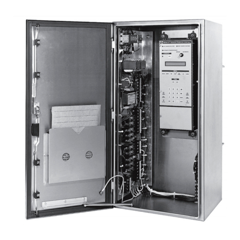
S&C 5800 Series Operating instructions

S&C 5800 Series Automatic Switch Control
Instruction Sheet 1041-550
July 5, 2011© S&C Electric Company
Troubleshooting
Table of Contents
Section Page Section Page
Introduction
Qualified Persons . . . . . . . . . . . . . . . . . . . . . . . . . . .2
Read this Instruction Sheet . . . . . . . . . . . . . . . . . . .2
Retain this Instruction Sheet . . . . . . . . . . . . . . . . . . .2
Warranty . . . . . . . . . . . . . . . . . . . . . . . . . . . . . . . . . .2
Safety Information
Understanding Safety-Alert Messages . . . . . . . . . . .3
Following Safety Instructions. . . . . . . . . . . . . . . . . . .3
Replacement Instructions and Labels . . . . . . . . . . . .3
IntelliLINK®Software
Applicable Software. . . . . . . . . . . . . . . . . . . . . . . . . .4
Troubleshooting Overview. . . . . . . . . . . . . . . . . . . . .5
Power Problems . . . . . . . . . . . . . . . . . . . . . . . . . . . .6
LCD Problems . . . . . . . . . . . . . . . . . . . . . . . . . . . . .6
Software Troubleshooting and Error Messages
Starting IntelliLINK. . . . . . . . . . . . . . . . . . . . . . . . . . .9
Miscellaneous Problems . . . . . . . . . . . . . . . . . . . . .12
IntelliLINK
Using IntelliLINK to Locate Problems . . . . . . . . . . .14
Event Status . . . . . . . . . . . . . . . . . . . . . . . . . . . . . .16
Chronological Log . . . . . . . . . . . . . . . . . . . . . . . . . .20
Control and Switch Information . . . . . . . . . . . . . . . .20
Switch Operations . . . . . . . . . . . . . . . . . . . . . . . . . .22
Communications . . . . . . . . . . . . . . . . . . . . . . . . . . .24
Various Counters . . . . . . . . . . . . . . . . . . . . . . . . . . .27
Receive Interrupt Counts. . . . . . . . . . . . . . . . . . . . .28
Application Layer Counts. . . . . . . . . . . . . . . . . . . . .29
Data Link Layer Counts . . . . . . . . . . . . . . . . . . . . . .30
Battery System . . . . . . . . . . . . . . . . . . . . . . . . . . . .31

2S&C Instruction Sheet 1041-550
Introduction
Qualified Persons
Read this
Instruction Sheet
Retain this
Instruction Sheet
Warranty
ÇWARNING
The equipment covered by this publication must be installed, operated, and main-
tained by qualified persons who are knowledgeable in the installation, operation,
and maintenance of overhead electric power distribution equipment along with the
associated hazards.
A qualified person is one who is trained and competent in:
• The skills and techniques necessary to distinguish exposed live parts from non-
live parts of electrical equipment.
• The skills and techniques necessary to determine the proper approach distances
corresponding to the voltages to which the qualified person will be exposed.
• The proper use of the special precautionary techniques, personal protective
equipment, insulating and shielding materials, and insulated tools for working on
or near exposed energized parts of electrical equipment.
These instructions are intended only for such qualified persons. They are not
intended to be a substitute for adequate training and experience in safety procedures
for this type of equipment.
Thoroughly and carefully read this instruction sheet before programming, operating, or
maintaining your S&C 5800 Series Automatic Switch Control. Familiarize yourself with the
safety information on page 3. The latest version of this instruction sheet is available online
in PDF format at www.sandc.com. Select: Support/Product Literature Library.
This instruction sheet is a permanent part of your S&C 5800 Series Automatic Switch Control.
Designate a location where you can easily retrieve and refer to this publication.
The standardwarrantycontained inS&C’s standard conditionsofsale, assetforth inPriceSheets
150 and 181, applies to the S&C 5800 Series Controls, except that the first paragraph of said
warranty is replaced by the following:
(1) General: Seller warrants to immediate purchaser or end user for a period of
10 years from the date of shipment that the equipment delivered will be of the kind and
quality specified in the contract description and will be free of defects of workmanship and
material. Should any failure to conform to this warranty appear under proper and normal
use within ten years after the date of shipment the seller agrees, upon prompt notification
thereof and confirmation that the equipment has been stored, installed, operated, inspected,
and maintained in accordance with recommendations of the seller and standard industry
practice, to correct the nonconformity either by repairing any damaged or defective parts
of the equipment or (at seller’s option) by shipment of necessary replacement parts. The
seller’s warranty does not apply to any equipment that has been disassembled, repaired,
or altered by anyone other than the seller. This limited warranty is granted only to the
immediate purchaser or, if the equipment is purchased by a third party for installation in
third-party equipment, the end user of the equipment. The seller’s duty to perform under
any warranty may be delayed, at the seller’s sole option, until the seller has been paid in
full for all goods purchased by the immediate purchaser. No such delay shall extend the
warranty period.
Replacement parts provided by seller or repairs performed by seller under the warranty
for the original equipment will be covered by the above special warranty provision for its
duration. Replacement parts purchased separately will be covered by the above special
warranty provision.
Warranty of S&C 5800 Series Automatic Switch Controls is contingent upon the installa-
tion, configuration, and use of the control or software in accordance with S&C’s applicable
instruction sheets.
This warranty does not apply to major components not of S&C manufacture, such as
batteries, and communication devices. However, S&C will assign to immediate purchaser
or end user all manufacturer’s warranties that apply to such major components.
S&C Instruction Sheet 1041-550 3
Safety Information
Understanding
Safety-Alert Messages
Following
Safety Instructions
Replacement
Instructions and Labels
There are several types of safety-alert messages which may appear throughout this
instruction sheet as well as on labels attached to the 5800 Series Control. Familiarize
yourself with these types of messages and the importance of the various signal words,
as explained below.
ÇDANGER
“DANGER” identifies the most serious and immediate hazards which will likely
result in serious personal injury or death if instructions, including recommended
precautions, are not followed.
ÇWARNING
“WARNING” identifies hazards or unsafe practices which can result in serious
personal injury or death if instructions, including recommended precautions, are
not followed.
ÇCAUTION
“CAUTION” identifies hazards or unsafe practices which can result in minor per-
sonal injury or product or property damage if instructions, including recommended
precautions, are not followed.
NOTICE
“NOTICE” identifies important procedures or requirements that can result in product
or property damage if instructions are not followed.
If you do not understand any portion of this instruction sheet and need assistance,
contact your nearest S&C Sales Office or S&C Authorized Distributor. Their tele-
phone numbers are listed on S&C’s website www.sandc.com. Or call S&C Headquarters
at (773) 338-1000; in Canada, call S&C Electric Canada Ltd. at (416) 249-9171.
NOTICE
Read this instruction sheet thoroughly and carefully
before installing or operating your S&C 5800 Series
Automatic Switch Control.
If you need additional copies of this instruction sheet, contact your nearest S&C Sales
Office, S&C Authorized Distributor, S&C Headquarters, or S&C Electric Canada Ltd.
It is important that any missing, damaged, or faded labels on the equipment be replaced
immediately. Replacement labels are available by contacting your nearest S&C Sales Office,
S&C Authorized Distributor, S&C Headquarters, or S&C Electric Canada Ltd.

4S&C Instruction Sheet 1041-550
ÇWARNING
These instructions do not replace the need for utility operation standards. Any
conflict between the information in this document and utility practices should be
reviewed by appropriate utility personnel and a decision made as to the correct
procedures to follow.
Serious risk of personal injury or death may result from contact with electric
distribution equipment when electrical isolation and grounding procedures are not
followed. The equipment described in this document must be operated and main-
tained by qualified persons who are thoroughly trained and understand any hazards
that may be involved. This document is written only for such qualified persons and
is not a substitute for adequate training and experience in safety procedures for
accessing high-voltage equipment.
The S&C 5800 Series Automatic Switch Control is connected to switchgear oper-
ating at primary voltage levels. High voltage may be present in the wiring to the
switch control or the switch control itself during certain failures of the switchgear
wiring or grounding system, or due to a failure of the switch itself. For this reason,
access to the switch control should be treated with the same safety precautions that
would be applied when accessing other high-voltage lines and equipment. Follow all
locally-approved safety procedures when working on or around this switch control.
Before attempting to access an existing switch installation, check carefully for
visible or audible signs of electrical or physical malfunction (do this before touching
or operating the switch control or any other part of the installation). These warning
signs include such things as smoke, fire, open fuses, crackling noises, loud buzzing,
etc. If a malfunction is suspected, treat all components of the installation, including
the switch control and associated mounting hardware, as if they were elevated to
primary (high) voltage.
Whenever you are manually reconfiguring the circuit (for example, during repairs),
follow your company’s operating procedures to disable automatic operation of the
S&C 5800 Series Automatic Switch Control. This prevents any unexpected operation.
Applicable Software This instruction sheet was prepared for use with all stand-alone (not IntelliTEAM®
or IntelliTEAM II®) 5800 Series Software available November 2008: DNP Protocol:
SNCD2S0V Rev. 2.42, PADD2S0X Rev. 2.44, USBD2S0X Rev. 2.40, UDSD2S0X Rev.
2.26 PG&E Protocol: SNCP0S0X Rev. 2.21, USBP0S0X Rev. 2.29, UDSP0S0X Rev.
2.32 Intrac Protocol: SNCI0S0X Rev. 2.18, USBI0S0X 2.30.
Software Available December 2010: DNP Protocol: SNCD2S0X Rev. 2.45.
The revision number is on the setup disk label and on the IntelliLINK software TROUBLE-
SHOOTING: Control & Switch Information screen. For questions regarding the applicabil-
ity of information in this instruction sheet to future product releases, please contact S&C.
IntelliLINK Software

S&C Instruction Sheet 1041-550 5
Troubleshooting Overview
The following tools and switch control features are used to diagnose and correct problems.
LCD
The LCD on the switch control faceplate provides information about the present state of
the switch control. For an explanation of the faceplate and the LCD, see The Faceplate in
S&C Instruction Sheet 1041-540.
LEDs
The LEDs on the switch control modules and the faceplate provide information about the
present state of the control. (For an explanation of the faceplate and the Power Supply/
Control I/O LEDs, see S&C Instruction Sheet 1041-540.)
The IntelliLINK software
The OPERATION screens and TROUBLESHOOTING screens display information about
the switch control, switch control operations, and switch sensor data. For an explanation
of these screens, see Using IntelliLINK Software to Locate Problems on page 15.
To view these screens, you need a portable IBM/PC-compatible computer, a serial
cable, and the IntelliLINK version for this 5800 Series switch control. For more informa-
tion about the equipment required and how to use the IntelliLINK software, see S&C
Instruction Sheet 1041-530.
Electrical Interconnect Diagrams
The electrical interconnect diagrams, in S&C Instruction Sheet 1041-530, show the switch
control wiring layout.
Test Points
Most of the wiring in the switch control enclosure is terminated in insulation displacement
connectors. To test a pin, gently slide the black plastic cap sideways on the connector
until the pin is exposed. Test the pin, then replace the cap to protect the wiring from dust
and to prevent shorts. Avoid inserting the test probe into the connector receptacle as this
may damage the connector.
Figure 1. Switch Control with faceplate open.
WARNING!
Area containing 340 Vac
Switch control
electronics modules
Terminal block
Grounded ac outlet
(S&C 5801 only)
Communication
equipment on
mounting plate (optional)

6S&C Instruction Sheet 1041-550
Power Problems
Troubleshooting Overview
Hardware Tools
To correct a problem, you may need one or more of the following tools:
• Multimeter and probes
• 4⬙long, #2 Phillips screwdriver
• 4⬙long, 1/4⬙-blade screwdriver
NOTE: If the suggested troubleshooting steps do not resolve the problem, call S&C at
(800) 621-5546.
AC LINE fuse is blown
Replace the fuse. Swith the fuse holder open, replace the fuse, then push the fuse holder
back in place.
Battery does not supply power when ac power is off
See BAT ON LED (on PS/IO) is OFF on page 9.
Power Supply Control I/O is not providing power
See BAT ON LED (on PS/IO) is OFF on page 9.
LCD is blank or you cannot scroll the data
a. Check the LEDs. If all the switch control LEDs, including those on the PS/IO module,
are OFF the switch control is not receiving power. See AC ON LED (on PS/IO) is
OFF on page 7 and BAT LOW LED is OFF on page 9.
b. Check the faceplate circuit module connections. Check connectors J6 and J8. If one
of the connectors is loose, push it into place, then cycle power to the switch control.
To cycle power to the control, remove the AC LINE fuse, then disconnect the red and
black battery leads. Reconnect the battery, then reinsert the AC LINE fuse. If the LCD
still does not work, the LCD module may need to be replaced.
Backlighting on the LCD does not light
Do a lamp test. Hold the faceplate BATTERY TEST/LAMP TEST switch in the LAMP
TEST position. If the backlighting does not come on, but the LEDs blink, the toggle switch
or the LCD module may need to be replaced. If none of the LEDs blink, see All LEDs on
the faceplate are OFF on page 7.
All LEDs on the faceplate are OFF
Check the LCD for data. If the display contains data and you can scroll through it, the proces-
sor is powered and functioning. The problem is with the tamper switch for the door. Make
sure the magnet is present on the top inside of the enclosure door (S&C 5801) or on the
compartment door (S&C 5802/5803). Make sure that the wiring to the magnet is connected.
If the display is blank or you cannot scroll through the data, open the faceplate, remove
the cover from the faceplate circuit board, and check the red CPU Reset LED. The LED is
located on the component side of the board near the BATTERY TEST switch. If it is on,
the faceplate circuit board is bad; contact S&C.
Check the switch control power (+12 V). Check the AC ON and BAT ON LEDs. If nei-
ther is ON, the battery may be discharged. Press the BAT ON switch (on the left side of
the PS/IO, near the AC ON LED) to test this condition. Power will be restored for about
one minute if the battery is low and AC power, or sensor power if applicable, is off. If AC
power or sensor power is on, the battery can begin recharging.
LCD Problems

S&C Instruction Sheet 1041-550 7
Troubleshooting Overview
AC ON LED (on PS/IO) is OFF
a. Check for ac power to the switch control. Check for ac voltage between the incoming-
side test point of the AC LINE fuse holder and the ac neutral. See Figure 2.
b. For externally-powered controls, check the power line. Following utility-approved
work procedures and safety practices, verify that there is 120 Vac in the line which
provides ac power for the switch control.
c. Check the ac line and ac neutral wiring connections. Make sure the ac line wire is
securely connected to the bottom of the AC LINE fuse holder. See Figure 2. Make
sure the neutral wire is securely connected to the neutral lug.
d. To check the AC LINE fuse, do one of the following: (1) Swing the fuse holder open
and check the fuse for continuity with a multimeter; replace the fuse if it is bad, then
push the fuse holder back in place. (2) If 120 Vac is present at the incoming-side test
point, check for voltage at the fuse-side” test point. See Figure 2.
e. With all power sources disconnected, tighten the screws behind the AC LINE fuse.
Disconnect the ac power line and the battery. For sensor-powered controls, also
disconnect the external signal cable(s). Remove the AC LINE fuse. Tighten the two
screws that are normally hidden behind the fuse. Reinstall the fuse, then reconnect
all power sources.
f. Check the connection at PS/IO J17. Check that the ac power connector is plugged into
the PS/IO at J17.
g. For sensor-powered controls, check the voltage from the switch sensors.
ÇCAUTION
This is a high-voltage area of the PS/IO module. When checking the voltage, make
sure the 10-ampere AC LINE fuse and the 10-ampere dc wetting fuse are OUT and the
ac power line is de-energized. For switch controls powered from the sensors, you
must also disconnect the switch interface cable(s) on the bottom of the enclosure.
Check the dc voltage across PS/IO J8, pins 1 (positive) and 3. The voltage should be
between 280 and 340 Vdc.
NOTE: Do not unplug PS/IO J8.
AC Neutral
AC LINE
Figure 2. Test points for AC LINE Fuse and AC Neutral.

8S&C Instruction Sheet 1041-550
Troubleshooting Overview
ANALOG PWR LED (on PS/IO) is OFF or blinking
Call S&C. The PS/IO is malfunctioning.
BATTERY LOW LED is ON
See Battery Low on TROUBLESHOOTING: Event Status screen on page 18.
BATTERY LOW LED is OFF
a. Check the BATTERY LOW LED on the switch control faceplate. If the BATTERY
LOW LED is blinking, a battery test is in progress. The BAT ON LED (on the PS/IO)
normally turns off and on several times during a battery test.
b. Check that the battery leads are connected.
c. Disconnect all power sources, then check the wiring from the battery. Disconnect the
battery leads and the ac power line. For sensor-powered controls, also disconnect the
switch interface cable(s). On the PS/IO, check that the cables are connected at Bat
A1+, Bat A2-, +24VOUT or +35VOUT, and BATCOM. Tighten the screws that hold
these cables in place.
d. Replace the battery.
CHG ON LED (on PS/IO) is OFF
a. Check that a battery is present and connected to the switch control. The CHG ON
LED is always off when the battery is disconnected.
b. Check the BATTERY LOW LED on the switch control faceplate. If the BATTERY LOW
LED is blinking, a battery test is in progress. The CHG ON LED is always off during
battery tests.
c. Check for ac power to the switch control. (See AC ON LED (on PS/IO) is OFF on
page 7 for details.) The CHG ON LED is always off when ac power is off. For sensor-
powered controls, check PS/IO J8. For sensor powered controls check the voltage
from the sensors.
d. Check the battery voltage. Disconnect the battery. With a voltmeter, check that the
voltage is greater than 23 volts (for a 24 Vdc battery) or 35 volts (for a 36 Vdc battery).
If not, replace the battery.
e. Check the battery connections. Check that the battery leads are connected to the
battery and the PS/IO, and that the wires are not damaged.
f. The PS/IO module may be inoperative. Call S&C about replacing the module.
ERROR DETECTED LED (on the faceplate) is ON
Use IntelliLINK Software to check for troubleshooting messages. Connect your
portable computer to the switch control, and start the IntelliLINK Software program. Check
for Active messages on the TROUBLESHOOTING: Event Status screens. To correct the
problem, follow the troubleshooting suggestions for the listed error(s).
PROCESSOR STATUS LED (on faceplate) does not blink
Blinking is the normal state, and indicates that the processor is operating. The control
software commands this LED to be on or off. If blinking stops with the LED turned on,
you know for certain that the change command has stopped.
If the blinking stops with the LED turned off and other LEDs are illuminated, you also
need to check for a malfunction of the Processor Status LED. Do a lamp test. Hold
the faceplate BATTERY TEST/LAMP TEST switch in the LAMP TEST position. If the
Processor Status LED illuminates, you know that a change command has not occurred.

S&C Instruction Sheet 1041-550 9
Software Troubleshooting and Error Messages
Starting IntelliLINK The IntelliLINK software may display an error message while trying to establish com-
munications with the switch control or a snapshot (VM file). If an error message appears,
follow the corrective action given below for that message.
IntelliLINK software won’t start
a. Close other software programs. Some software applications (such as HotSync® for
Palm® handhelds) may interfere with IntelliLINK software being able to access your
computer’s serial port. You should exit any program that might take control of a serial
port, when you use the IntelliLINK software.
b. Reinstall the IntelliLINK software on your computer. There may be a problem with
one of the files. See To Install the IntelliLINK Software in the Setup Instruction Sheet
1041-530 for details.
“Could not connect to control on COM1”
See Opening port COM 1... Trying 38400 BAUD... Connection Failed below.
“Incompatible Ident”
The IntelliLINK software uses a different screenset (WMN file) for each type of control and
normally selects the screenset for you. This message appears when you have a screenset
displayed and try to connect to a snapshot (VM file) that requires a different screenset.
Use the correct screenset. To close the open screenset, click File > Close Screenset. Then
click Connection > Connect to VM file. In the Open Controller Data File dialog box, select
the snapshot you want to view, then click OK to open both the snapshot and the correct
screenset.
“IntelliLINK setup incorrect or incomplete“
Reinstall the IntelliLINK software on your computer. There may be a problem with one of
the files. See To Install the IntelliLINK Software in the Setup Instruction Sheet 1041- 530
for details.
“Opening port COM1... Trying 38400 BAUD... Connection Failed”
These messages appear in the Connect dialog box when the IntelliLINK software in your
computer cannot establish communication with the software in the switch control.
a. Check that the switch control has power. If the LCD is blank, the control may have
no power and cannot communicate with your portable computer. See LCD is blank
or you cannot scroll the data on page 6.
b. Check the serial cable connections. Check that you plugged your serial cable into the
LOCAL COMMUNICATIONS ACCESS port on the switch control faceplate. Check
that you plugged the cable into the correct port on your computer, usually COM1 on
portable computers.
c. Try another communications port. The COM1 port on your computer may be broken
or assigned to a different device. Connect the cable to another comm port. In the
Connect dialog box, click the Change Setup button. From the pull-down list, select
the name of the port where you connected the cable. Click Connect.
d. Use a different serial cable. The serial cable between your computer and the switch
control may have a broken wire or pin. The cable may be wired for use with a differ-
ent kind of computer, or it may be a null-modem cable.

10 S&C Instruction Sheet 1041-550
Software Troubleshooting and Error Messages
e. Check the serial port on your computer. Test the serial port by trying to communicate
with a modem or other serial device.
NOTE: If you used a 2-wire, ungrounded extension cord to power the computer (or
the switch control during lab testing), you may have damaged the serial port on your
computer.
“Program in the control: XXXX... not configured for this program”
Reinstall the IntelliLINK software on your computer. Make sure that you are installing
the correct IntelliLINK software for this switch control. For details, see To Install the
IntelliLINK Software in the Setup Instruction Sheet 1041-530.
“Software in control incompatible with open screenset... cannot be established”
The IntelliLINK software uses a different screenset (.wmn file) for each type of control
and normally selects the screenset for you. This message appears when you have a
screenset selected (displayed) and try to connect to a switch control that requires a dif-
ferent screenset.
Use the correct screenset. To close the open screenset, click File > Close Screenset. Then
click File > Open Screenset and choose the correct screenset for this switch control.
Once the screenset opens, click Connection > Connect to Device.
“Software in control is XXXX... not properly configured for this product”
Reinstall the Setup software on your computer. There may be a problem with one of the
files. For details, see To Install the IntelliLINK Software in the Setup Instruction Sheet
1041-530.
“Times New Roman font is not on your system. The project requires it.”
Click OK to close the dialog box. If the program cannot find the desired font, it warns you
and then uses a different font.
“Cabinet Door” on OPERATION screen shows wrong door status
Check the door magnet. Make sure the magnet is present on the top inside of the enclosure
door (S&C 5801) or on the compartment door (S&C 5802/5803). Make sure that the wiring
to the magnet is connected.
“Battery Low” on TROUBLESHOOTING: Event Status screen
a. Test the battery. Briefly hold the BATTERY TEST/LAMP TEST switch in the
BATTERY TEST position to start a battery test. If the BATTERY LOW LED remains
ON after it stops blinking (when the battery test has finished), you need to replace the
battery. When the new battery is installed, run the test again to update battery status.
b. Restart the switch control. If the Battery Low message is still Active, or the
BATTERY LOW LED is still on after you replace the battery, remove the AC LINE
fuse, and then disconnect the battery cable. Also disconnect the external signal cable(s)
for sensor-powered controls. Then reconnect the battery cable, replace the AC LINE
fuse and reconnect the signal cable(s).
“Battery Charger Bad” on TROUBLESHOOTING: Event Status screen
The battery is being charged at an abnormally high voltage. The PS/IO module may need
to be replaced. This message also reports when the load resistors are disconnected from
the PS/IO board at J11. Contact S&C.

S&C Instruction Sheet 1041-550 11
Software Troubleshooting and Error Messages
“Open/Close Contacts Bad” on TROUBLESHOOTING: Event Status screen
a. Check the switch control cable. The switch control must be connected to a switch
to remove this Active message. Check that the cable from the line switch is securely
connected to the switch interface connector(s) on the bottom of the switch control.
Check that the line switch and cable(s) are correctly connected and that they are not
damaged.
b. Check the DC wetting voltage. Check the voltage between terminals #1 and #4 on J4
of the PS/IO. The voltage should be the same as the battery voltage on terminals #2
and #3. If the voltage is 0 and the BAT ON LED is off, see BAT ON LED (on PS/IO)
is OFF on page 8.
c. Check the red 10A DC wetting fuse on the PS/IO. With the fuse installed, check the
DC wetting fuse using the test points and a voltmeter. Replace the fuse if it’s bad.
Real-time data is all zero on Site-Related (or OPERATION) screen
a. Check the switch control cable. Check that the cable is securely connected to the line
switch and to the connector(s) on the bottom of the switch control. Check that the
cable is not damaged. See S&C Instruction Sheet 1041-510 for details.
b. Check the Sensor Conditioning module connections. Carefully check that all con-
nections to the module are secure. For the Sensor Conditioning module location, see
Switch Control Hardware & Software in the Operations Instruction Sheet 1041-540.
Make sure that the three-pin DC POWER connector, at the top center of the Sensor
Conditioning module, is firmly in place.
c. For externally-powered controls, check the power line. Following utility-approved
work procedures and safety practices, verify that the distribution circuit is energized
and that load current is flowing through the switch. Verify that ac power is connected
to the control.
d. For sensor-powered controls, check the voltage from the switch sensors.
ÇCAUTION
This is a high voltage area of the PS/IO module. When checking the voltage, make
sure the 10-ampere AC LINE fuse and the 10-ampere dc wetting fuse are OUT and
the ac power line is de-energized.
For switch controls powered from the sensors, you must also disconnect the
switch interface cable(s) on the bottom of the enclosure.
Check the dc voltage across PS/IO J8, pins 1 (positive) and 3. The voltage should be
between 280 and 340 VDC.
NOTE: Do not unplug PS/IO J8.
Real-time voltage or current or kVAR values are wrong
a. Reinitialize the switch control. At the SETUP: Site-Related screen, select Reinitialize
Device. Setup values only take effect after the control has reinitialized.
b. If applicable, check the values on the SETUP: Sensor Configuration screen. Confirm
that the switch serial number(s) on the sensor-calibration data sheet(s) and on the
installed switch(es) are identical. The sensor calibration data sheet is shipped with the
switch and is usually stored in the door pocket of the switch control or low voltage
cabinet. Confirm that the values on the SETUP: Sensor Configuration screen match
the values on the data sheet. If you change any values, reinitialize the switch control.
c. Check the values on the SETUP: Site-Related screen. Confirm that the Line kV to 120
Vac Base Ratio, Voltage Transformer Wiring, and Voltage Sensors Present settings are
correct for this switch and distribution system. If you change any setting, reinitialize
the switch control.

12 S&C Instruction Sheet 1041-550
Software Troubleshooting and Error Messages
Distribution System Line kV to 120 Vac Base Ratio Voltage
Transformer Wiring
Delta
voltage reporting
Phase-to-Phase voltage / 120 volts* Phase-to-Phase
Wye
voltage reporting
Phase-to-Neutral voltage / 120 volts* Phase-to-Neutral
* For example: 12,000 volt distribution-line voltage / 120 volts = 100/1 ratio.
d. Check the Sensor Conditioning module jumper. Make sure that the correct jumper (wye
or delta) is installed for this distribution line. Make sure that the side of the jumper
with more wire loops (2 loops for wye, 3 loops for delta) is facing towards the bottom
of the enclosure.
Wires & Grounding Type Use
Uni-grounded Wye 3-Wire System Delta jumper(s)
Uni-grounded Wye (Primary Neutral) 4-Wire
System
Delta jumber(s)
Multi-grounded Wye 4-Wire System Wye jumper(s)
Delta System Phase-to-ground connected sensors
should not be used with ungrounded
delta systems.
OVERCURRENT FAULT LED failed to show a load-side fault
a. Check whether the fault was logged. Check the OVERCURRENT FAULT: Fault Events
screen to see whether the switch control detected and took action on the fault. If it
logged the fault, go to Step B. If not, go to Step C.
b. Check when the fault cleared. Check the OVERCURRENT FAULT: Fault Events screen
to see whether the fault was cleared. For a normally closed switch, the faceplate
OVERCURRENT FAULT LED turns off when all of the following are true:
• Three-phase line voltage has been sensed
• The switch is closed
• Forty-five minutes have elapsed
The LED also turns off when the switch is closed and someone toggles the faceplate
REMOTE/LOCAL switch, or clears the LED via SCADA.
For the normally open switch, the LED turns off when you do one of the following:
• Toggle the REMOTE/LOCAL switch or clear the LED via SCADA. The line switch
can be open or closed.
• Close the switch from the faceplate or via SCADA.
NOTE: You cannot clear the LED via SCADA if the REMOTE/LOCAL switch is in
the LOCAL position.
c. Check the SETUP: Fault Detection screen settings. If no fault was recorded, check
the values for the Fault Detection Current Level setpoints, and the Fault Duration
Time Threshold setpoints on the SETUP: Fault Detection screen.
Miscellaneous Problems

S&C Instruction Sheet 1041-550 13
Software Troubleshooting and Error Messages
SCADA commands are ignored by the switch control
a. Check for switch control power. See AC ON LED (on PS/IO) is OFF on page 7 for
details.
b. Check the faceplate REMOTE/LOCAL switch. Toggle the faceplate REMOTE/LOCAL
switch to REMOTE.
c. Check the RTU address. At the SETUP: Communications screen, check which
Communications RTU Address is used by this switch control. Make sure the SCADA
master station is sending commands for this control to the correct address.
d. Check your communications hardware. See the manufacturer’s documentation for
details.

14 S&C Instruction Sheet 1041-550
IntelliLINK
Using IntelliLINK
to Locate Problems
The OPERATION and TROUBLESHOOTING screens can help you check the present
status of the switch control and locate the causes of several types of problems. For more
information about events that can cause problems, see View the Fault Events Log in the
Operations Instruction Sheet 1041-540.
View the Operation Screen
The OPERATION screen (Figure 3) shows the present status of various switch control
settings, any existing fault and error conditions, the battery, and the power line.
To display the OPERATION screen:
This is the screen that first appears when you start the IntelliLINK software. To access it
from any other screen, click the Operation button.
Figure 3. OPERATION screen (S&C 5801 shown).
The upper part of the screen reflects the status of the LEDs on the faceplate. For a full
description of these LEDs and their meanings, see the Operations Instruction Sheet 1041-
540.
This screen also includes the following fields:
AC RMS Data (Voltage, Current, Phase Ang., Rev. Current, Power Fac., kVARs)
These are the true RMS amplitude measurements for the three phases on each feeder.
Only RMS current values are logged for Switch 3, if applicable. The switch control takes
a measurement every 0.2 seconds. Then it averages 8 measurements and displays the 1.6
second averaged value.
The control measures the phase angles between the voltage and current waveforms. The
angle is displayed as a value between +90 degrees and -90 degrees. A negative value indi-
cates a leading power factor.

S&C Instruction Sheet 1041-550 15
IntelliLINK
When the phase angle is outside the ± 90 degree range, the switch control displays a Reverse
Current message and subtracts 180 degrees from the phase angle.
For a more detailed explanation of these fields, see the Setup Instruction Sheet 1041- 530.
Error/Trouble Status
When the switch control detects an error or trouble condition, this field displays the
message Problems Present - See Troubleshooting Screen. When this message is present,
see SOFTWARE TROUBLESHOOTING AND ERROR MESSAGES on page 10, and the
TROUBLESHOOTING: Event Status screen on page 16 for more information.
Auto Operation Mode [Switches 1 and 2, if applicable]
This field shows which automatic-operation features are presently enabled, for example:
Sectionalizing and Automatic Transfer. These features are enabled and disabled at the
SETUP: Automatic Operation screen.
Cabinet Door
When the switch control enclosure door is open and the faceplate is receiving power, this
field displays the message Door Open. For switch control malfunctions that can also cause
this message, see Cabinet Door on Operation screen shows wrong door status on page 10.
Switch Contacts
This is the present position of the switch contacts for each line switch:
Open The switch is in a normal, fully-open position.
Closed The switch is in a normal, fully-closed position.
Bad The switch contacts are not mutually exclusive. For possible causes, see
Open/Close Contacts Bad on TROUBLESHOOTING: Events Status screen
on page 17.
Battery Status
This is the overall status of the battery system:
Normal Enough charge is present to operate the line switch.
Low The battery is in a marginal condition, line switch operation may or may
not be possible.
Bad The battery charge is too low to operate the line switch.
Battery Voltage
This is the battery voltage under normal operating loads, with the charger disconnected.
If ac power is present the switch control updates this voltage only during battery testing.
If ac power is not present this is the real-time measurement of battery voltage.

16 S&C Instruction Sheet 1041-550
IntelliLINK
Event Status The TROUBLESHOOTING: Event Status screen (Figure 4) shows the present status, active
or inactive, of several troubleshooting-related events.
The fields on these screens are grouped into three categories: Normal Events, Trouble
Conditions, and Switch “Not Ready” Conditions.
To display the TROUBLESHOOTING: Event Status screen:
Click the Troubleshooting button at any IntelliLINK screen, then click the Event Status
button.
Figure 4. Troubleshooting: Event Status screen page 1 (5801 shown).
This screen contains 5 columns:
(no title) The name of the event.
Status If the status of an event is Active, it means that the condition presently
exists.
Count The number of times this event or condition has occurred since the last
time the switch control was reset. If the Control software is reloaded,
not updated, the counts are reset to zero.
Time Active The most recent time that the event status became Active.
Time Cleared The most recent time that the event status became inactive.
Normal Events
The events named in the first column are conditions which may occur routinely during
normal operations, but which may also indicate a problem.

S&C Instruction Sheet 1041-550 17
IntelliLINK
Rev. Current - Any Phase
This field displays an Active message when reverse current flow is detected on any single
phase.
AC Control Power Failure
This field displays an Active message when ac power is not present at the Power Supply/
Control I/O module. For corrective actions, see All LEDs on the faceplate are OFF on page 6.
Operator Failure Override
This field displays an Active message when the SCADA operator sends a Failure Override
command to the switch control. This command enables the line switch to be opened and
closed by the operator even if the battery is low.
Remote Switch Set Remote
This field displays an Active message when the faceplate REMOTE/LOCAL switch is in
the REMOTE position.
Auto Switch Set Enabled
This field displays an Active message when the faceplate automatic operation ENABLE/
DISABLE switch is in the ENABLE position. A Stop Transfer condition will exist if auto-
matic operation is disabled.
Tamper Switch (Door Open)
This field displays an Active message when the switch control enclosure door (S&C 5801)
or low voltage cabinet door (S&C 5802/5803) is open.
Trouble Conditions
These are conditions which clearly indicate a problem, but may not prevent line switch
operation.
Battery Low
This field displays an Active message when the predicted battery voltage under load is below
the Battery Low setpoint. For more details, see the Operations Instruction Sheet 1041-540.
Battery Charger Bad
Call S&C. This field displays an Active message when the battery is being charged at an
abnormally high voltage. The PS/IO board may need to be replaced. This message also
reports when the load resistors are disconnected from the PS/IO board at J11.
Open/Close Contacts Bad [Switches 1, 2, and 3, if applicable]
This field displays an Active message when the open and close contacts on the line switch
are not mutually exclusive, and the switch is not in motion.

18 S&C Instruction Sheet 1041-550
IntelliLINK
Temperature Sensor Bad
This field displays an Active message when the switch control’s temperature sensor reads
outside of its valid range.
Electronics Bad
An internal problem has been detected that may affect the operation of the switch. Contact
S&C for assistance in diagnosing the problem and determining the correct action to take.
Switch “Not Ready” Conditions
These are conditions which will prevent operation of the line switch.
NOTE: For S&C 5802/5803 controls, the Switch Not Ready Conditions are on page 3 of
the TROUBLESHOOTING: Event Status screen. To display these fields, click the PgDn
button at page 2 of the screen.
Battery Bad
This field displays an Active message when the predicted battery voltage under load drops
below the Battery Bad setpoint. For more details, see the Operations Instruction Sheet
1041-540.
Visual Disconnect (S&C 5801)
This field displays an Active message when visual disconnect contacts, if applicable, are
open on the line switch. The condition clears once the contacts are reclosed manually.
Figure 5. Troubleshooting: Event Status screen page 2 (5801 shown).

S&C Instruction Sheet 1041-550 19
Low Pressure (if appl.) (Vista switches)
If applicable, this field displays an Active message when the switch control detects low
pressure inside a switch (operator) equipped with low pressure sensing.
Switch 1 in Local Mode (PME and PMH switches)
Switch 2 in Local Mode (PME and PMH switches)
Switch 3 in Local Mode (PME and PMH switches)
This field displays an Active message when the external REMOTE/LOCAL switch on this
pad-mounted switch, located in the PM Operator compartment, is set to LOCAL.
Switchgear in Local Mode (Vista switches)
This field displays an Active message when the external REMOTE/LOCAL switch on this
switchgear is set to LOCAL.
Position 1 Grounded (Vista switches)
Position 2 Grounded (Vista switches)
This field displays an Active message when this switch has been opened and put in the
grounded position.
Hot Line Tag
The Hot Line Tag feature modifies the automatic and manual operation of the switch and
prevents the control from closing the switch when it is applied.
Hot Line Tag can only be Set and Cleared with a SCADA command. Latch On sets Hot
Line Tag, and Latch Off clears Hot Line Tag. A binary Status Point communicates the
Hot Line Tag state, where a value of 1 indicates Active status, and a value of 0 indicates
Inactive status.
Hot Line Tag may only be set if the following conditions are true:
• The switch must be Open,
• Switch contacts must be consistent,
• No switch operation is pending.
If any of these three conditions are not met, the control will return a hardware error 1
response to the SCADA command to set Hot Line Tag, and the tag will remain Cleared.
Whe Hot Line Tag is set or active the Scada-Mate® Switch is inhibited from Closing by
all means:
• Locally by a front-panel command,
• Locally via directly-connected IntelliLINK® software,
• Remotely via IntelliLINK Remote Software,
• Remotely by a SCADA command.
The sole exception to the Close inhibit is the local operating mechanism (hotstick opera-
tion) on the Scada-Mate Switch. The 5801 embedded control software is locally overridden
by the operating mechanism. Such operation will not result in the tag being cleared, and
the control will still be inhibited from performing any Close operations.
Hot Line Tag status is displayed in the Maintenance category of the LCD display.
When Hot Line Tag is set, the tag status will be displayed with the message: Caution: Hot
Line Tag Applied. As long as the Hot Line Tag remains active, LCD data scrolling will be
disabled and only the Hot Line Tag status message will be displayed. When the Hot Line
Tag is inactive, confirmation of this status will be provided by scrolling the LCD data dis-
play to the Hot Line Tag status under the Maintenance category, which will display the
message: Hot Line Tag Cleared.
IntelliLINK

20 S&C Instruction Sheet 1041-550
IntelliLINK
Chronological Log The TROUBLESHOOTING: Chronological Log screen (Figure 6) shows a chronological
listing of troubleshooting-related events. Each time an Active message is added or removed
on the TROUBLESHOOTING: Event Status screen, the switch control enters a message
in this log.
To display the TROUBLESHOOTING: Chronological Log screen:
Click the Troubleshooting button at any IntelliLINK screen, then click the Chronologi-
cal Log button.
Figure 6. TROUBLESHOOTING: Chronological Log screen.
The log can hold three pages of information. Once the log is full, each new event over-
writes the oldest event in the log. To find the most recent event, look for the message with
a timestamp that is older than the time for the message above it.
For an explanation of each event, see Troubleshooting Event Status on page 16.
The TROUBLESHOOTING: Control & Switch Information screen (Figure 7) shows
miscellaneous hardware and software information, the present operations count, and the
power-loss log.
To display the TROUBLESHOOTING: Control & Switch Information screen:
Click the Troubleshooting button at any IntelliLINK screen, then click the Control and
Switch Info button.
Control and Switch
Information
Other manuals for 5800 Series
2
This manual suits for next models
3
Table of contents
Other S&C Controllers manuals

S&C
S&C IntelliCap 2000 User manual

S&C
S&C Micro-AT User manual

S&C
S&C 6800 Series Parts list manual

S&C
S&C PMH Installation instructions

S&C
S&C Micro-AT User manual

S&C
S&C 5800 Series User manual

S&C
S&C IntelliCap User manual

S&C
S&C BankGuard PLUS Instruction Manual

S&C
S&C Micro-AT Instruction Manual

S&C
S&C Vista SD Owner's manual

S&C
S&C 6802 User guide

S&C
S&C 6800 Series User manual

S&C
S&C Vista SD Owner's manual

S&C
S&C PMH Operation and maintenance manual

S&C
S&C IntelliCap Instruction Manual

S&C
S&C IntelliCap Plus User manual

S&C
S&C BankGuard PLUS User manual

S&C
S&C Vista Owner's manual

S&C
S&C TripSaver II User manual

S&C
S&C BankGuard PLUS Manual