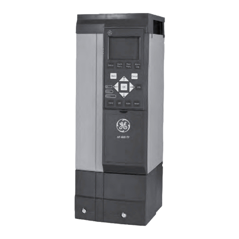
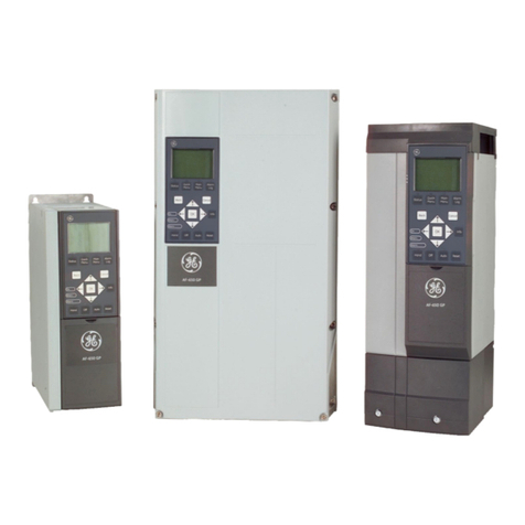
GE VAT20 User manual

GE Power Controls
AC SPEED CONTROL EQUIPMENT
VAT20
1ph 200V-240V System, 0.2-0.75kW
INSTRUCTION MANUAL
--------------------------------- NOTICE ------------------------------------------
1. Read this manual thoroughly before using the VAT20, and store
in a safe place for reference.
3. When using this inverter in the EU, compliance with the EMC Directive (89/336/EEC) is
required. Check carefully Chapter 2 -Wiring section in this manual.
4. The contents of this manual can be changed without notice
GE POWER CONTROLS

http://www.bzxindaxin.com http://www.gk-world.com
全球独家推出 全覆盖型省配线解决方案

http://www.bzxindaxin.com http://www.gk-world.com

http://www.bzxindaxin.com http://www.gk-world.com

http://www.bzxindaxin.com http://www.gk-world.com


II
Table of Contents
Foreword................................................................................... 1
Chapter 1 Safety Precautions
1. Precautions of operation........................................ 2
2. Precautions of operation environment ................... 4
Chapter 2 Hardware Instruction and Installation
1. Operation Environment.......................................... 5
2. Model No. Instructions........................................... 6
3. Specifications........................................................ 7
4. Wiring.................................................................... 8
5. Dimensions & terminal block layout......................14
Chapter 3 Software Index
1. Control Panel Instructions.....................................18
2. List of Parameters................................................19
3. Parameter Function Description ...........................20
4. Malfunction Indication and Countermeasure.........28
5. General Troubleshooting Method .........................31
Chapter 4 Maintenance and Peripherals

1
1. Foreword
To fully employ all functions of the inverter, and to ensure the safety of users, please read
through this operating manual in detail. Should you have any further query, please feel free to
contact your local distributor or sales person of GE Power Controls. Our professional staves
will be glad to serve whatever your need. Please continue your generous support and keep
adapting products from GE Power Controls.
Precaution
Inverter is a power electronic device, for safety reason, please take special care for
paragraphs with “WARNING” or “CAUTION” symbol. They are important safety precautions to
be aware of while transporting, installation, operating or examining the inverter. Please
following these precaution to ensure your safety.
WARNING Personnel injury may be resulted by improper operation.
CAUTION The inverter or mechanical s
y
stem ma
y
be dama
g
ed b
y
improper operation.
WARNING
Do not touch the PCB or components on the PCB right after turning off the power before the
charging indicator went off.
Do not attempt to wire circuitr
y
while power is on. Do not attempt to examine the
components and signals on the PCB while the inverter operating.
Do not attempt to disassemble or modif
y
internal circuitr
y
, wirin
g
, or components of the
inverter.
The grounding terminal of the inverter must be grounded properly with 200V class type III
standard.
CAUTION
Do not attempt to proceed dielectric stren
g
th test to internal components of the inverter.
There are sensitive semiconductor-devices vulnerable to high voltage in the inverter.
Do not connect the output terminals: T1(U), T2(V), and T3(W) to AC power outlet.
The CMOS IC on the primary PCB of the inverter is vulnerable to static electrical charges.
Do not contact the primary PCB of the inverter.
2. Examination before installation
Every GE Power Controls inverter has been fully tested and examined before shipment.
Please carry out following examination procedures after unpacking your inverter.
Check to see the model number of the inverter. It should be the one that you ordered.
Check to see if there is any damage during the transportation. Do not connect the inverter
to the power supply if there is any sign of damage.
Report to regional sale representative if you find any abnormal condition as mentioned above.
2
Chapter 1. Safety Precaution
1. Precautions of operation
Before turning ON power
CAUTION
Choose appropriate power source with correct volta
g
e settin
g
as the input volta
g
e
specification of the inverter.
WARNING
Special care must be taken while wirin
g
the primar
y
circuitr
y
panel. The L1 and L2
terminal must be connected to input power source and must not be mistakenl
y
connected to T1, T2 or T3 terminal. This may damage the inverter when the power is
turned on.
CAUTION
Do not attempt to transport the inverter by the front cover. Securely hold the inverter
b
y
the heat-sink mountin
g
chassis to prevent the inverter from fallin
g
that ma
y
cause personnel injury or damage the inverter.
Install the inverter onto firm metal base or other inflammable material. Do not install
the inverter onto or nearby any flammable material to avoid fire.
Additional coolin
g
fan should be installed if several inverter are installed into one
control panel to lower the temperature inside below 40•to avoid overheating or fire
alarm.
Turn off power supply before proceeding removal or installation of operating panel.
Carry out installation procedure according to instructions given to avoid poor-
contact situation resulting operating panel malfunction or no displaying information.
Suitable for use on a circuit capable of deliverin
g
not more than 5000RMS
symmetrical amperes.240V maximum
Not proved with over speed Protection or equivalent
Only intended for use in a pollution degree 2 macro environment or equivalent
When power turned ON
WARNING
Do not attempt to install or remove connector of inverter when the power suppl
y
is
turned on. Otherwise, the inverter may be damaged due to the surge peak caused by
the insertion or removal.

3
Under Operation
WARNING
Do not switch ON or OFF motor at the middle of operation. Otherwise, the inverter
over-current break-down may be resulted.
WARNING
Do not remove the front cover of the inverter when the power is ON to avoid
personnel injury caused by electrical shock.
When the automatic restart function is enabled, the motor machiner
y
will be
restarted automaticall
y
after full
y
stop from operation. Do not
g
et close to the
machinery to avoid personnel injury.
CAUTION
Do not touch the heat-sink base.
The inverter can be easil
y
operated from low-speed to hi
g
h-speed ran
g
e. Please
reconfirm the operating range of motor and machinery.
Do not examining the signals on the PCB of the inverter when it is under operation.
All inverter had been properly adjusted before delivery. Do not attempt to adjust it.
CAUTION
Do not proceed with disassemble or examination procedure before ensuring that the
power is off and the Power LED extinguished.
When examination and maintenance
CAUTION
Inverter environment should be within temp: –10OC ~ +40OC, humidity under 95% RH
without condensing.
CAUTION
After the removal of shield sticker, the environment temperature should be within –
10OC ~ +50OC and humidity under 95% RH without condensing. Besides, the inverter
should be free from water dripping or metal dust.

4
2. Precautions of operation environment
Avoid direct sunlight Away from corrosive gas
or liquid Away from oil grease
and gas
Away from salty
environment
Avoid where rain or
dripping water may get
into the inverter
Avoid metal dust and
dusty environment
Avoid massive vibration Avoid heat Avoid where environment
temperature is too high
Away from high electrical-
magnetic wave or ultra-high wave.
(such as electro-soldering
machine or other similar
machinery.)
Away from radio-active
matter Away from flammable
material
oil

5
Chapter 2. Hardware Instruction and Installation
1. Operation Environment
The installation site of the inverter pose direct impact to the fully functionality and the life-span
of your inverter. Please carefully choose the installation site to meet following requirements:
Mount the unit vertically
Environment temperature: -10OC ~ +40OC
without shield sticker : -10OC ~ +50OC
Avoid placing close to any heating equipment
Avoid water dripping or humid environment
Avoid direct sunlight
Avoid oil or salty corrosive gas
Avoid contacting corrosive liquid or gas
Prevent foreign dusts, flocks, or metal scraps from entering interior
Away from radioactive matter or flammable material
Avoid electric-magnetic interference (soldering or power machinery)
Avoid vibration, if vibration can not be avoided, anti-rattler should be installed to reduce it.
If inverter is installed in control panel, please tear off shield sticker of VAT20.Additional
cooling fan should be installed to lower the environment below 50OC
Installation of the inverter must place the front side of inverter facing front and the top of
inverter towards up direction for better heat dissipation.
Installation rooming must be compliant to following requirement.
NOTE: Please tear off shield sticker of VAT20 for max temperature iside the enclosure of 50ºC

6
2. Model No. Instructions
Inverter Model ➟MODEL: U20N0K7S (for example)
Input Power Rating➟I/P: AC 1PH 200 ~ 240V 50/60 Hz
Output Rating ➟O/P: AC 3PH 0 ~ 240V 1.6KVA 4.2A
U20 -N0K7
-
S
Series Power
Voltage KW Power
Rated Option
N:200V 0K2: 0.2kW S: Standard
Single 0K4: 0.4kW model
Phase 0K7: 0.7kW
I K5: 1.5kW
2K2: 2.2kW

7
3
Specifications
Model No: VAT20- U20N0K2S U20N0K4S U20N0K7S U20N1K5S U20N2K2S
Suitable Motor Power Rating (KW) 0.2 0.4 0.75 1.5 2.2
Motor HP 1/4 1/2 1 2 3
Current A 1.4 2.3 4.2 7.5 10.5
Capacity KVA 0.53 0.88 1.6 2.9 4.0
Rated
Weight (Kg ) 0.76 0.77 0.8 1.5 1.6
Input Voltage Max. Single phase 200-240V (+10%-15%) , 50/60Hz (+/-5%)
Output Voltage Max. Three phase 200-240V +10%-15% (Input Voltage Max)
Input Signal Type PNP type (SOURCE) input
Control Method Sinusoidal wave PWM control
Freq. Range 0~120 Hz
Resolution Setting Digital : 0.1 Hz(0~99.9Hz); 1Hz(100~120Hz)
Analog:0.06Hz/60Hz
Keyboard Setting Directly setup by
buttons.
External Signal Setting 0~10V, 4~20mA , 0~20mA
Freq.
Control
Other function Frequency upper and lower limit
Accelerate/Decelerate time 0.1~ 999 Sec
V/F Pattern 6 Patterns
Torque control Torque boost level adjustable (manual torque boost)
Multi-Function input 2 point, to be used as multi-speed 1
(
Sp1
)
/ Jo
g
/ External
emergency stop / External bb / Reset
Multi-Function output 1a Relay terminal, to be setup as Fault / Running / Frequency.
Braking Torque About 20%, additional breaking resistance not allowed
General
Control
Other function Decelerate or free run stop, Auto reset, DC braking frequency
/ Voltage / Time can be setup by constants.
Indication function 7 se
g
ments*3 indicate fre
q
uenc
y
/ inverter parameter / fault
record / program version.
Operating temperature -10 ~ 40OC
Humidity 0~95% RH non-condensing.
Vibration Under 1 G ( 9.8 m/s2)
EMC specification Class A ( Filter build in )
Protection level IP20
UL UL508C
Overload protection 150% for 1min.
Over-voltage DC voltage > 410V
Under voltage DC voltage < 200V
Momentary power-loss 0 ~ 2 sec : VAT20 can be restart by speed search
Protection
function
Stall Prevention Accelerate / Decelerate / Constant speed
Output terminal short-circuit Electronic circuitry protection
Grounding fault Electronic Circuitry protection
Protection
function Other function Heat sink protection , Current limit
Dimension(W*H*D) mm 72*132*118 115*140*145
Installation Install by mounting screw or DIN rail (Option).

8
3. Wiring
Molded-Case Circuit Breaker / Magnetic Contact
GE Power Controls maintenance and service do not apply to damage caused by
following situation:
(1) Damage to the inverter caused by the lack of appropriate molded-case circuit breaker
or a circuit breaker with too-large capacity is installed in between the power supply and
the inverter.
(2) Damage to the inverter caused by the serial magnetic contactor, phase advancing
capacitor, or surge-protector in between the inverter and the motor.
Model No: U20N 0K2S 0K4S 0K7S 1K5S 2K2S
Molded-case circuit breaker line
Made by GE 20A 30A 30A
Magnetic Contact
(MC)
Made by GE
CL00
Made by GE
CL00
Made by GE
CL00
Primary Circuit Terminal (TM1) Wire dimension
2.5mm2
Terminal screw M3
Wire dimension
2.5mm2
Terminal screw M3
Wire dimension
2.5mm2
Terminal screw M3
Signal Terminal (TM2)
1~11
Wire dimension 0.75mm2(#18 AWG), Terminal screw M3
Please utilize three-phase squirrel-cage induction motor with appropriate capacity.
If a inverter is used to drive more than one motor, the total capacity must be smaller
than the capacity of the inverter. Additional thermal relay must be installed in front of
every motor. Use the Fn_18 at 1.0 times of the rated value specified on the motor
nameplate at 50Hz, 1.1 times of the rated value specified on the motor nameplate at
60Hz.
Do not install phase advancing capacitor, LC, or RC component between the inverter
and the motor.
T3
T1 T2
L1 L2

9
Application and precautions of Peripherals
Power Source
Ensure to appl
y
power source at correct rated volta
g
e to prevent
form damaging the inverter.
Circuit breaker must be installed in between the AC power
supply and the inverter.
Molded-case circuit breaker:
Utilize appropriate circuit breaker suitable for the rated volta
g
e
and current ratin
g
s of the inverter to switch ON/OFF the power
supply to the inverter and as a protection for the inverter.
Do not operate the circuit breaker to switch ON or OFF the
inverter.
Leakage circuit breaker:
Leaka
g
e circuit breaker should be added to prevent false
operation cause b
y
leaka
g
e current and to ensure personnel
safety.
Magnetic Contact:
The Ma
g
netic Contact can be omitted at ordinar
y
operation. To
utilize external control, automatic restart, or breakin
g
controller
the magnetic contact must be added at the primary side.
Do not operate the ma
g
netic contact to switch ON or OFF the
inverter.
Power improvement AC Reactor:
If lar
g
e capacit
y
power source is applied (over 600KVA),
additional AC reactor may be added to improve power factor.
Inverter:
Power suppl
y
input terminals L1 and L2 is not differentiated
on phase se
q
uence, the
y
can be arbitraril
y
connected. Their
connection may be exchanged.
Output terminal T1, T2, and T3 should be connected to the U, V,
and W terminals of the motor respectivel
y
. If motor turns in
opposite direction of the inverter, simpl
y
exchan
g
in
g
two of three
wire connection may correct this problem.
Output terminal T1, T2, and T3 must not be connected to power
source to prevent from damaging inverter.
Groundin
g
terminal Properl
y
g
round the
g
roundin
g
terminal in
compliance to 200V class type three grounding
Power supply
Molded-case
circuit breaker
or ground fault
interrupter
Electrical-
Mangnetic
contactor
AC reactor
for power
factor improve-
ment
Grounding
VAT20
Inverter
Motor
Grounding

10
External wiring should be carried out in accordance with following requirement. Check and
reassure the wiring is correct after the wiring is complete. (Do not utilize the control circuitry buzzer
to check the wiring.)
EMI connecting:
It is very important that the connections between the frequency inverter with the screened motor
cable and the EMI filter during the EMI tests are as following.
Use a metal grounding plate and place the frequency inverter and the EMI filter on the plate.
Use a screened motor cable with 4 connectors ( U,V,W,& Earth ), don’t use the shielding as
safety earth ( shield is high frequency earth )
Remove painting around the two metal coupling nut holes. So that the metal coupling nuts (
and the shielding ) make contact with the frequency inverter and the motor.
Don't solder a conductor to the shielding ( pig tail )
Use a metal clamp to connect the shielding from the motor cable with the metal grounding
plate. Now there is a perfect high frequency earth connection between frequency inverter .
grounding plate and EMI filter.
Keep the distance between frequency inverter and EMI filter as short as possible ( < 30cm )
otherwise use screened cable with a metal coupling nut and a metal clamp addle to connect
the shielded cable to the frequency inverter and metal grounding plate.
The only earth connection between the LISN and the test plate should be via the EMI filter.
Use a motor which belongs to the power rate of the frequency inverter . otherwise use a
motor of less power.
Install a noise filter for inverter onto the output side of the primary circuitry can suppress
conducting noise. To reduce radio active noise, a metal pipe should be apply for wiring, and
the wiring should be away from other controlling machine for more than 30 cm.
Class B (Residential Environment)

11
Class A, Industrial Environment
When the distance between the inverter and motor is longer than 100m, connection wire
should be carefully chosen to reduce the wiring resistance below 3% and the voltage drop
(V) =
3 x Wire resistance (Ω/km) x wire length (m) x current x 10-3
(B) Control circuitry wiring must be separated and away from the primary circuitry control line and
other high-voltage or large-current power lines to avoid noise interference.
To reduce the noise interference and avoid mistake operation, shielded twisted pair cable
must be used to wire the control circuitry. Please refer to following diagram. Connect the
shielding wire onto the grounding terminal.
Wiring distance must be under 50m.
(C) The grounding terminal of the inverter must be correctly grounded in compliance with 200V
class type three grounding.
Grounding wire should be wired in accordance to electrical equipment (AWG) with the
length of the grounding wire as short as possible.
The grounding wire of the inverter must not be grounded together with other large current
loading (such as soldering machine or large power motor). They should be grounded
separately.
Grounding circuitry must not be formed when grounding several inverters together.
Shielding Glove
To Inverter terminal
Connect to system grounding terminal
Wrapped with
insulating tape
To control machine
Do not connect the shielding
wire at this end

12
(a)good (b) good (c) not good
(D) Wire specification Choose appropriate wire with correct diameter for primary power circuitry
and control circuitry in accordance with electricity regulations.
(E) Upon completion, check out to reassure the wiring correctness, broken wires, and secure
terminal screws. VAT20 Wiring Diagram
Terminations to Inverter must be made with either listed field wiring lug kits or listed crimp
type ring terminals
Other connections(external 24V supply)
Ω

13
VAT20 series inverter terminal descriptions
Primary circuitry terminal black ( TM1 ) descriptions
Terminal symbol Function description
L1 (R)
L2 (S)
Primary power source input
T1 (U)
T2 (V)
T3 (W)
Inverter output
* Tightening torque for TM1 is 0.98 Nm.
* Use copper conductors only size field wiring based on 75 degrees C wire only.
* Wire voltage rating must be a minimum of 300V
* Electric ratings of the termination (TM1) as 300V 15A
VAT20 control circuitry terminal block ( TM2 ) description
Terminal symbol Terminal function description
1
2
TRIP
RELAY
Fault relay output terminal
Connection point rated capacity 250VAC/1A ( 30VDC / 1A )
3FWD
4REV
Operation control terminals (refer to Fn_03)
5 + 12V Common point of terminal 3 / 4 / 6 / 7
6 SP1
7 RESET
Multifunction input terminals (refer to Fn_19)
8 +10V Power terminal of potentiometer ( Pin 3 )
9 Analog input point Analog frequency signal input terminal ( Pin 2 of
potentiometer or positive terminal of 0~10V / 4~20mA
/ 0~20mA)
10 0V
(FM -) Analog common point Analog signal common point ( Pin 1 of potentiometer
or negative terminal of 0~10V / 4~20mA / 0~20mA )
11 FM+ Analog output positive
connection point Analog frequency signal output terminal
Output terminal signal is 0 ~ 10VDC/Fn6
* Tightening torque for TM2 is 0.4 Nm.
* Use copper conductors only size field wiring based on 75 degrees C wire only.
* Wire voltage rating must be a minimum of 300V
* Control wiring should not run in the same conduit or race way with power or motor wiring
* Single Input and Output Terminals (TM2) Ratings are ALL Class 2
Other manuals for VAT20
2
Table of contents
Other GE Controllers manuals