4 9
HOB USE
USING GAS BURNERS
The following symbols are on the control panel next to each knob:
- Black circle gas off
- Large flame maximum setting
- Small flame minimum setting
The minimum setting is at the end of the anticlockwise rotation of
the knob. All operation positions must be selected between the
positions of max. and min., never select them between max.and
off.
MANUAL IGNITION
To ignite the burner, press the knob of the selected burner and
turn it anticlockwise to the minimum position then light with a
match.
ELECTRIC IGNITION (optional)
To ignite the burner, press the knob of the selected burner and
turn it anticlockwise to the minimum position;simultaneously press
the electric ignition button on the control panel marked with symbol
.In the case of a power failure, the burner can be lit using a
match.
AUTOMATIC ELECTRIC IGNITION (optional)
To ignite the burner, press the knob of the selected burner and
turn it anticlockwise to the minimum position. Keeping the knob
pressed in, the automatic ignition of the burner will operate.
In case of power failure, the burner can also be lit using a match.
APPLIANCESWITH SAFETY VALVE (optional)
Follow the same procedure described above to ignite the burners.
In this case, once the burner is lit you have to hold the control
knob pressed in for approximately 10 seconds until the burner
flame stays on, if the flame does not stay on repeat the process.
If for any reason the burner flame goes out, the safety valve
automatically shuts off the gas supply to the burner in question.
ENERGY SAVING TIPS
•The diameter of the pan bottom should correspond to that of
the burner.The burner flame must never extend beyond the
diameter of the pan. Use flat-bottomed pans only.
•Whenever possible, keep a lid on the pan while cooking, this
will save energy.
•Cook vegetables, potatoes, etc.with as little water as possible
to reduce cooking times.
Fig.1
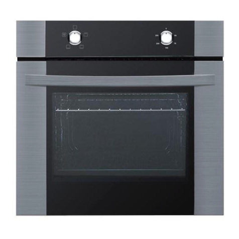
USE OFTHE ELECTRIC OVEN
The first time the oven is used, it may give off smells, these are
caused by residues left by the production processes and is quite
normal (it is necessary to heat up the oven at the maximum
temperature for about 30-40 minutes in order to burn off these
residues).
Once this process is complete cooking can commence.
The oven is fitted with:a wire trivet for cooking food contained in
oven dishes or placed directly on the trivet itself, a drip-tray for
cooking sweets, biscuits, pizzas, etc., or for collecting juices and
fats from food cooked directly on the trivet.
Note: The following tables give the main points for cooking some
of the most common dishes.The cooking times recommended in
these tables are approximate. After a few tries, we are sure that
you will be able to adjust the times to get the results you want.
Conventional cooking tableTAB. B
Fan oven cooking table TAB.C.
GAS CONNECTION
The cooker is fitted with 4 legs that can be andjusted in height
with the furniture.To assemble them, it is necessary to raise the
cooker and to screw the four legs into the position situsted on the
corners of the bottom of the appliance fig.13.
Dish Temp. °C. Minutes Weight kg.
Firs courses
Lasagne 200-220 20-25 0,5
Oven pasta 200-220 25-30 0,5
Creole rice 200-230 20-25 0,5
Pizza 210-230 30-45 0,5
Meat
Roast veal 160-180 65-90 1-1,2
Roast pork 160-170 70-100 1-1,2
Roast ox 170-190 40-60 1-1,2
Roast beef joint 170-180 65-90 1-1,2
Roast fillet beef (rare) 180-190 40-45 1-1,5
Roast lamb 140-160 100-130 1,5
Roast chicken 180 70-90 1-1,2
Roast duck 170-180 100-160 1,5-2
Roast goose 160-180 120-160 3-3,5
Roast turkey 160-170 160-240 5 approx.
Roast rabbit 160-170 80-100 2 approx.
Roast hare 170-180 30-50 2 approx.
Fish 160-180 acc. to weight
Sweets (pastries)
Fruit flan 180-200 40-50
Plain sandwich cake 160-180 35-45
Sponge sandwich cake 200-220 40-45
Sponge cake 200-230 25-35
Currant cake 230-250 30-40
Buns 170-180 40-60
Strûdel 160 25-35
Cream slices 180-200 20-30
Apple fritters 180-200 18-25
Sponge finger pudding 170-180 30-40
Sponge finder biscuits 150-180 50-60
Toasted sandwiches 230-250 7
Bread 200-220 40
Dish Temp. °C. Minutes
Fish 180-240 acc. to size
Meat
Roast ox 250 30 per kg.
Roast veal 200-220 30 per kg.
Chicken 200-240 50 about
Duck and goose 220 acc.to weight
Leg of mutton 250 30 per kg.
Roast pork 250 60 per kg.
Soufflets 200 60 per kg.
Sweets (pastries)
Tea-cake 160 50-60
Sponge finger 160 30-50
Shortcrust pastry 200 15
Puff pastry 250 15
Fruit flan 200-220 30
Meringues 100 60
Quiches, etc. 220 30
4 quarters 120-140 60
Buns 160-180 45
This appliance shall be installed in accordance whit the regulations
in force and only in a well-ventilated space.Read the instructions
before installing or using this appliance.
IMPORTANT
This cooker is supplied for use on Natural Gas Only and cannot
be used for any other gas without modification.
Conversion for use on LPG and other gases must only be
undertaken by a qualified person.For information for use on other
gases contact your local Service Centre.
The cooker must be installed by a qualified person in accordance
with the current edition of the Gas Safety (Installation and Use)
(Amendment) Regulations and the relevant building/I.E.E.
Regulations.
Failure to install the appliance correctly could invalidate any
manufacturers warranty and lead to prosecution under the above
quoted regulations.
In the UK, CORGI registered installers are authorised to undertake
the installation and service work in compliance with the above
regulations.All Baumatic engineers are CORGI registered.
Provision forVentilation
The room containing the cooker should have an air supply in
accordance with the current edition of BS 5440: Part 2:The room
must have an opening windows or equivalent; some rooms may
also require a permanent vent.If the room has a volume between
5 and 10m3, it will require an air vent of 50cm2 effective area unless
it has a door which opens directly to the outside. If the room has
a volume of less than 5m3, it will require an air vent of 100cm2
effective area. If there are other fuel burning appliances in the
same room the current edition of BS 5440: Part 2: should be
consulted to determine air vent requirements. Ensure that the
room containing the cooker is well ventilated, keep natural ventilation
holes or install a mechanical ventilation device (mechanical cooker
hood). Prolonged intensive use of the appliance may call for
additional ventilation, for example opening of a window, or more
effective ventilation, for example increasing the level of mechanical
ventilation where present. This cooker is not fitted with a device
for discharging the products of combustion. Ensure that the
ventilation rules and regulations are followed. Excess steam from
the oven, vents out at the top back edge of the cooker, so make
sure that the walls behind and near the cooker are resistant to
heat, steam and condensation. Your cooker must stand on a flat
surface so that when it is in position the hob is level. When in
position check that the cooker is level by using a spirit level and
adjust the 2 feet at the rear and the 2 feet at the front if necessary.
It is important that the cooker is stable and level for the overall
cooking performance.
Remember that the quantity of air necessary for combustion must
BURNERS PANS
Ø min. Ø max
RAPIDE 180 mm 220 mm
SEMIRAPIDE 120 mm 200 mm
AUXILIARY 80 mm 160 mm
TRIPLE CROWN 220 mm 260 mm
never be less than 2m3/h for each kW of power (see total power
in kW on the appliance data plate).
Gas Safety (Installation & Use) Regulations
It is the law that all gas appliances are installed by competent
persons in accordance with the current edition of the Installation
& Use Regulations. It is in your interest and that of safety to
ensure compliance with the law.
In the UK, CORGI registered installers work to safe standards of
practice. The cooker must also be installed in accordance with the
current edition of BS 6172. Failure to install the cooker correctly
could invalidate the warranty, liability claims and could lead to
prosecution.
Gas Connection (all installation and service work must be
carried by a CORGI registered engineer)
Prior to installation, ensure that the gas suppli conditions (nature
of the gas and gas pressure) and the adjustment conditions are
compatible.The adjustment conditions for this appliance are stated
on the rating plate which can be found on the back cover.
This appliance is not designed to be connected to a combustion
products evacuation device.Particular attention should be given
to the relevant requirements regarding ventilation.
Connection to the cooker should be made with an approved
appliance flexible connection to BS 669.Models for use with LPG
should be fitted with a hose suitable for LPG and capable of
withstanding 50mbar pressure. A length of 0.9 to 1.25m is
recommended. The length of hose chosen should be such that
when the cooker is in situ, the hose does not touch the floor.
The temperature rise of areas at the rear of the cooker that are
likely to come in contact with the flexible hose do not exceed 700C.
Gas pressure may be checked on a semi-rapid hob burner.Remove
the appropriate injector and attach a test nipple. Light the other
burners and observe that the gas pressure complies with the gas
standards in force.
Certain types of cookers can be connected to the supply both on
the right and left hand side at the rear of the cooker.To reverse
the position, remove the blanking plug and refit in the side not to
be used. On completion carry out a gas soundness.
Fig. 14
ELECTRICAL CONNECTION
This appliance must be installed by a qualified person in
accordance with the latest edition of the IEE Regulations and
in compliance with the manufacturer instructions.
Ensure that the voltage is the same as that stated on the rating
plate.The rating plate can be found on the back cover .
WARNING!THIS APPLIANCE MUST BE EARTHED
The cooker must be connected to a suitable cooker control unit
incorporating a double pole switch having a contact separation
of at least 3mm in all poles, which is adjacent to (but not above),
and not more than1.25m away from the cooker and easily
accessible. We recommend that the cooker circuit is rated to
20amps.
Cable type H05 RRF 3X 2.5mm2
Connecting the mains cable
Open the mains terminal block cover as shown, unscrew the cable
clamp «A» and unscrew (not fully) the screws in the mains terminal
block «L N E» which secure the three wires of the mains cable.
Fit the cable and refit the cable clamp «A» .
Allow sufficient cable length for the cooker to be pulled out for
Fig. 12
INLET STOP
