Designed by Matthew Weatherly.
ThesedistinctiveproductcongurationsareprotectedbyUSandinternationalpatents,tradedress,and/or
copyright laws. Sola & BDI are trademarks of Becker Designed, Inc. All rights reserved. ©2018, BDI
Patent: www.bdiusa.com/ip
Made in China. 06.14.2018 V1
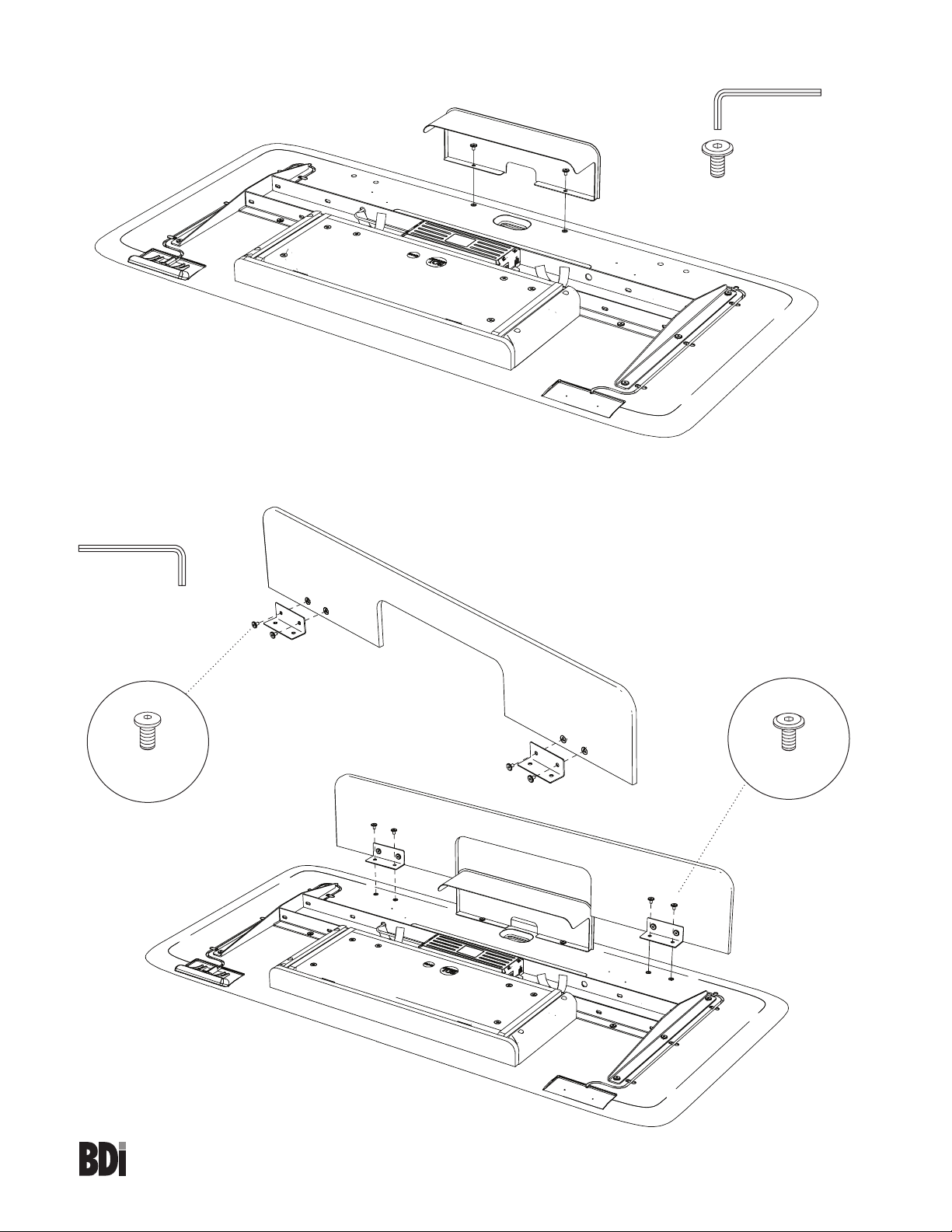
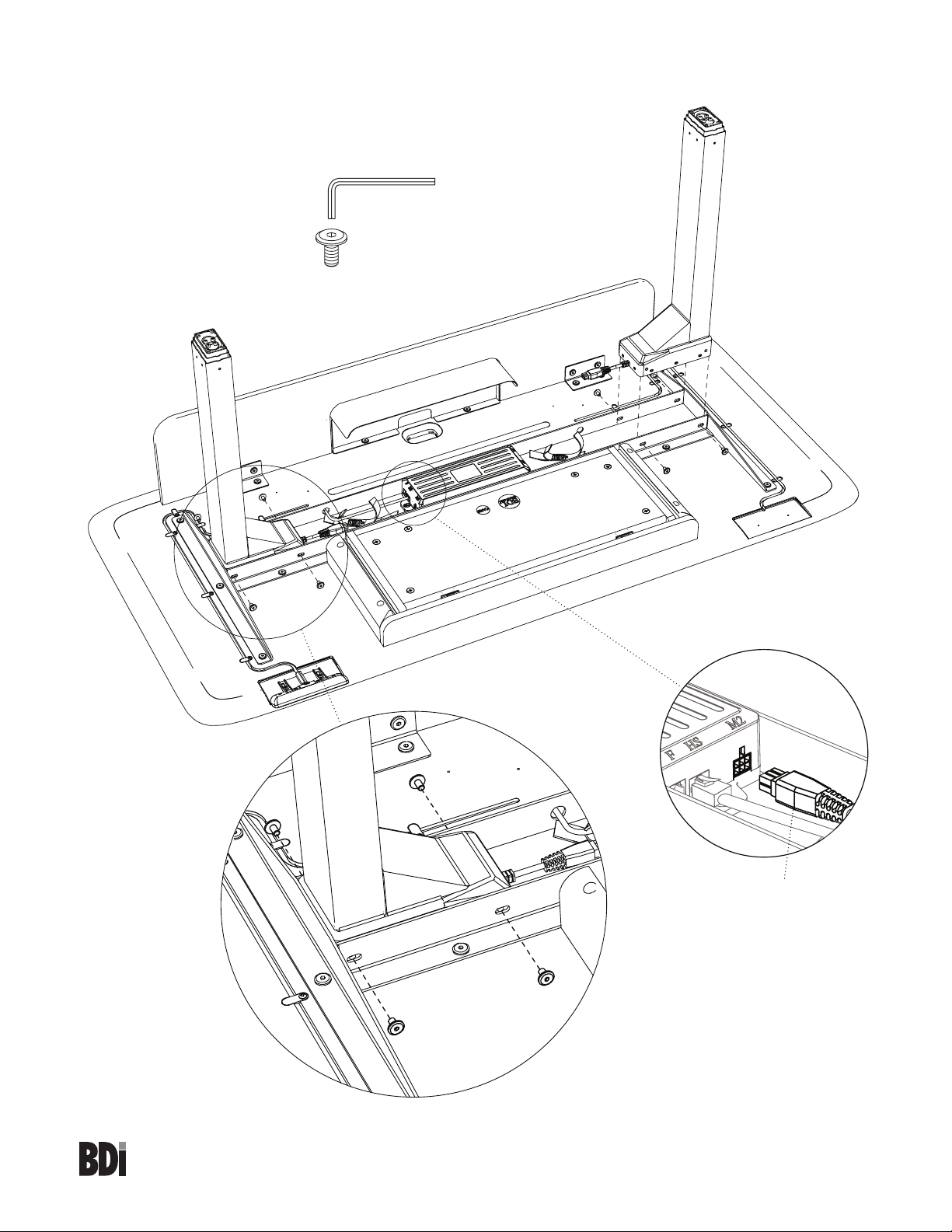
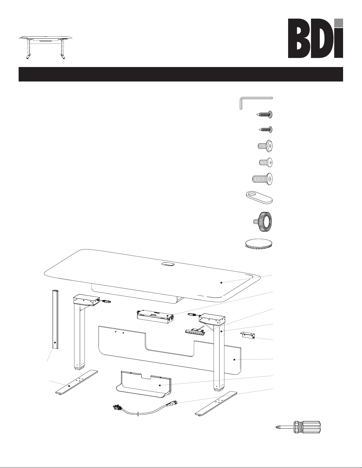
T1 4mm Hex Wrench
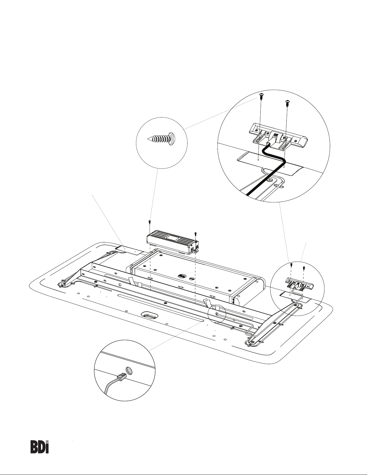
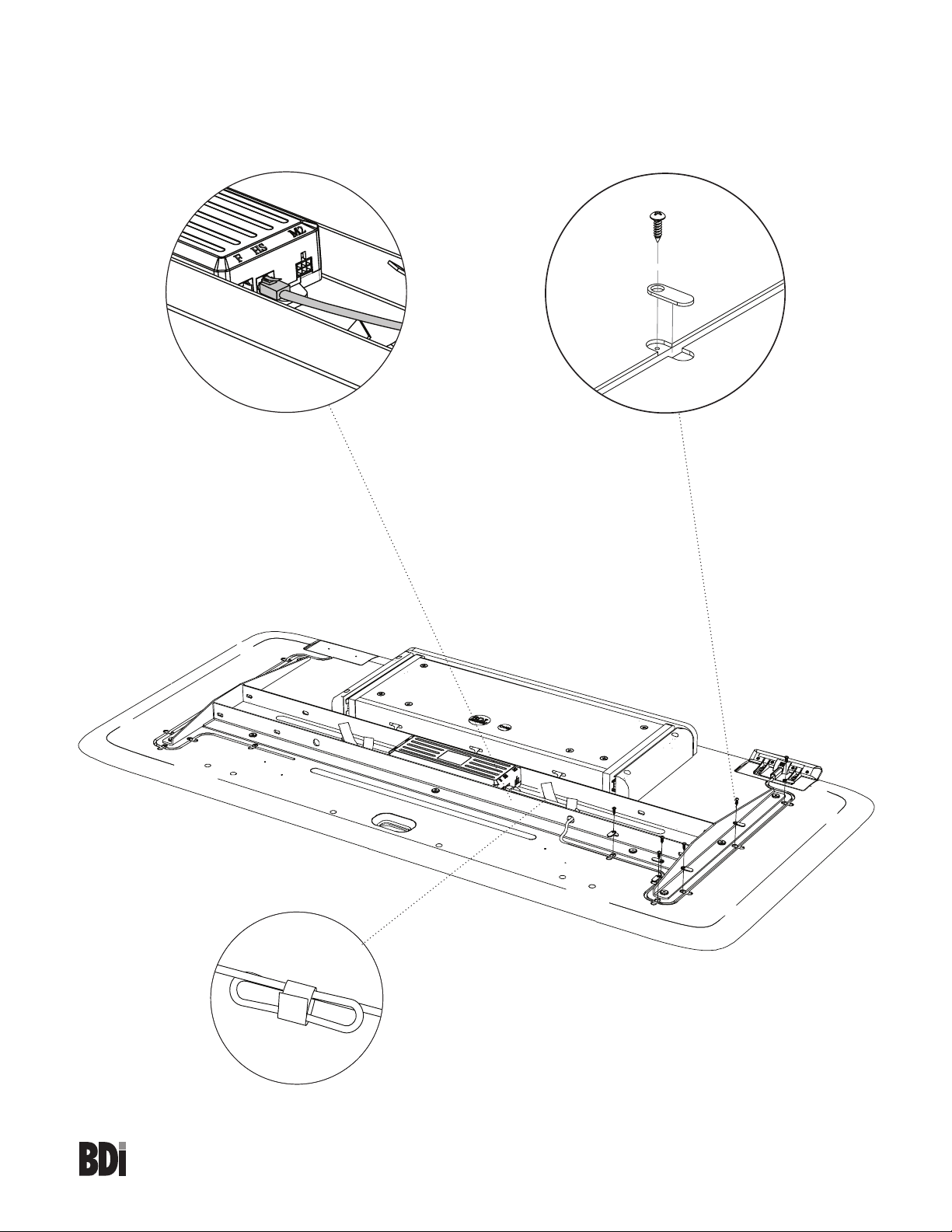
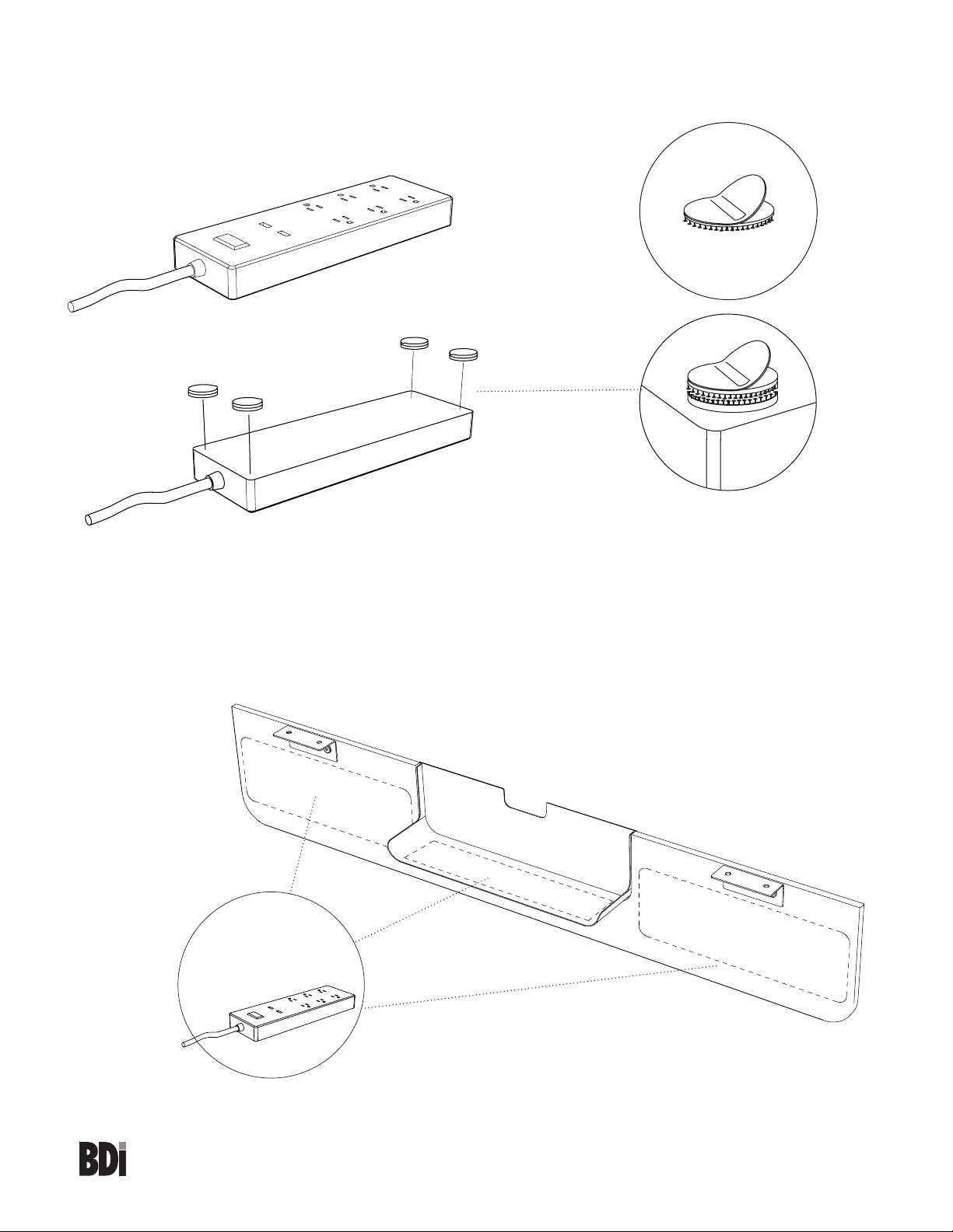
C7 Wire tray x 1
C9 Modesty panel x 1
C8 Modesty panel
bracket x 2
C4 Keypad x 1
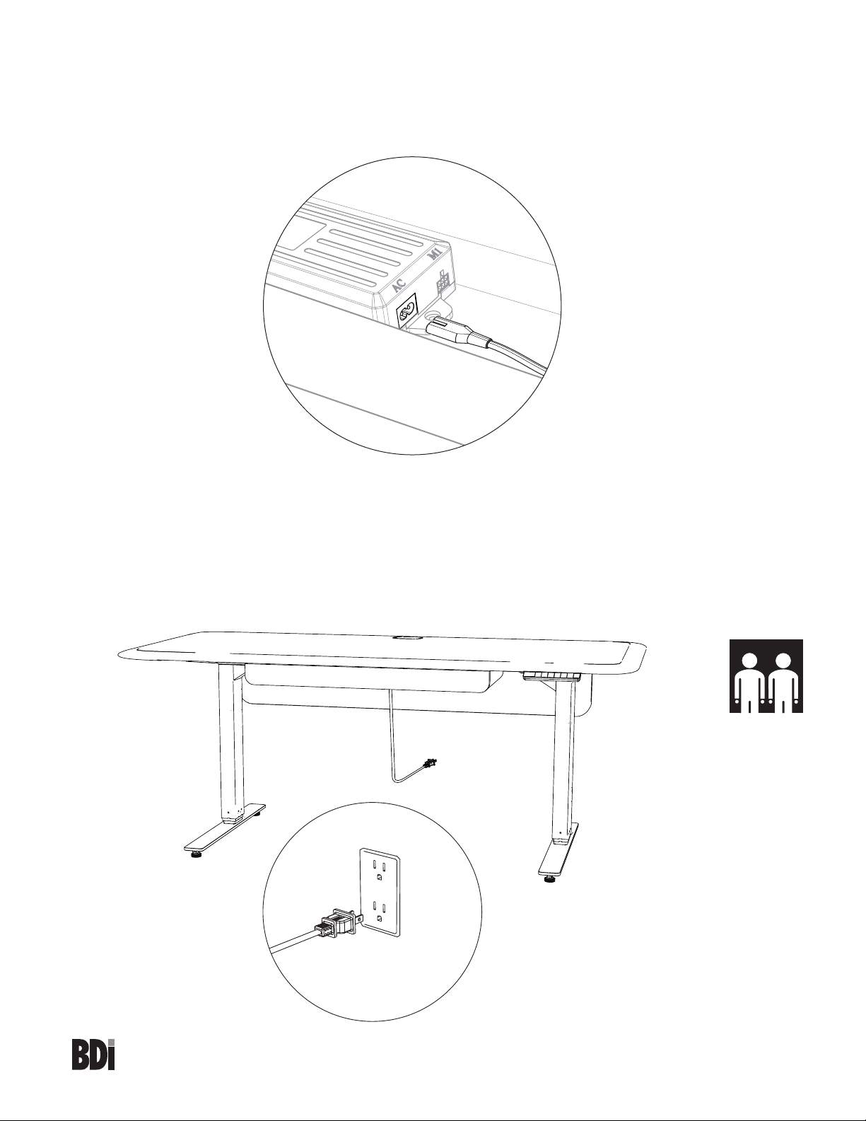
C5 Power Cord x 1
C3 Control Module x 1
A1 Main Panel x 1
C1 Leg x 2
C6 Cord
Conduit x 1
C2 Foot x 2
bdiusa.com
customerservice@bdiusa.com
SOLA®6853
LIFT DESK
Tool Required:
Phillips screwdriver
Tool Included:
H2 #6 Wood Screw x 6
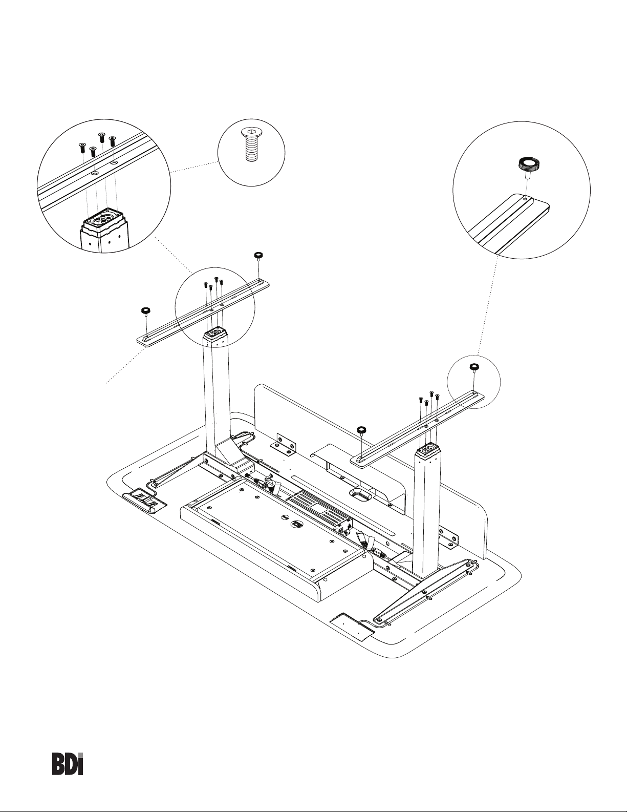
H3 M6 x 11mm Screw x 14
H4 M6 x 9mm Screw x 4
H9 Dual Lock Dot x 8
Product Registration
Registering your new BDI product allows us to send you important
product updates, service information and helpful hints related to your BDI
products. Register today, and you will be entered to win free a BINK table
from BDI: www.bdiusa.com/register
Placement and Maintenance
Sola®Lift Desk is designed for indoor use on level floors. Clean steel
parts and wood panel with a moist cloth.
Your Sola®Office furniture is engineered for easy assembly. Carefully
follow this procedure to prevent any damage. Do not use power tools
for assembly of this product.
Step 1
Unpack and identify the parts listed below. The assembly workspace
should be a non-marring surface such as carpet. For missing hardware
pieces, please contact BDI Customer Service at
For all other concerns, please contact your BDI retailer.
H7 Leveler x 4
H1 #10 Wood Screw x 4
H5 M6 x 16mm Screw x 8
H6 Wire clip x 6
OWNER’S MANUAL