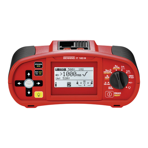
BENNING IT 130 Content
- 4 -
5.5
Loop impedance and prospective short-circuit current...............................................46
5.6
Line impedance and prospective short-circuit current / voltage drop....................48
5.6.1
Line impedance and prospective short-circuit current ........................................49
5.6.2
Voltage drop......................................................................................................50
5.7
Earthing resistance ...................................................................................................52
5.8
Testing the protective conductor connection (PE) .....................................................54
5.9
TRMS current by means of current clamp adapter ....................................................56
5.10
Single-fault leakage current (ISFL) in IT networks .....................................................57
5.11
Luminous intensity ....................................................................................................59
6
Management of measured values..................................................................................61
6.1
Memory structure ......................................................................................................61
6.2
Saving measuring results ..........................................................................................63
6.3
Recalling measuring results ......................................................................................64
6.4
Deleting measuring results........................................................................................65
6.4.1
Deleting the entire measured value memory......................................................65
6.4.2
Deleting all measurements of each storage location and subordinate storage
locations 65
6.4.3
Deleting an individual measurement..................................................................66
6.5
Renaming installation structure fields ........................................................................67
6.5.1
Renaming installation structure fields by means of the PC software ..................67
6.5.2
Renaming the installation structure fields by means of the barcode scanner .....67
6.6
USB and RS232 interface .........................................................................................68
7
Maintenance ....................................................................................................................69
7.1
Fuse replacement .....................................................................................................69
7.2
Cleaning....................................................................................................................69
7.3
Periodic calibration....................................................................................................69
7.4
Service......................................................................................................................70
8
Technical data.................................................................................................................71
8.1
Insulating resistance..................................................................................................71
8.2
Low-impedance resistance / continuity test ...............................................................72
8.2.1
Low-impedance resistance R LOW ...................................................................72
8.2.2
Continuity test....................................................................................................72
8.3
Residual current protection devices (RCDs)..............................................................72
8.3.1
General data......................................................................................................72
8.3.2
Contact voltage (Uc)..........................................................................................73
8.3.3
Tripping time (RCD t).........................................................................................73
8.3.4
Tripping current (RCD I) ....................................................................................74
8.4
Loop impedance and prospective short-circuit current...............................................75
8.4.1
Zs function (for systems without RCD)...............................................................75
8.4.2
Zsrcd function (for systems with RCD)...............................................................75
8.5
Line impedance and prospective short-circuit current / voltage drop .........................76
8.6
Earthing resistance ...................................................................................................77
8.7
TRMS voltage, frequency and phase sequence ........................................................77
8.7.1
TRMS voltage (AC/DC) .....................................................................................77
8.7.2
Voltage of the connection monitor .....................................................................77
8.7.3
Frequency .........................................................................................................77
8.7.4
Phase sequence (rotary field)............................................................................77
8.8
TRMS current (AC / DC) via current clamp adapter...................................................78
8.9
Single-fault leakage current (ISFL) in IT networks .....................................................79
8.10
Luminous intensity ....................................................................................................79
8.11
General data .............................................................................................................80


