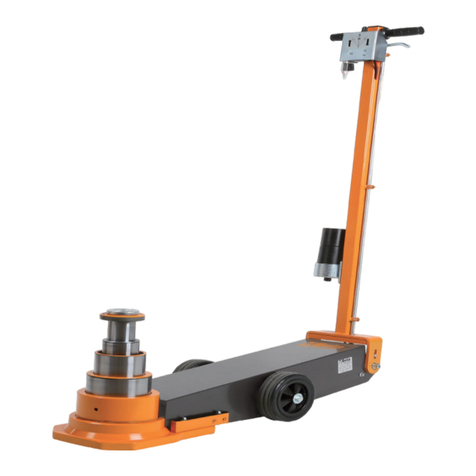
Beta 3067/60-15T User manual

ISTRUZIONI PER L’USOIT
INSTRUCTIONS FOR USEEN
MODE D’EMPLOIFR
GEBRAUCHSANWEISUNGDE
INSTRUCCIONESES
INSTRUÇÕES DE USOPT
GEBRUIKSAANWIJZINGNL
INSTRUKCJA OBSŁUGIPL
HASZNÁLATI ÚTMUTATÓ
HU
3067/60-15T
3067.60-15T.indd 1 13/04/18 15:30

2
ISTRUZIONI PER L’USO IT
SOLLEVATORE OLEOPNEUMATICO
MANUALE D’USO ED ISTRUZIONI PER SOLLEVATORE OLEOPNEUMATICO PRODOTTA DA:
BETA UTENSILI S.P.A. Via A. Volta 18, 20845, Sovico (MB) ITALIA
Documentazione redatta originariamente in lingua ITALIANA.
Conservare accuratamente le istruzioni di sicurezza e consegnarle al personale utilizzatore.
DESTINAZIONE D’USO
Il sollevatore oleodinamico è destinato al seguente uso:
• Indicato per il sollevamento di mezzi di trasporto
Non sono consentite le seguenti operazioni:
• è vietato l’impiego del sollevatore oleodinamico come sostegno
• è vietato lavorare ed operare sotto al mezzo che si sta sollevando
• è vietato l’uso per il sollevamento e/o lo spostamento di persone
• è vietato l’uso per tutte quelle applicazioni diverse da quelle indicate
• è vietato superare il carico massimo indicato in tabella DATI TECNICI
SICUREZZA DELLA POSTAZIONE DI LAVORO
Per garantire la sicurezza durante l’impiego del sollevatore idraulico, l’utilizzo è consentito
ad una sola persona.
Impedire che bambini o visitatori possano avvicinarsi alla postazione di lavoro mentre si sta
operando con il sollevatore. La presenza di altre persone provoca distrazione e può comportare
la perdita del controllo durante l’utilizzo.
Utilizzare il sollevatore su un pavimento con supercie piana. Non sollevare mai carichi su terreni
in pendenza.
L’utilizzo del sollevatore su pavimenti sconnessi e cedevoli può comportare instabilità del carico.
Non sollevare il carico in spazi ristretti per non correre il rischio di intrappolamento.
Non utilizzare più sollevatori contemporaneamente sullo stesso carico.
Non posizionarsi mai sotto il carico no a quando lo stesso non sia stato collocato su appositi
cavalletti di sostegno.
Prima di procedere ad una operazione di sollevamento, occorre bloccare il veicolo con il freno
di stazionamento e/o ponendo due cunei in corrispondenza delle ruote.
Se il veicolo è carico, prima di iniziare il sollevamento vericare la stabilità del carico.
Durante l’utilizzo del sollevatore, il motore del veicolo deve essere mantenuto sempre spento.
MPORTANTE LEGGERE COMPLETAMENTE IL PRESENTE MANUALE
PRIMA DI UTILIZZARE IL SOLLEVATORE OLEOPNEUMATICO. IN CASO DI
MANCATO RISPETTO DELLE NORME DI SICUREZZA E DELLE
ISTRUZIONI OPERATIVE, POSSONO VERIFICARSI SERI INFORTUNI.
ATTENZIONE
3067.60-15T.indd 2 13/04/18 15:30

3
ISTRUZIONI PER L’USO IT
INDICAZIONE PER LA SICUREZZA DEL PERSONALE
• Si raccomanda la massima attenzione, avendo cura di concentrarsi sempre sulle proprie azioni. Non
utilizzare il sollevatore in caso di stanchezza o sotto l’effetto di droghe, bevande alcoliche o medicinali.
• PRESTARE SEMPRE LA MASSIMA ATTENZIONE DURANTE LE ATTIVITÀ PREVISTE PER
L’UTILIZZO DEL SOLLEVATORE AL FINE DI EVITARE POSSIBILI SERI INFORTUNI.
• Utilizzare sempre i seguenti dispositivi individuale di protezione:
• Scarpe di sicurezza;
• Guanti di protezione con adeguata resistenza meccanica
• Avere cura di eseguire le operazioni di utilizzo del sollevatore in posizione sicura mantenendo il proprio
l’equilibrio in ogni momento. Una posizione di lavoro sicura ed un’adatta postura del corpo permettono
di poter controllare meglio eventuali imprevisti durante l’attività.
ISPEZIONE E MANUTENZIONE
Periodicamente come previsto dalla Direttiva macchine e dalle norme che regolarizzano le attività
di verica delle attrezzature di sollevamento, è obbligatorio eseguire periodicamente le seguenti ispezioni:
• Prima di ogni utilizzo effettuare un controllo visivo assicurandosi che non vi siano presenti difetti
superciali come deformazioni, cricche, ossidazioni o incisioni che possano pregiudicare il corretto
funzionamento del sollevatore.
• Si consiglia di pulire esternamente ogni quindici giorni i pistoni.
•In caso di prolungato inutilizzo del sollevatore, prima di un nuovo impiego controllare la perfetta funzionalità.
• Eseguire veriche straordinarie a seguito di eventi particolari che possano aver danneggiato il
sollevatore con conseguenti effetti negativi sul corretto funzionamento.
Tutti gli interventi di manutenzione e di riparazione devono essere eseguiti da personale autorizzato,
e dove lo si ritiene necessario rivolgendosi al centro di riparazioni specializzato di Beta Utensili
utilizzando esclusivamente ricambi originali.
Controllo livello olio
Controllare almeno due volte all’anno il livello dell’olio nel serbatoio, Olio compatibile ATF DEXRON IID.
Per controllare il livello dell’olio eseguire i seguenti passaggi:
1) Posizionare il sollevatore, con pistoni completamente abbassati.
2) Il livello dell’olio deve essere all’altezza del bulloncino che si trova sul anco del serbatori sotto il
carter, svitandolo si può controllare (g. 15)
3) Se il livello dell’olio è più alto del previsto anche di poco, oppure il sollevatore è stato capovolto
(può succedere durante il trasporto) l’olio viene espulso attraverso il depressore sotto forma di
nebulizzazione. Questo fenomeno scompare da solo quando il livello dell’olio si è ripristinato.
4) Se l’olio all’interno del serbatoio supera di molto il livello indicato è consigliabile toglierne per ripristinare il livello.
Spurgo aria
Ogni volta che viene fatta la manutenzione sul sollevatore smontando e rimontando parti collegate al
serbatoio ed alla motopompa è consigliato eseguire lo spurgo, nel seguente modo:
1) Fare uscire completamente i pistoni.
2) Togliere il carter e chiudere il rubinetto
3) Rovesciare il sollevatore sul anco che lascia accesso al grano posto a lato del basamento (g.16)
4) Allentare (NON svitare mai completamente il grano) fare rientrare i pistoni con le mani.
5) Fare uscire tutta l’aria dal grano no alla fuoriuscita dell’olio, quindi richiudere il grano stesso.
6) Riportare il sollevatore in posizione di lavoro.
7) Aprire il rubinetto
8) Fare rientrare completamente i pistoni e controllare il livello dell’olio.
9) Provare il sollevatore senza carico, se la discesa dei pistoni è a scatti ripetere la procedura per
almeno 2 o 3 volte.
3067.60-15T.indd 3 13/04/18 15:30

4
ISTRUZIONI PER L’USO IT
UTILIZZO ACCURATO DEL SOLLEVATORE OLEODINAMICO
• Collocare il sollevatore in modo che il carico sia centrato su di esso e in corrispondenza degli appositi
punti di presa indicati dal costruttore del veicolo.
• Fare uso esclusivamente delle prolunghe fornite dal costruttore in dotazione al sollevatore, se previste.
Non utilizzare le prolunghe senza l’apposito piattello. Non utilizzare più di due prolunghe.
• Non manomettere in alcun caso la valvola di sovrappressione dotata di sigillo di garanzia.
• Non lasciare il sollevatore a ne corsa in pressione, in assenza di carico.
• Prima di abbassare il carico, occorre accertarsi che il manubrio sia nella posizione orizzontale.
• Quando il sollevatore non viene utilizzato conservarlo in un ambiente idoneo.
• E’ tassativamente vietato apportare modiche strutturali al sollevatore in quanto potrebbero inuire
negativamente sulle caratteristiche di sicurezza progettuali.
DISPOSITIVI DI PROTEZIONE INDIVIDUALI PREVISTI DURANTE L’UTILIZZO DEL SOLLEVATORE
OLEODINAMICO
La mancata osservanza delle seguenti avvertenze può causare lesioni siche e/o patologie.
I dispositivi di protezione individuale soprariportati si riferiscono all’utilizzo del sollevatore
in normali ambienti di lavoro. Dove a seguito di speciche indagini emergano particolati
situazioni di rischio, essi dovranno essere integrati come previsto sul documento di
valutazione dei rischi ed in ottemperanza alle vigenti normative in materia di sicurezza
negli ambienti di lavoro.
DATI TECNICI
UTILIZZARE SEMPRE GUANTI DI PROTEZIONE CON ADEGUATA PROTEZIONE
MECCANICA
UTILIZZARE SEMPRE CALZATURE DI SICUREZZA CON PUNTALE DI
PROTEZIONE
PORTATA MASSIMA
PRESSIONE DI ALIMENTAZIONE
CONSUMO D’ARIA MASSIMA
ATTACCO ARIA
DIAMETRO INT. MINIMO TUBO ARIA
CORSA MASSIMA
ALTEZZA MINIMA
NUMERO SFILI
CORSA SFILI
TEMPERATURA DI UTILIZZO
PESO
LIVELLO PRESSIONE SONORA
15 - 30 - 60t
8.0 ÷ 10 Bar
600 nl/min
1/4” GAS Conico
6 mm
135 mm
120 mm
3
40 – 45 – 50 mm
-20°C +50°C
50 kg
60 dBA
3067.60-15T.indd 4 13/04/18 15:30

5
ISTRUZIONI PER L’USO IT
MONTAGGIO
Estrarre il manubrio, il sollevatore e le prolunghe dall’imballo di cartone.
Svitare dall’interno del telaio i due dadi (g.10)
Svitare dal telaio la vite e togliere i particolari avendo l’accortezza di mantenerli assemblati.
Inserire il manubrio (il distributore dell’aria deve essere rivolto verso i pistoni) con l’innesto nell’apposita
scanalatura, inserire i particolari precedentemente smontati nel foro del manubrio, avvitare la vite e
successivamente serrare con il dado.
Collegare i due tubi dell’aria che escono dal manubrio negli appositi innesti rapidi del telaio rispettando
i colori come indicati dall’adesivo presente sul telaio stesso.
Effettuare l’allacciamento con l’impianto di aria compressa attraverso l’innesto rapido posto sul comando
manuale di alzata e discesa del sollevatore.
Lubricazione
E’ indispensabile collegare il sollevatore oleodinamico ad un gruppo ltro-lubricatore di linea “si
consiglia art. Beta 1919F1/4” a micronebbia, regolato a due gocce al minuto. In questo caso si avrà
una resa elevata con una ridotta usura delle parti meccaniche.
Nel caso la linea fosse sprovvista di lubricazione, se si vuole lubricare il circuito di aria compressa
utilizzare esclusivamente i seguenti oli:
• AGIP OSO 100; MOBIL DTE 27; ESSO TERESSO 100; SHELL TELLUS 100; BP ENERGOL HP 100.
MODALITÀ DI UTILIZZO DEL SOLLEVATORE OLEOPNEUMATICO
Per effettuare il sollevamento dei veicoli procedere nel seguente modo:
• Posizionare il sollevatore sotto il punto di appoggio previsto, come indicato sul manuale del costruttore
del mezzo.
• Ove necessario utilizzare le prolunghe in dotazione al sollevatore con l’apposito piattello (g.13)
• La leva di posizionamento del manico (A) si trova a sinistra rispetto l’operatore, alzandola verso l’alto
si sblocca il manico, consentendo all’operatore di scegliere una delle tre posizioni possibili del manico.
• Quando la leva di comando B è in posizione perfettamente centrale il sollevatore è in stato di riposo.
• Spostando la leva di comando B verso destra rispetto l’operatore, si aziona la salita.
• Spostando la leva di comando B verso sinistra rispetto l’operatore si aziona la discesa. (g.13).
• Dopo aver sollevato il veicolo è assolutamente indispensabile appoggiarlo sugli appositi cavalletti di
sostegno, prima di effettuare qualsiasi operazione sotto al veicolo.
Prima di abbassare il carico, occorre accertarsi che il manubrio sia nella posizione orizzontale.
Non posizionarsi mai sotto il carico no a quando lo stesso non sia stato collocato su appositi
cavalletti di sostegno.
Prima di procedere ad una operazione di sollevamento, occorre bloccare il veicolo con il freno di
stazionamento e/o ponendo due cunei in corrispondenza delle ruote.
In caso di rottura del distributore durante l’utilizzo, intervenire direttamente sul usso d’aria
chiudendo il rubinetto di sicurezza (g.14)
• A ne utilizzo, e quando il sollevatore non viene utilizzato per lungo tempo, si consiglia di tenere
abbassati completamente i pistoni e depositare il sollevatore in un ambiente sicuro ed idoneo.
Accessori
Il sollevatore viene fornito con due prolunghe o adattatori di altezza (70 e 120mm) e un piattello a dentini
circolari (10 mm).
SMALTIMENTO
Il sollevatore deve essere smaltito in ottemperanza alle disposizioni di leggi vigenti nel Paese di utilizzo.
3067.60-15T.indd 5 13/04/18 15:30

6
ISTRUZIONI PER L’USO IT
GARANZIA
Questa attrezzatura è fabbricata e collaudata secondo le norme attualmente vigenti nella Comunità
Europea. E’ coperta da garanzia per un periodo di 12 mesi per uso professionale o 24 mesi per uso non
professionale.
Vengono riparati guasti dovuti a difetti di materiale o di produzione, mediante ripristino o sostituzione dei
pezzi difettosi a nostra discrezione.
L’effettuazione di uno o più interventi nel periodo di garanzia non modica la data di scadenza della
stessa.
Non sono soggetti a garanzia difetti dovuti all’usura, all’uso errato od improprio e a rotture causate da
colpi e/o cadute.
La garanzia decade quando vengono apportate modiche, quando il sollevatore viene manomesso o
quando viene inviato all’assistenza smontato.
Sono espressamente esclusi danni causati a persone e/o cose di qualsiasi genere e/o natura, diretti
e/o indiretti.
DICHIARAZIONE DI CONFORMITÀ
Dichiariamo sotto la nostra responsabilità che il prodotto descritto è conforme a tutte le disposizioni
pertinenti della Direttiva Macchine 2006/42/CE e relative modiche, nonché alla seguente normativa:
• EN 1494
Il Fascicolo Tecnico è disponibile presso:
BETA UTENSILI S.P.A.
Via A. Volta 18,
20845 Sovico (MB)
ITALIA
3067.60-15T.indd 6 13/04/18 15:30

7
ISTRUZIONI PER L’USO I
INSTRUCTIONS FOR USE EN
AIR HYDRAULIC JACK
OPERATION MANUAL AND INSTRUCTIONS FOR AIR HYDRAULIC JACK MANUFACTURED BY:
BETA UTENSILI S.P.A. Via A. Volta 18, 20845, Sovico (MB) ITALY
Original documentation drawn up in ITALIAN.
Store the safety instructions with care and hand them over to the users.
PURPOSE OF USE
The air hydraulic jack can be used for the following purposes:
• suitable for lifting means of transport
The air hydraulic jack must not be used for the following operations:
• use as a support
• use under the vehicle that is being lifted
• lifting and/or moving people
• use for any applications other than those it has been designed for
• maximum loading capacity stated in TECHNICAL DATA table must not be exceeded.
WORK AREA SAFETY
For reasons of safety, the hydraulic jack must be used by one person.
Keep children and bystanders away from your workplace while operating the jack.
Distractions from other people can cause you to lose control over the jack.
Use the jack on a at oor. Do not lift loads on sloping grounds.
Using the jack on soft, uneven oors may result in load instability.
Do not lift the load in narrow areas, not to run the risk of getting trapped.
Do not use several jacks on the same load simultaneously.
Do not stand under the load before placing it on suitable stands.
Before starting lifting operations, secure the vehicle with the emergency brake and/or place
two wedges at the wheels.
Before lifting a loaded vehicle, check that the load is stable.
While the jack is being used, the engine of the vehicle must be off.
IMPORTANT! READ THIS MANUAL THOROUGHLY BEFORE USING THE
AIR HYDRAULIC JACK. FAILURE TO COMPLY WITH THE SAFETY
STANDARDS AND OPERATING INSTRUCTIONS MAY RESULT IN
SERIOUS INJURY.
CAUTION
3067.60-15T.indd 7 13/04/18 15:30

8
ISTRUZIONI PER L’USO I
INSTRUCTIONS FOR USE EN
PERSONNEL SAFETY
• Stay alert; watch what you are doing. Do not use the jack while tired or under the inuence of drugs,
alcohol, or medication.
• HANDLE THE JACK WITH THE GREATEST CARE WHILE PERFORMING ANY OF THE JOBS IT
HAS BEEN DESIGNED FOR, TO AVOID GETTING SERIOUSLY INJURED.
• Always use the following personal protective equipment:
• safety footwear;
• protective, mechanically resistant gloves.
• Make sure you are in a safe position while operating the jack, keeping proper balance at all times.
A safe working position and a proper body posture enable better control of the jack in unexpected
situations.
INSPECTION AND MAINTENANCE
Periodically carry out the following inspections in accordance with the Machine Directive and
the standards concerning checks of lifting apparatus:
• Before each use, visually inspect the jack, checking that there are no surface defects, including
deformations, cracks, rust or cuts that may prevent the jack from being properly operated.
• The pistons should be externally cleaned every fteen days.
• If the jack is not used for prolonged periods, before using it, check that it is perfectly serviceable.
•Perform extra checks following any particular events that may have caused the jack to be damaged,
thereby affecting proper operation.
All maintenance and repair jobs must be performed by authorised staff; contact Beta Utensili’s
repair centre, if need be. Only original spare parts may be used.
Oil level check
Check the oil level in the tank at least twice a year. ATF DEXRON IID compatible oil.
Check the oil level as follows:
1) Position the jack, with the pistons completely down.
2) The oil level must be at the height of the bolt on the side of the tank under the sump; unscrew it to
check the oil level (pict.15)
3) If the oil level is higher than expected, even just a little higher, or if the jack has been turned upside
down (this may happen during transportation), the oil is discharged through the vacuum pump in the
form of microfog. This disappears on its own when the oil level is restored.
4) If the oil in the tank exceeds the required level to a signicant extent, some oil should be removed to
restore the proper level.
Air bleeding
Whenever the jack is serviced, removing and reinstalling parts connected to the tank and motorpump,
air should be bled off as follows:
1) Move out the pistons completely.
2) Remove the pump and close cock
3) Turn the jack on its side to give access to dowel on the side of the base (pict.16 )
4) Loosen the dowel (DO NOT unscrew it completely) and move the pistons back with your hands.
5) Let all the air out from the dowel and continue until oil starts coming through; then close the dowel.
6) Bring the jack back to its working position.
7) Open cock
8) Move the pistons back in completely and check oil level.
9) Try to operate the jack without any load, and if the pistons lower in jerks, repeat the procedure at
least 2 or 3 times.
3067.60-15T.indd 8 13/04/18 15:30

9
ISTRUZIONI PER L’USO I
INSTRUCTIONS FOR USE EN
AIR HYDRAULIC JACK USE AND CARE
• Place the jack so that the load is centred over it, at such gripping points as stated by the vehicle
manufacturer.
•If any extensions are needed, only use those supplied by the manufacturer with the jack. Do not use
the extensions without the plate. Do not use more than two extensions.
• Do not force the pressure relief valve that has the guarantee seal.
• Do not leave any pressure in the jack at end of stroke when there is no load.
• Before lowering the load, check that the handle is in the horizontal position.
• Store the jack in a suitable place when not in use.
•It is absolutely forbidden to make any structural changes to the jack, as these might affect its safety
characteristics.
PERSONAL PROTECTIVE EQUIPMENT TO WEAR WHILE USING AIR HYDRAULIC JACK
Failure to observe the following warnings may result in physical injury and/or disease.
ASSEMBLY
Take the handle, the jack and the extensions out of the cardboard box. Unscrew both nuts from inside
the frame. (pict.10.) Undo screw from the frame and remove parts making sure that they are kept assembled.
Fit in the handle (the air distributor must be turned towards the pistons), with the coupling in
the groove; t the
previously removed parts into the hole of the handle; drive in the screw and tighten it with the nut.
Connect both air pipes coming out of the handle into the quick couplings of the frame, according to such
colours as shown in the sticker on the frame. Connect the jack to the compressed air system through the
quick coupling on top of the manual lifting/lowering control of the jack.
The above-mentioned personal protective equipment refers to the use of the jack in normal
working environments. If any hazardous situations are shown following specic surveys,
it must be supplemented with such equipment as described in the risk assessment
document, in compliance with current standards concerning safety in the workplace.
TECHNICAL DATA
ALWAYS WEAR MECHANICALLY RESISTANT PROTECTIVE GLOVES
ALWAYS WEAR SAFETY FOOTWEAR WITH PROTECTIVE TOE CAPS
MAXIMUM CAPACITY
POWER SUPPLY PRESSURE
MAXIMUM AIR CONSUMPTION
AIR INLET
MINIMUM INTERNAL HOSE SIZE (ø)
MAXIMUM STROKE
MINIMUM HEIGHT
NUMBER OF PISTONS
PISTONS STROKE
OPERATING TEMPERATURE
WEIGHT
SOUND PRESSURE LEVEL
15 - 30 - 60t
8.0 ÷ 10 bar
600 nl/min
1/4” GAS, cone-shaped
6 mm
135 mm
120 mm
3
40 – 45 – 50 mm
-20 °C ÷ +50 °C
50 kg
60 dBA
3067.60-15T.indd 9 13/04/18 15:30

10
ISTRUZIONI PER L’USO I
INSTRUCTIONS FOR USE EN
Lubrication
The air hydraulic jack must be connected to a lter-lubricator unit with an air-oil microfog mixer
(we recommend Beta item 1919F1/4), set at two drops per minute. This will result in a high-performing
tool and wear-resistant mechanical parts.
If lubrication is not provided to the line, to lubricate the compressed air circuit use the following oils:
• AGIP OSO 100; MOBIL DTE 27; ESSO TERESSO 100; SHELL TELLUS 100; BP ENERGOL HP 100.
HOW TO USE AIR HYDRAULIC JACK
Lift vehicles as follows:
• Position the jack under the supports as described in the manual of the vehicle manufacturer.
• Use the extensions supplied with the jack together with the relevant plate, if need be. (pict.13)
• The handle positioning lever is on the left of the operator; lifting it will cause the handle to be released,
thereby allowing the operator to choose one of the three possible positions of the handle.
• When control lever B is placed perfectly central, the jack is at rest.
• Shifting control lever B to the right of the operator will cause the jack to go up.
• Shifting control lever B to the left of the operator will cause the jack to go down. (pict.13).
• After lifting the vehicle, before carrying out any jobs under it, place it on suitable stands.
Before lowering the load, check that the handle is in the horizontal position.
Do not stand under the load before placing it on suitable stands.
Before starting lifting operations, secure the vehicle with the emergency brake and/or place two
wedges at the wheels.
In case the distributor should break down during operation, close the safety cock to stop the air ow
(pict.14).
• After the jack has been used or if it is not used for prolonged periods, the pistons should be completely
down, and the jack should be stored in a safe, suitable place.
Accessories
The jack is supplied with two extensions or height adapters (70 and 120 mm) and a circular tooth plate (10 mm).
DISPOSAL
The jack must be disposed of in compliance with the laws in force in the country where it is used.
WARRANTY
This equipment is manufactured and tested in accordance with current EU regulations, and is covered by
a 12-month warranty for professional use and a 24-month warranty for non professional use respectively.
We will repair any breakdowns caused by material or manufacturing defects by xing or replacing the
defective pieces or replacing them at our discretion. Should assistance be required once or several
times during the warranty period, the expiry date of this warranty will remain unchanged. This warranty will not
cover defects due to wear, misuse or breakdowns caused by blows and/or falls. In addition, this warranty will
no longer be valid if any changes are made, or if the jack is forced or sent to the customer service in pieces.
This warranty explicitly excludes any damage to people and/or things, whether direct or consequential.
DECLARATION OF CONFORMITY
We hereby declare, assuming full responsibility, that the described product complies with all the relevant
provisions of Machine Directive 2006/42/EC and amendments thereto, as well as with the following standard:
• EN 1494
The Technical Brochure is available at:
BETA UTENSILI S.P.A.
Via A. Volta 18,
20845 Sovico (MB)
ITALY
3067.60-15T.indd 10 13/04/18 15:30

11
MODE D’EMPLOI FR
CRIC HYDROPNEUMATIQUE
NOTICE D’UTILISATION ET INSTRUCTIONS POUR CRIC HYDROPNEUMATIQUE PRODUIT PAR :
BETA UTENSILI S.P.A.
VIAA. VOLTA 18,
20845, SOVICO (MB) ITALIE
Documentation rédigée à l’origine en langue ITALIENNE.
Garder scrupuleusement les instructions sur la sécurité et les remettre au personnel concerné.
DESTINATION D'UTILISATION
Le cric hydropneumatique est destiné à l’usage suivant:
• Indiqué pour le levage de moyens de transport ;
Les opérations suivantes ne sont pas autorisées:
• il est interdit d’utiliser le cric hydropneumatique comme support;
• il est interdit de travailler et d’intervenir sous le véhicule soulevé;
• il est interdit d’utiliser le cric pour soulever et/ou déplacer des personnes;
• il est interdit d’utiliser le cric pour toutes les opérations autres que celles indiquées;
• il est interdit de dépasser la charge maximum indiquée dans le tableau des DONNÉES TECHNIQUES.
SÉCURITÉ DU POSTE DE TRAVAIL
Pour garantir la sécurité pendant l’utilisation du cric hydropneumatique, un seul opérateur à la
fois est autorisé à l’utiliser.
Empêcher que des enfants ou des visiteurs s’approchent du poste de travail pendant les
opérations avec le cric hydropneumatique. La présence d’autres personnes peut distraire
l’opérateur qui peut perdre le contrôle du cric.
Utiliser le cric hydropneumatique sur un sol dont la surface est plate. Ne jamais soulever des
charges sur des terrains inclinés.
L’utilisation du cric hydropneumatique sur des sols irréguliers et mouvants peut entraîner
l’instabilité de la charge.
Ne pas soulever pas la charge dans des endroits exigus pour ne pas courir le risque de rester piégé.
Il est interdit d’utiliser plusieurs crics en même temps sur la même charge.
Ne jamais se placer sous la charge tant qu’elle n’est pas installée sur les béquilles de soutien
prévues à cet effet.
Avant de procéder à une opération de levage, bloquer le véhicule en actionnant le frein de
stationnement et/ou en positionnant deux cales de blocage au niveau des roues.
Si le véhicule est chargé, vérier la stabilité de la charge avant de commencer l’opération de levage.
Pendant l’utilisation du cric, le moteur du véhicule doit être impérativement arrêté.
IL EST IMPORTANT DE LIRE INTÉGRALEMENT LE PRÉSENT MANUEL
AVANT D’UTILISER LE CRIC HYDROPNEUMATIQUE. LE NON-RESPECT
DES NORMES DE SÉCURITÉ ET DES INSTRUCTIONS D’UTILISATION
PEUT PROVOQUER DE GRAVES ACCIDENTS.
ATTENTION
3067.60-15T.indd 11 13/04/18 15:30

12
MODE D’EMPLOI FR
RECOMMANDATIONS POUR LA SÉCURITÉ DU PERSONNEL
• La plus grande attention doit être apportée aux actions effectuées. Ne pas utiliser le cric en cas de
fatigue ou sous l’effet de drogues, de boissons alcooliques ou de médicaments.
•FAIRE TOUJOURS EXTREMEMENT ATTENTION LORS DES ACTIVITES PREVUES POUR
L’UTILISATION DU CRIC HYDROPNEUMATIQUE AFIN D'EVITER DE GRAVES ACCIDENTS.
• Utiliser systématiquement les équipements de protection individuelle suivants:
• chaussures de sécurité;
• gants de protection avec résistance mécanique appropriée.
• Avoir soin d'effectuer les opérations d'utilisation du cric en position sûre en maintenant un équilibre
ferme à tout moment. Une position de travail sûre et une posture correcte du corps permettent de
pouvoir contrôler au mieux les éventuelles situations imprévues pendant l'activité.
INSPECTION ET MAINTENANCE
Périodiquement, comme prévu par la Directive machines et par les normes qui régissent les activités de
contrôle des équipements de levage, il est obligatoire de recourir régulièrement aux inspections suivantes :
• Avant chaque utilisation, effectuer un contrôle visuel en s'assurant de l'absence de défauts superciels
comme les déformations, les ssures, les points d'oxydations ou les incisions susceptibles de porter
préjudice au fonctionnement correct du cric.
• Un nettoyage externe des pistons est recommandé tous les quinze jours.
• En cas d’inutilisation prolongée du cric, avant un nouvel emploi contrôler son fonctionnement parfait.
• Effectuer des contrôles supplémentaires en cas d'événements particuliers qui peuvent avoir
endommagé le cric et susceptibles d'avoir des effets négatifs sur son bon fonctionnement.
Toutes les interventions de maintenance et de réparation doivent être effectuées par un personnel
autorisé. En cas de nécessité, s'adresser au centre de réparation spécialisé de Beta Utensili et utiliser
exclusivement des pièces de rechange originales.
Contrôle du niveau d’huile
Contrôler le niveau d’huile du réservoir au moins deux fois par an. Huile compatible ATF DEXRON IID.
Pour contrôler le niveau d’huile, effectuer les passages suivants:
1) Placer le cric avec les pistons complètement abaissés.
2) Le niveau de l’huile doit être à la hauteur du petit boulon qui se trouve sur le côté du réservoir, sous le
carter, en le dévissant, il est possible de contrôler le niveau. (imag.15)
3) Si le niveau d’huile est plus haut que prévu, même de peu, ou si le cric a été renversé (cela peut se
produire pendant le transport) l’huile est expulsée à travers le dépresseur sous forme de nébulisation. Ce
phénomène disparaît spontanément lorsque le niveau d’huile est rétabli.
4) Si l’huile dans le réservoir dépasse largement le niveau indiqué, il est conseillé d’en enlever une partie pour
rétablir le juste niveau.
Purge de l’air
Chaque fois qu’une opération de maintenance est effectuée sur le cric en démontant et en remontant des
parties raccordées au réservoir et à la motopompe, il est conseillé de purger le circuit de la façon suivante :
1) Faire sortir entièrement les pistons;
2) Enlever le carter et fermer le robinet;
3) Mettre le cric sur le côté pour accéder au boulon situé sur le côté du socle (imag.16);
4) Desserrer (NE PAS dévisser complètement le goujon) et faire rentrer les pistons manuellement;
5) Faire sortir tout l’air du goujon jusqu’à ce que l’huile commence à sortir, puis refermer le goujon;
6) Remettre le cric en position de travail;
7) Ouvrir le robinet
8) Faire rentrer entièrement les pistons et contrôler le niveau d’huile;
9) Essayer le cric sans charge et si le piston descend par à-coups, répéter la procédure au moins 2 ou 3 fois.
3067.60-15T.indd 12 13/04/18 15:30

13
MODE D’EMPLOI FR
UTILISATION ATTENTIVE DU CRIC HYDROPNEUMATIQUE
• Positionnez le cric de façon à ce que la charge soit centrée sur celui-ci et en face des points de prise
prévus à cet effet et indiqués para le fabricant du véhicule.
•N’utilisez que les rallonges fournies par le fabricant avec le cric. N’utilisez pas de rallonges sans le
plateau prévu à cet effet. N’utilisez jamais plus de deux rallonges.
• N’altérez jamais la soupape de contrôle de la surpression sur laquelle est apposé un sceau de garantie.
• Ne pas laisser de la pression dans les pistons en n de course en l’absence de charge.
• Avant d’abaisser la charge, assurez-vous que le manche est en position horizontale.
• Lorsque le cric n’est pas utilisé, le ranger dans un lieu approprié.
• Il est strictement interdit d’apporter des modications au cric car cela pourrait avoir des effets négatifs
sur les caractéristiques de sécurité originaires.
ÉQUIPEMENTS DE PROTECTION INDIVIDUELLE PRÉVUS PENDANT L'UTILISATION DU CRIC
HYDROPNEUMATIQUE
Le non-respect des indications suivantes peuvent entraîner des lésions physiques
et/ou des pathologies.
Les équipements de protection individuelle susmentionnés se réfèrent à l'utilisation
du cric dans des conditions de travail normales. En cas de survenance de situations
particulières de risque suite à des enquêtes spéciques, lesdits équipements devront être
intégrés comme prévu par le document d'évaluation des risques et dans le respect des
normes en vigueur en matière de sécurité au travail.
DONNÉES TECHNIQUES
UTILISER SYSTÉMATIQUEMENT DES GANTS DE PROTECTION AVEC
RÉSISTANCE MÉCANIQUE APPROPRIÉE.
UTILISER SYSTÉMATIQUEMENT DES CHAUSSURES DE SÉCURITÉ AVEC BOUT
DE PROTECTION.
PORTÉE MAXIMUM
PRESSION D’ALIMENTATION
CONSOMMATION D’AIR MAXIMUM
FILETAGE D’ARRIVÉE D’AIR
DIAMÈTRE INT. MINIMUM TUYAU AIR
COURSE MAXIMUM
HAUTEUR MINIMUM
NOMBRE DE PISTONS
COURSE DES PISTONS
TEMPÉRATURE D’UTILISATION
POIDS
NIVEAU DE PRESSION SONORE
15 - 30 - 60t
8.0 ÷ 10 bars
600 nl/min
1/4” GAS Conique
6 mm
135 mm
120 mm
3
40 – 45 – 50 mm
-20°C +50°C
50 kg
60 dBA
3067.60-15T.indd 13 13/04/18 15:30
14
MODE D’EMPLOI FR
MONTAGE
Sortir la barre de commande, le cric et les rallonges du carton.
Dévisser les deux écrous de l’intérieur du châssis (image.10);
Dévisser par le châssis la vis et enlever les composants en ayant soin de les maintenir assemblés.
Introduire la barre de commande (le distributeur d’air doit être tourné vers les pistons) avec
l’enclenchement dans la rainure prévue à cet effet, introduire les éléments précédemment démontés
dans le trou de la barre, visser la vis puis serrer avec l’écrou.
Raccorder les deux tuyaux de l’air qui sortent de la barre dans les enclenchements rapides prévus dans
le châssis en respectant les couleurs conformément à l’étiquette autocollante apposée sur le châssis.
Effectuer le raccordement à l’arrivée d’air comprimé par le biais de l’enclenchement situé sur la
commande manuelle de levage et de descente du cric.
Lubrication
Pour obtenir un usage optimal, relier l’outil pneumatique à un groupe ltre-lubricateur de ligne à micro-
brouillard “(art. Beta 1919F1/4) réglé à deux gouttes par minute. Dans ce cas, le rendement sera
supérieur et l’usure des pièces mécaniques sera limitée.
Si la ligne est dépourvue de lubrication, utiliser exclusivement les huiles suivantes si le circuit d’air
comprimé doit être lubrié :
• AGIP OSO 100; MOBIL DTE 27; ESSO TERESSO 100; SHELL TELLUS 100; BP ENERGOL HP 100.
MODE D’EMPLOI DU CRIC OLÉOPNEUMATIQUE
Pour soulever les véhicules, procéder de la façon suivante :
• Installer le cric sous le point d’appui prévu, conformément au manuel du fabricant du véhicule.
• Si nécessaire, utiliser les rallonges fournies avec le cric avec le poussoir prévu à cet effet (imag.13).
• Le levier de positionnement de la barre de commande se trouve sur la gauche par rapport à l’opérateur,
en l’actionnant vers le haut, la barre se débloque et permet à l’opérateur de choisir l’une des trois
positions possibles de la barre de commande.
• Lorsque le levier de commande B est en position parfaitement centrale, le cric est à l'arrêt.
• En déplaçant le levier de commande B vers la droite par rapport à l’opérateur, la montée est activée.
• En déplaçant le levier de commande B vers la gauche par rapport à l’opérateur, la descente est
activée. (imag.13).
• Après avoir soulevé le véhicule, il est absolument indispensable de le poser sur les chevalets de
soutien avant d’effectuer toute opération sous le véhicule.
Avant d’abaisser la charge, assurez-vous que le manche est en position horizontale.
Ne jamais se placer sous la charge tant qu’elle n’est pas installée sur les béquilles de soutien
prévues à cet effet.
Avant de procéder à une opération de levage, bloquer le véhicule en actionnant le frein de
stationnement et/ou en positionnant deux cales de blocage au niveau des roues.
En cas de rupture du distributeur pendant l’utilisation, intervenir directement sur le ux d’air
en fermant la soupape de sécurité (imag.14).
• En n d’utilisation et en cas d’inutilisation prolongée du cric, les pistons doivent se trouver en position
complètement abaissée et le cric doit être rangé dans un endroit sûr et approprié.
Accessoires
Le cric est doté de deux rallonges d’adaptateurs de hauteur (70 et 120mm) et d’un poussoir à petites
dents circulaires (10 mm).
ÉCOULEMENT
Le cric doit être écoulé dans le respect des dispositions de loi en vigueur dans le pays où il est utilisé.
3067.60-15T.indd 14 13/04/18 15:30

15
MODE D’EMPLOI FR
GARANTIE
Cet appareil est fabriqué et testé conformément aux normes actuellement en vigueur dans la Communauté
Européenne et est couvert par une garantie de 12 mois pour une utilisation professionnelle et de 24
mois pour une utilisation non professionnelle.
Toutes les pannes dues à un défaut matériel ou de production seront réparées, en ajustant ou en
remplaçant les pièces défectueuses à notre discrétion.
La réalisation d’une ou de plusieurs interventions pendant la période de garantie n’en modie pas la
date d’échéance.
La garantie ne couvre pas les problèmes dus à l’usure des composants, à un usage erroné ou incorrect
de l’outil, aux ruptures causées pas des coups et/ou des chutes. La garantie ne s’appliquera pas en
cas de modications ou d’altérations du cric ou bien si celui-ci est envoyé à l’assistance technique
démonté.
Tous les dommages causés aux personnes et/ou aux biens, directs et/ou indirects et de quelque genre
ou nature que ce soit, sont exclus de la garantie.
DÉCLARATION DE CONFORMITÉ
Nous déclarons, en en assumant la pleine responsabilité, que le produit décrit est conforme à toutes les
dispositions de la Directive Machines 2006/42/CE et modications et intégrations successives, ainsi
qu’à la norme :
• EN 1494
Le Fascicule Technique est disponible chez:
BETA UTENSILI S.P.A.
Via A. Volta 18,
20845 Sovico (MB)
ITALIE
3067.60-15T.indd 15 13/04/18 15:30
ISTRUZIONI PER L’USO I
GEBRAUCHSANWEISUNG DE
LUFTHYDRAULISCHER WAGENHEBER
GEBRAUCHS- UND BEDIENUNGSANLEITUNG FÜR LUFTHYDRAULISCHEN WAGENHEBER HERGESTELLT VON:
BETA UTENSILI S.P.A.
VIAA. VOLTA 18,
20845, SOVICO (MB) ITALIEN
Dokumentation Original in ITALIENISCHER SPRACHE verfasst.
Die Sicherheitsanweisungen sorgfältig aufbewahren und dem Bedienerpersonal übergeben.
BESTIMMUNGSZWECK
Der lufthydraulische Wagenheber ist für den folgenden Gebrauch bestimmt:
• Das Anheben von Transportmitteln
Nicht zulässig sind die folgenden Arbeitsvorgänge:
• Unzulässig ist der Gebrauch des Hebers als Stütze
• Es ist verboten, unter dem Fahrzeug, das gerade angehoben wird, zu arbeiten oder tätig zu sein
• Unzulässig ist der Gebrauch zum Anheben und/oder Verfahren von Personen
• Unzulässig ist der Gebrauch für alle Anwendungen, die nicht hier aufgeführt sind
• Es ist verboten, die in der Tabelle TECHNISCHE DATEN aufgeführte Höchstlast zu überschreiten
SICHERHEIT DES ARBEITSPLATZES
Zur Gewährleistung der Sicherheit während der Verwendung des lufthydraulischen Wagenhebers
darf nur eine Person diesen bedienen.
Dafür sorgen, dass sich Kinder oder Besucher nicht dem Arbeitsplatz nähern können, wenn
Sie mit dem Heber arbeiten. Der Aufenthalt anderer Personen lenkt bei der Arbeit ab, wodurch
die Kontrolle über den Heber verloren gehen könnte.
Den Heber auf ebenem Untergrund verwenden. Niemals Lasten von einem Untergrund in
Hanglage anheben.
Der Gebrauch des Hebers auf unebenen und nachgiebigen Untergründen kann zur Instabilität
der Last führen.
Bei begrenzten Raumverhältnissen keine Lasten heben, um die Gefahr des
Eingeschlossenwerdens zu vermeiden.
Keine Heber gleichzeitig an derselben Last verwenden.
Positionieren Sie sich niemals unter der Last, solange diese nicht auf den entsprechenden
Stützböcken positioniert ist.
Vor einem Hebevorgang muss das Fahrzeug mit der Feststellbremse und/oder mit zwei
Unterlegkeilen vor den Rädern blockiert werden.
Wenn das Fahrzeug beladen ist, vor dem Anheben die Stabilität der Last überprüfen.
Während dem Gebrauch des Hebers muss der Motor des Fahrzeugs ausgeschaltet sein
WICHTIG! VOR GEBRAUCH DES LUFTHYDRAULISCHEN WAGENHE-
BERS DIESE BEDIENUNGSANLEITUNGEN VOLLSTÄNDIG LESEN. DIE
NICHTBEACHTUNG DER SICHERHEITSVORSCHRIFTEN UND DER BEDIE-
NUNGSANLEITUNGEN KANN SCHWERE VERLETZUNGEN VERURSACHEN.
ACHTUNG
3067.60-15T.indd 16 13/04/18 15:30

17
ISTRUZIONI PER L’USO I
GEBRAUCHSANWEISUNG DE
SICHERHEITSHINWEISE FÜR DAS BEDIENPERSONAL
• Bei der Arbeit ist stets mit höchster Vorsicht und Konzentration vorzugehen. Auf keinen Fall mit dem
Heber arbeiten, wenn Sie müde sind oder unter Drogen-, Alkohol- oder Medikamenteneinuss stehen.
•WÄHREND DEN FÜR DEN GEBRAUCH DES HEBERS VORGESEHENEN TÄTIGKEITEN STETS MIT
HÖCHSTER AUFMERKSAMKEIT VORGEHEN, UM MÖGLICHE ERNSTE VERLETZUNGEN ZU VERMEIDEN.
• Stets die folgende persönliche Schutzausrüstung verwenden:
• Sicherheitsschuhe;
• Schutzhandschuhe mit entsprechender mechanischer Festigkeit.
•Sicherstellen, dass dieArbeitsvorgänge mit dem Heber in einer sicheren Stellung durchgeführt werden,
damit keine Gefahr besteht, das Gleichgewicht zu verlieren. Eine sichere Arbeitsposition und eine
angemessene Körperhaltung gewährleisten, eventuelle unvorhergesehene Vorkommnisse während
der Arbeit kontrollieren zu können.
INSPEKTION UND WARTUNG
Wie von der Maschinenrichtlinie und den Normen, welche die Prüfung der Hebeausrüstungen regeln,
vorgesehen, müssen in regelmäßigen Zeitabständen folgende Inspektionen durchgeführt werden:
• Vor jeder Verwendung eine Sichtprüfung durchführen und sicherstellen, dass keine Oberächenfehler
wie Verbiegungen, Ritze, Rost oder Einschnitte vorliegen, die den korrekten Betrieb des Hebers
beeinträchtigen können.
• Es wird empfohlen, die Kolben alle 15 Tage von außen zu reinigen.
•Bei längerem Nichtgebrauch des Hebers muss vor dessen erneutem Ersatz überprüft werden, dass er
einwandfrei funktioniert.
•Bei Auftreten besonderer Ereignisse ist stets sicherzustellen, dass der Heber nicht beschädigt wurde
und somit keine daraus folgenden negativen Auswirkungen, die zu Fehlfunktionen des Hebers führen
könnten, bestehen.
Alle Wartungs- und Reparaturarbeiten müssen von autorisiertem Personal durchgeführt werden. Gegebenenfalls
wenden Sie sich bitte an das Fachreparaturzentrum von Beta Utensili. Nur Originalersatzteile verwenden.
Ölstandskontrolle
Mindestens 2 Mal im Jahr den Ölstand im Tank kontrollieren. Kompatibles Öl ATF DEXRON IID.
Zur Kontrolle des Ölstands wie folgt vorgehen:
1) Den Heber mit vollständig abgesenkten Kolben positionieren.
2) Der Ölstand muss auf der Höhe des Bolzens sein, der sich an der Seite des Tanks unter dem Gehäuse
bendet. Durch Abschrauben kann die Kontrolle vorgenommen werden (Abb.15)
3) Wenn der Ölstand auch nur etwas höher als der Sollstand sein sollte, oder der Heber gekippt wurde
(was während dem Transport leicht passieren kann), wird das Öl durch den Niederhalter solange in
Form von Sprühnebel ausgestoßen, bis der Ölstand wiederhergestellt ist.
4) Wenn das Öl im Tank den angegebenen Stand beträchtlich überschreitet, wird empfohlen, Öl
abzulassen, um den korrekten Ölstand wiederherzustellen.
Entlüften
Bei jeder Wartung am Heber, für welche die mit dem Tank und der Motorpumpe verbundenen Teile aus- und
wieder eingebaut werden, wird empfohlen, eine Entlüftung durchzuführen. Hierzu wie folgt vorgehen:
1) Die Kolben komplett ausfahren.
2) Das Gehäuse entfernen und den Hahn schließen
3067.60-15T.indd 17 13/04/18 15:30

18
ISTRUZIONI PER L’USO I
GEBRAUCHSANWEISUNG DE
3) Den Heber auf die Seite kippen, die den freien Zugang zum Stift lässt, der sich seitlich am Untergestell
bendet (Abb.16)
4) Den Stift lösen (NIEMALS vollständig abschrauben) und die Kolben von Hand wieder einfahren.
5) Die gesamte Luft aus dem Stift ablassen, bis Öl heraustritt, dann den Stift wieder schließen.
6) Den Heber wieder in Arbeitsposition bringen.
7) Den Hahn öffnen.
8) Die Kolben wieder komplett einfahren und den Ölstand kontrollieren.
9) Den Heber ohne Last betreiben; wenn die Kolben sich ruckartig absenken, den Vorgang mindestens
2 oder 3 Mal wiederholen.
SORGFÄLTIGER GEBRAUCH DES LUFTHYDRAULISCHEN WAGENHEBERS
• Den Heber so positionieren, dass die Last zentriert auf dem Heber ruht, und zwar in Übereinstimmung
mit den vom Fahrzeughersteller angegebenen Hebepunkten.
•Nur die vom Hersteller mitgelieferten Verlängerungen verwenden. Die Verlängerungen nicht ohne die
entsprechende Tellerscheibe verwenden. Nie mehr als zwei Verlängerungen verwenden.
• Das Überdruckventil, das mit einem Garantiesiegel versehen ist, auf keinen Fall verstellen.
• Bei Fehlen von Last keinen Druck in den Kolben am Endanschlag lassen.
•Vor dem Absenken der Last muss man sich versichern, dass sich die Stange in der horizontalen
Position bendet.
• Bei Nichtgebrauch des Hebers diesen in einer angemessenen Umgebung aufbewahren.
•Es ist absolut verboten, strukturelle Änderungen an dem Heber vorzunehmen, da diese die
Sicherheitseigenschaften des Gerätes negativ beeinussen könnten.
VORGESCHRIEBENE KÖRPERLICHE SCHUTZAUSRÜSTUNG WÄHREND DES GEBRAUCHS
DES LUFTHYDRAULISCHEN WAGENHEBERS
Die Nichtbeachtung der folgenden Warnhinweise kann zu körperlichen Verletzungen und/oder
Krankheiten führen.
STETS SCHUTZHANDSCHUHE MIT ENTSPRECHENDER MECHANISCHER
FESTIGKEIT VERWENDEN
STETS SICHERHEITSSCHUHE MIT SCHUTZKAPPE VERWENDEN
Die oben aufgeführten persönlichen Schutzausrüstungen beziehen sich auf den Gebrauch
des Hebers in normalen Arbeitsumgebungen. Wo infolge von spezischen Untersuchungen
besondere Gefahrensituationen auftreten, müssen diese entsprechend dem Dokument zur
Bewertung der Risiken und in Übereinstimmung mit den geltenden Bestimmungen bezüglich
der Sicherheit am Arbeitsplatz integriert werden.
3067.60-15T.indd 18 13/04/18 15:30

19
ISTRUZIONI PER L’USO I
GEBRAUCHSANWEISUNG DE
MONTAGE
Die Lenkstange, den Heber und die Verlängerungen aus dem Karton herausnehmen.
Die beiden Muttern aus dem Innern des Rahmens abschrauben. (Abb.10). Die Schraube vom Rahmen
abschrauben und die Bauteile entfernen, wobei darauf zu achten ist, dass sie zusammengebaut
bleiben. (Abb.10) Die Lenkstange (der Luftverteiler muss zu den Kolben gerichtet sein) mit der
Positioniervorrichtung des Bolzens in die entsprechende Auskehlung einfügen, die zuvor ausgebauten
Bauteile in die Bohrung der Stange einbauen, die Schraube mit der Mutter festziehen. Die beiden
Luftschläuche, die aus der Stange kommen, mit den entsprechenden Schnellkupplungen des Rahmens
verbinden. Hierbei darauf achten, dass die Farben, wie auf dem Aufkleber auf dem Rahmen angezeigt,
übereinstimmen. Mittels der Schnellkupplung, die an der Handsteuerung für den Hebe- und Senkvorgang
des Hebers angebracht ist, den Anschluss an die Druckluftanlage durchführen.
Schmierung
Für einen einwandfreien Betrieb sollte der lufthydraulische Heber unbedingt an einer Wartungseinheit
mit Mikronebelöler (wir empfehlen Art. 1919F1/4) angeschlossen werden, die auf zwei Tropfen pro
Minute eingestellt ist. Diese Zubehörteile sorgen für höheres Leistungsvermögen bei geringerem
Verschleiß der mechanischen Bauteile.
Falls die Leitung ohne Schmierungsvorrichtung ist, für die Schmierung des Druckluftkreislaufs
ausschließlich die folgenden Öle verwenden:
• AGIP OSO 100; MOBIL DTE 27; ESSO TERESSO 100; SHELL TELLUS 100; BP ENERGOL HP 100.
GEBRAUCH DES LUFTHYDRAULISCHEN WAGENHEBERS
Zum Anheben der Fahrzeuge wie folgt vorgehen:
• Den Heber am vorgesehenen Ansetzpunkt positionieren, wie es im Handbuch des Fahrzeugherstellers
angegeben ist.
• Sofern notwendig, die mitgelieferten Verlängerungen mit der dazugehörigen Tellerscheibe verwenden
(Abb.13)
• Der Positionierhebel des Handgriffs bendet sich links vom Bediener. Verschiebt man den Hebel nach
oben, wird der Handgriff entsperrt, und der Bediener kann eine der drei möglichen Positionen des
Handgriffs auswählen.
• Wenn der Steuerhebel B sich genau in zentraler Position bendet, ist der Heber in Ruheposition.
• Wenn der Steuerhebel B nach rechts im Verhältnis zum Bediener bewegt wird, wird der Hebevorgang
aktiviert.
• Wenn der Steuerhebel B nach links im Verhältnis zum Bediener bewegt wird, wird der Absenkvorgang
aktiviert. (Abb.13).
• Nach Anheben des Fahrzeugs muss es unbedingt auf die entsprechenden Stützböcke abgesetzt
werden, bevor irgendein Vorgang unter dem Fahrzeug durchgeführt wird.
TECHNISCHE DATEN
MAXIMALE TRAGFÄHIGKEIT
VERSORGUNGSDRUCK
MAXIMALER LUFTVERBRAUCH
LUFTANSCHLUSS
MIN. INNENDURCHMESSER LUFTSCHLAUCH
MAX. HUB
MINDESTHÖHE
ANZAHL AUSSCHÜBE
AUSSCHUBWEG
BETRIEBSTEMPERATUR
GEWICHT
SCHALLDRUCKPEGEL
15 - 30 - 60t
8.0 ÷ 10 bar
600 nl/min
1/4” GAS konisch
6 mm
135 mm
120 mm
3
40 – 45 – 50 mm
-20 °C +50 °C
50 kg
60 dBA
3067.60-15T.indd 19 13/04/18 15:30

20
ISTRUZIONI PER L’USO I
GEBRAUCHSANWEISUNG DE
Vor dem Absenken der Last muss man sich versichern, dass sich die Stange in der horizontalen
Position bendet.
Positionieren Sie sich niemals unter der Last, solange diese nicht auf den entsprechenden
Stützböcken positioniert ist.
Vor einem Hebevorgang muss das Fahrzeug mit der Feststellbremse und/oder mit zwei
Unterlegkeilen vor den Rädern blockiert werden.
Bei Defekt des Verteilers während der Verwendung, direkt die Luftzufuhr unterbrechen, indem Sie
den Sicherheitshahn schließen (Abb.14).
• Nach dem Gebrauch, wenn der Heber nicht mehr für eine längere Zeit verwendet wird, wird empfohlen,
die Kolben vollständig abgesenkt zu halten, und den Heber in einem sicheren und geeigneten Raum
aufzubewahren.
Zubehör
Der Heber wird mit zwei Verlängerungen oder Höhenadaptern (70 und 120 mm) und einer Tellerscheibe
mit einem Zahnkranz (10 mm) geliefert.
ENTSORGUNG
Der Heber muss in Übereinstimmung mit den im Benutzerland geltenden Gesetzesbestimmungen
entsorgt werden.
GARANTIE
Dieses Gerät wird entsprechend den in der Europäischen Gemeinschaft geltenden Bestimmungen
hergestellt und geprüft und hat eine Garantie für einen Zeitraum von 12 Monaten für den beruichen
Gebrauch oder von 24 Monaten für den privaten Gebrauch.
Störungen, die auf Material- oder Fertigungsfehler zurückzuführen sind, werden unentgeltlich durch
Reparatur oder Austausch der defekten Teile beseitigt bzw. wieder instandgesetzt.
Die Durchführung einer oder mehrerer Reparaturen unter Garantie hat keinerlei Auswirkungen auf die
Garantiedauer des Werkzeugs.
Von der Garantie ausgeschlossen sind Fehler, die auf natürlichen Verschleiß, unsachgemäßen Gebrauch
und Brüche infolge von Stößen und/oder Stürzen zurückzuführen sind. Die Garantie verfällt, wenn der
Heber verändert oder dem Kundendienst in beschädigtem oder zerlegtem Zustand übergeben wird.
Ausdrücklich ausgeschlossen sind Personen- und/oder Sachschäden jeglicher Herkunft, direkter und/
oder indirekter Art.
KONFORMITÄTSERKLÄRUNG
Wir erklären in alleiniger Verantwortung, dass das Produkt allen einschlägigen Bestimmungen der
Maschinenrichtlinie 2006/42/EG und entsprechenden Änderungen sowie der folgenden Norm entspricht:
• EN 1494
Die technische Dokumentation und Akte ist verfügbar bei:
BETA UTENSILI S.P.A.
Via A. Volta 18,
20845 Sovico (MB)
ITALIEN
3067.60-15T.indd 20 13/04/18 15:30
Table of contents
Languages:
Other Beta Jack manuals
Popular Jack manuals by other brands

Carlyle Tools
Carlyle Tools Napa 791-6440 manual

OTC
OTC 1788B PARTS LIST & OPERATING INSTRUCTIONS

Napa
Napa 791-6620 E Operating manual & parts list

XPOtool
XPOtool 62367 Operation manual

Cattini Oleopneumatica
Cattini Oleopneumatica YAK 215/N Operating and maintenance manual

Arcan
Arcan XL20 operating instructions

SPX
SPX Power Team J24T Parts list and operating instructions

U.S. Jack
U.S. Jack 24-52701 instruction manual

Tronair
Tronair 02-7839-0111 Operation & service manual

Maurer
Maurer 97811 instruction manual

K Tool International
K Tool International KTI63186 owner's manual

Sealey
Sealey 300ETJ.V2 instruction manual