ITALIANO
MANUALE PER L’INSTALLAZIONE
Congurazione delle uscite AUX
Logica Aux= 1 - Uscita SPIA CANCELLO APERTO SCA.
Il contatto rimane chiuso durante l’apertura e ad anta aperta, intermittente durante la chiusura, aperto ad anta chiusa.
Logica Aux= 2 - Uscita comando LUCE CORTESIA.
Il contatto rimane chiuso per 90 secondi dopo l’ultima manovra.
Logica Aux= 3 - Uscita comando LUCE ZONA.
Il contatto rimane chiuso per tutta la durata della manovra.
Logica Aux= 4 - Uscita LUCE SCALE.
Il contatto rimane chiuso per 1 secondo all’inizio della manovra.
Logica Aux= 5 - Uscita ALLARME CANCELLO APERTO.
Il contatto rimane chiuso se l’anta rimane aperta per un tempo doppio rispetto al TCA impostato.
Logica Aux= 6 - Uscita per LAMPEGGIANTE.
Il contatto rimane chiuso durante la movimentazione delle ante.
Logica Aux= 7 - Uscita per ELETTROSERRATURA A SCATTO.
Il contatto rimane chiuso per 2 secondi ad ogni apertura.
Logica Aux= 8 - Uscita per ELETTROSERRATURA A MAGNETE.
Il contatto rimane chiuso a cancello chiuso.
Logica Aux= 9 - Uscita MANUTENZIONE.
IL contatto rimane chiuso al raggiungimento del valore impostato nel parametro Manutenzione, per segnalare la richiesta di manutenzione.
Logica Aux= 10 - Uscita LAMPEGGIANTE E MANUTENZIONE.
Il contatto rimane chiuso durante la movimentazione delle ante. Se viene raggiunto il valore impostato nel parametro Manutenzione, a ne manovra, ad anta chiusa, il contatto per 4
volte si chiude per 10s e si apre per 5s per segnalare la richiesta di manutenzione.
Congurazione degli ingressi di comando
Logica IC= 0 - Ingresso congurato come Start E. Funzionamento secondo la Logica mov.passo passo.
Logica IC= 1 - Ingresso congurato come Start I. Funzionamento secondo la Logica mov.passo passo.
Logica IC= 2 - Ingresso congurato come Open.
Il comando esegue un’apertura. Se il l’ingresso rimane chiuso, le ante rimangono aperte no all’apertura del contatto. A contatto aperto l’automazione chiude dopo il tempo di tca, se attivato.
Logica IC= 3 - Ingresso congurato come Close.
Il comando esegue una chiusura.
Logica IC= 4 - Ingresso congurato come Ped.
Il comando esegue un’apertura pedonale, parziale. Funzionamento secondo la Logica mov.passo passo.
Logica IC= 5 - Ingresso congurato come Timer.
Funzionamento analogo al open ma la chiusura è garantita anche dopo l’assenza di rete.
Logica IC= 6 - Ingresso congurato come Timer Ped.
I
l comando esegue un’apertura pedonale, parziale. Se l’ingresso rimane chiuso, l’anta rimane aperta no all’apertura del contatto. Se il l’ingresso rimane chiuso e viene attivato un comando
di Start E, Start I o Open viene eseguita una manovra completa per poi ripristinarsi in apertura pedonale. La chiusura è garantita anche dopo l’assenza di rete.
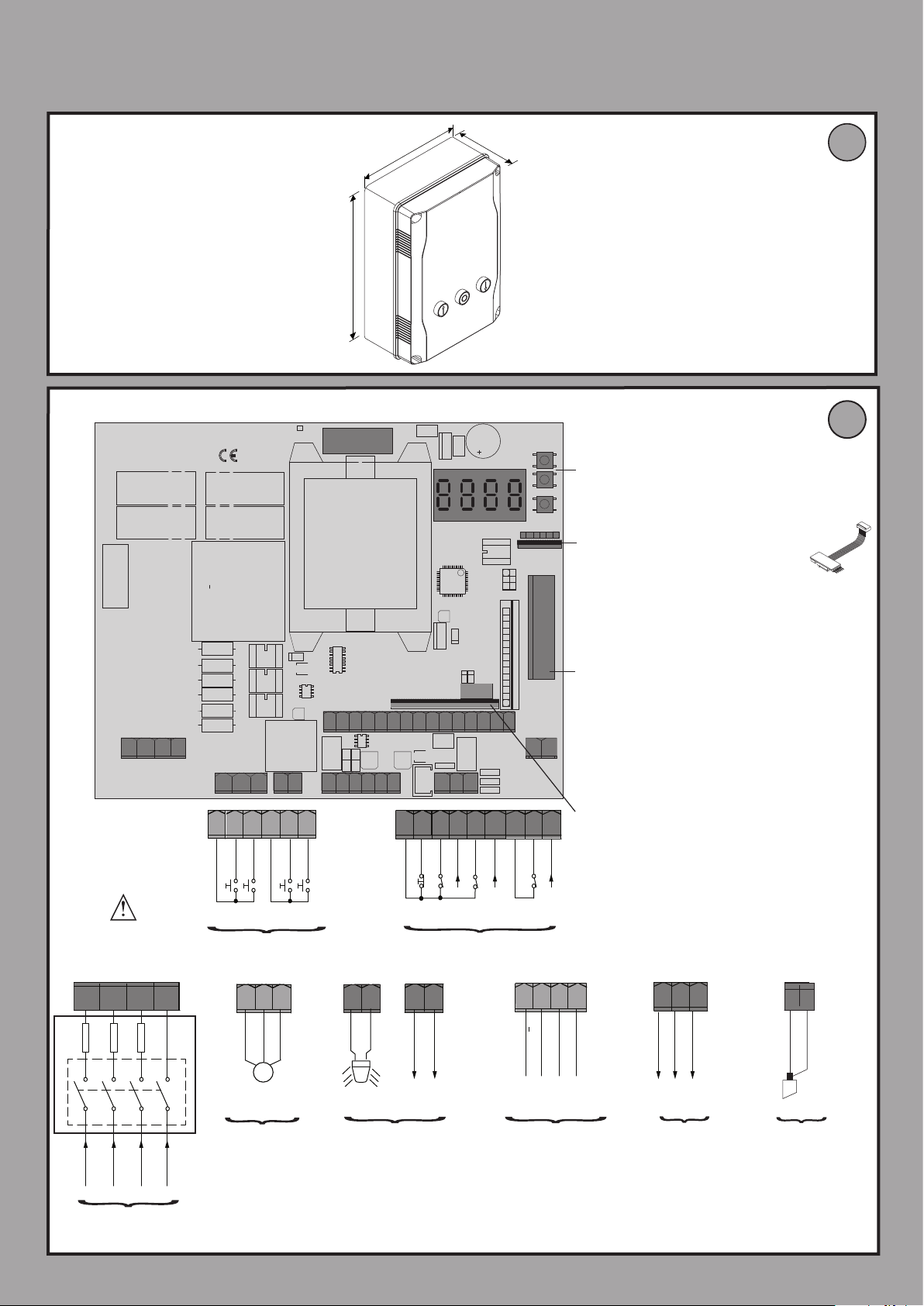
Congurazione degli ingressi di sicurezza
Logica SAFE= 0 - Ingresso congurato come Phot, fotocellula. (Fig.F, rif.1).
Consente la connessione di dispositivi non dotati di contatto supplementare di verica. In caso di oscuramento, le fotocellule sono attive sia in apertura che in chiusura. Un oscuramen-
to della fotocellula in chiusura, inverte il moto solo dopo il disimpegno della fotocellula. Se non si utilizza lasciare il ponticello inserito.
Logica SAFE= 1 - Ingresso congurato come Phot test, fotocellula vericata. (Fig.F, rif.2).
Attiva la verica delle fotocellule ad inizio manovra. In caso di oscuramento, le fotocellule sono attive sia in apertura che in chiusura. Un oscuramento della fotocellula in chiusura,
inverte il moto solo dopo il disimpegno della fotocellula.
Logica SAFE= 2 - Ingresso congurato come Phot op, fotocellula attiva solo in apertura. (Fig.F, rif.1).
Consente la connessione di dispositivi non dotati di contatto supplementare di verica. In caso di oscuramento è escluso il funzionamento della fotocellula in chiusura. In fase di aper-
tura blocca il moto per la durata dell’oscuramento della fotocellula. Se non si utilizza lasciare il ponticello inserito.
Logica SAFE= 3 - Ingresso congurato come Phot op test, fotocellula vericata attiva solo in apertura (Fig.F, rif.2).
Attiva la verica delle fotocellule ad inizio manovra. In caso di oscuramento è escluso il funzionamento della fotocellula in chiusura. In fase di apertura blocca il moto per la durata
dell’oscuramento della fotocellula.
Logica SAFE= 4 - Ingresso congurato come Phot cl, fotocellula attiva solo in chiusura. (Fig.F, rif.1).
Consente la connessione di dispositivi non dotati di contatto supplementare di verica. In caso di oscuramento è escluso il funzionamento della fotocellula in apertura. In fase di chiu-
sura, inverte immediatamente. Se non si utilizza lasciare il ponticello inserito.
Logica SAFE= 5 - Ingresso congurato come Phot cl test, fotocellula vericata attiva solo in chiusura (Fig.F, rif.2).
Attiva la verica delle fotocellule ad inizio manovra. In caso di oscuramento è escluso il funzionamento della fotocellula in apertura. In fase di chiusura, inverte immediatamente.
Logica SAFE= 6 - Ingresso congurato come Bar, costa sensibile. (Fig.F, rif.3).
Consente la connessione di dispositivi non dotati di contatto supplementare di verica. Il comando inverte il movimento per 2 sec. Se non si utilizza lasciare il ponticello inserito
Logica SAFE= 7 - Ingresso congurato come Bar, costa sensibile vericata (Fig.F, rif.4).
Attiva la verica delle coste sensibili ad inizio manovra. Il comando inverte il movimento per 2 sec.
Logica SAFE= 8 - Ingresso congurato come Bar 8k2 (Fig.F, rif.5). Ingresso per bordo resistivo 8K2.
Il comando inverte il movimento per 2 sec.
Altermine di questaoperazionela centraledicomando avràautomaticamente
impostato i valori ottimali di coppia. Vericarli ed eventualmente modicarli
come descritto in programmazione.
Attenzione!! Durante l’autosettaggio la funzione di rileva
mentoostacolinonèattiva,l’installatoredevecontrollareilmovimento
dell’automazione ed impedire a persone o cose di avvicinarsi o sostare nel
raggio di azione dell’automazione.
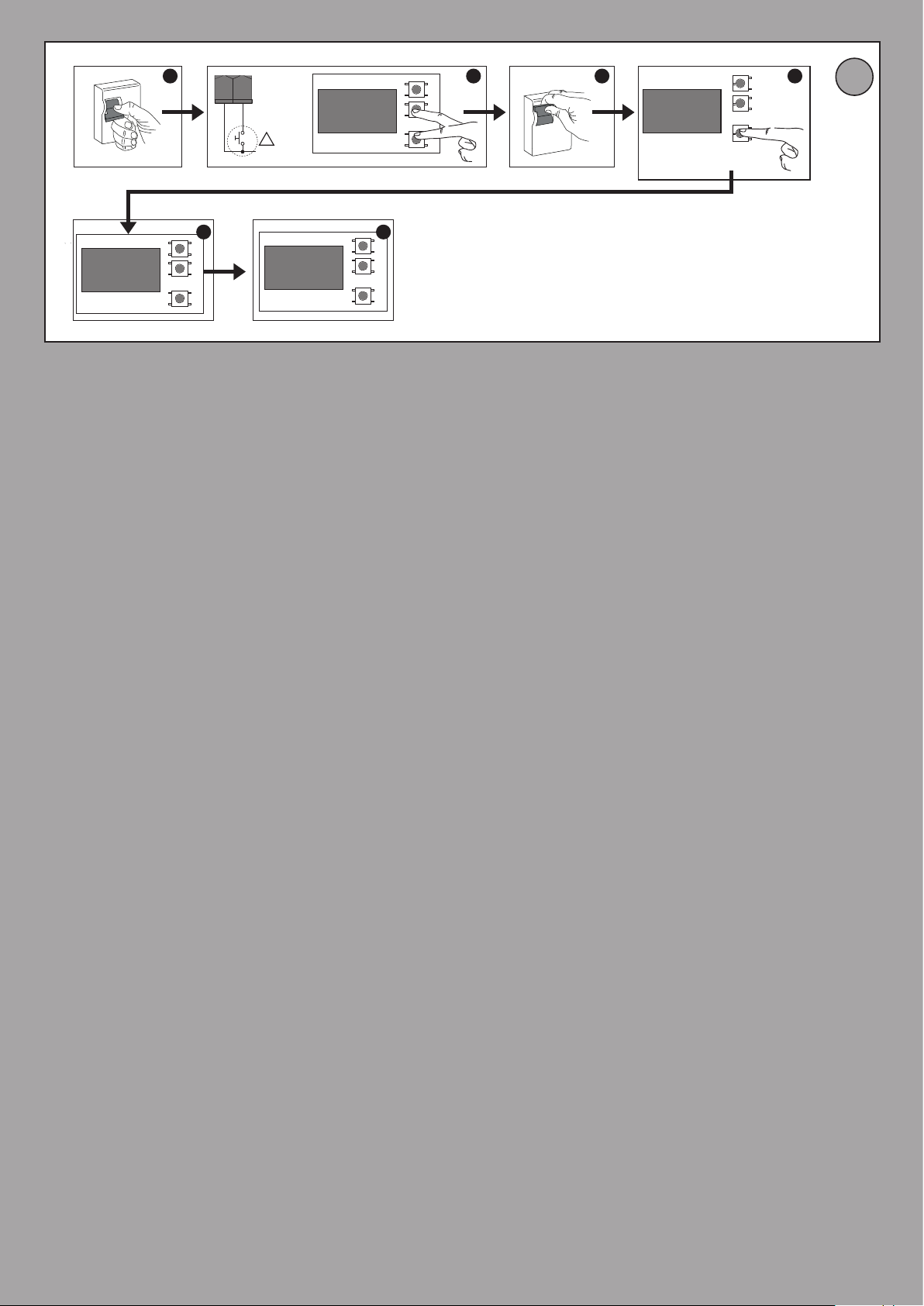
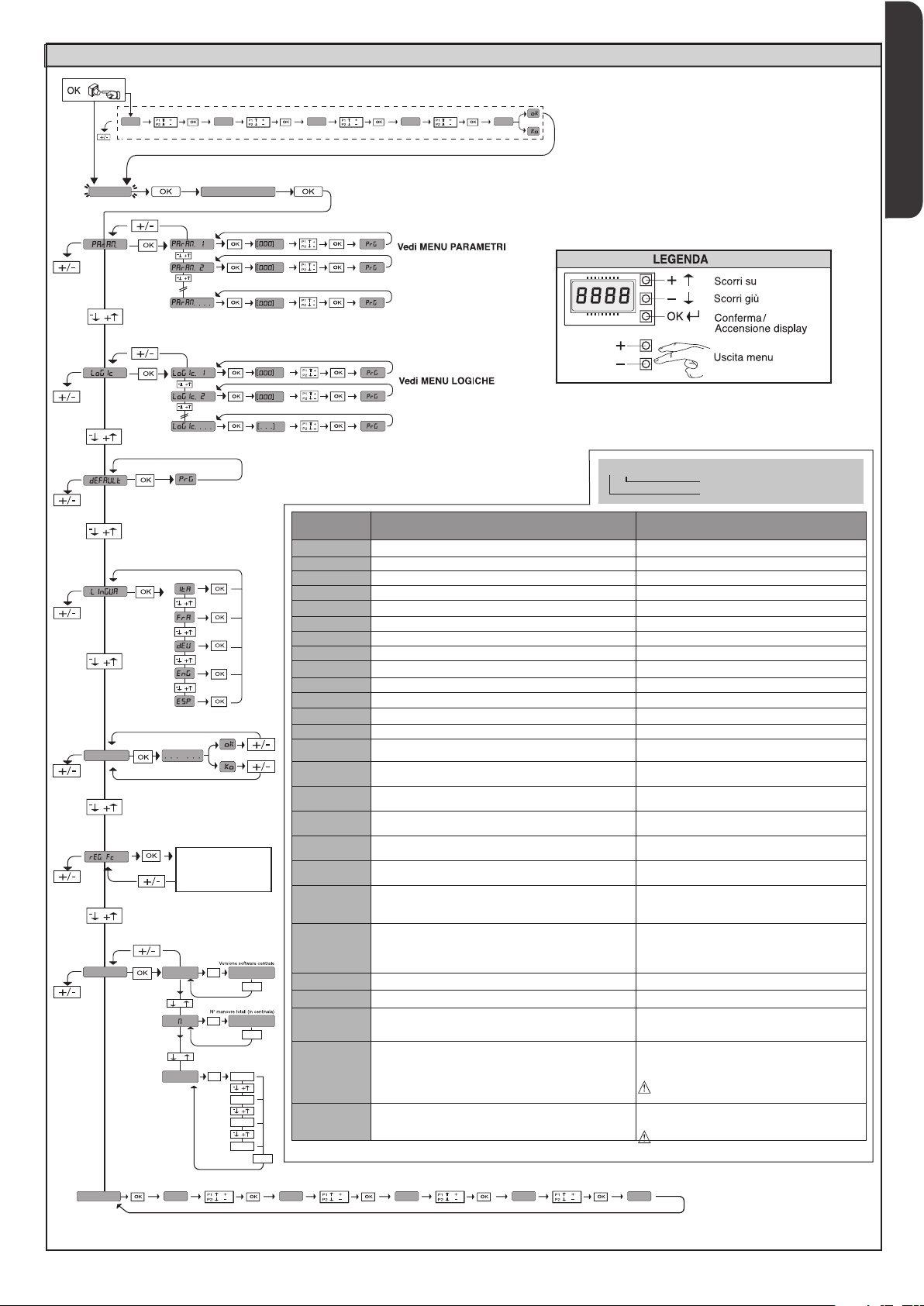
7.6) MENU REGOLAZIONE FINECORSA (REG. FC) (Fig.D)
Fasi della regolazione dei necorsa:
1) Posizionarsi su REG FC e confermare con OK.
2) Il display indica CLOSE, tramite i tasti SU e GIU, portare la porta nella posizione
di necorsa di chiusura. Confermare con OK, il display indica PRG.
3) Se il display lo richiede, agire sulla ghiera di regolazione: in senso antiorario
se il display indica UP, in senso orario se il display indica DOWN. Quando si
raggiunge la posizione corretta, il display indica OK. Confermare con il tasto
OK, il display indica PRG.
4) Il display indica OPEN, tramite i tasti SU e GIU, portare la porta nella posizione
di necorsa di apertura. Confermare con OK, il display indica PRG.
Se il display indica KO, signica che la regolazione non è andata a buon ne.
Le cause possono essere:
- pressione del tasto ESC prima della ne della regolazione
- corsa memorizzata troppo corta
7.7 MENU STATISTICHE
Consente di visualizzare la versione della scheda, il numero di manovre totali (in
centinaia), e gli ultimi 30 errori (le prime 2 cifre indicano la posizione, le ultime 2 il
codice errore). L’errore 01 è quello più recente.
6) DISPOSITIVI DI SICUREZZA
Nota: utilizzare solamente dispositivi di sicurezza riceventi con contatto
in libero scambio.
6.1) DISPOSITIVI VERIFICATI Fig. F
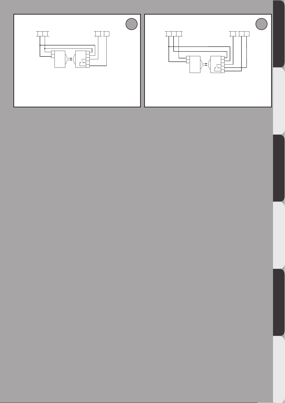
6.2) COLLEGAMENTO DI 1 COPPIA DI FOTOCELLULE NONVERIFICATE Fig. C1
6.3) COLLEGAMENTO DI 1 COPPIA DI FOTOCELLULE VERIFICATE Fig. C2
7 ACCESSO AI MENU: FIG. 1
7.1) MENU PARAMETRI PARA TABELLA“A” PARAMETRI
7.2) MENU LOGICHE LOGICTABELLA“B”LOGICHE
7.3 MENU DEFAULT default
Riporta la centrale ai valori preimpostati dei DEFAULT. Dopo il ripristino è neces-
sario eettuare un nuovo AUTOSET.
7.4 MENU LINGUA lingua
Consente di impostare la lingua del programmatore a display.
7.5 MENU AUTOSET AUTOset
•
Dare avvio ad una operazione di autosettaggio portandosi nell’apposito menu.
• Non appena premuto il pulsante OK viene visualizzato il messaggio “.... .... ....”,
la centrale comanda una manovra di apertura seguita da una manovra di
chiusura, durante la quale viene automaticamente settato il valore minimo di
coppia necessario al movimento dell’anta.
Durante questa fase è importante evitare l’oscuramento delle fotocellule,
nonchè l’utilizzo dei comandi START, STOP e del display.
LEO B CBB 3 400 W 01- 9
D811849 00100_04