BFT SHYRA AC SL User manual

ISTRUZIONI DI INSTALLAZIONE
INSTALLATION MANUAL
INSTRUCTIONS D’INSTALLATION
MONTAGEANLEITUNG
INSTRUCCIONES DE INSTALACION
INSTALLATIEVOORSCHRIFTEN
QUADRO COMANDO
CONTROL PANEL
CENTRALE DE COMMANDE
SELBSTÜBERWACHENDE STEUERUNG
CUADRO DE MANDOS
BEDIENINGSPANEEL
Attenzione! Leggere attentamente le “Avvertenze”all’interno! Caution! Read“Warnings”inside carefully! Attention! Veuillez lire attentivement les Avertissements qui se trouvent à l’intérieur!
Achtung! Bitte lesen Sie aufmerksam die„Hinweise“ im Inneren! ¡Atención¡ Leer atentamente las “Advertencias”en el interior! Let op! Lees de“Waarschuwingen” aan de binnenkant zorgvuldig!
D812090 00100_09 15-06-21
SHYRA AC SL / SHYRA AC SL 120
SHYRA AC BA / SHYRA AC BA 120

2x0.75mm
2
3x1.5mm
2
RG58
3x1.5mm
2
3x1.5mm
2
5x0,75mm
2
2x1.5mm
2
A
BC
JP3
24V
2
1TX1 2
1
RX1
4
5
3
50 51
70 72
0V ~
24V ~
24 VSafe
COM
START
(SHYRA AC SL)
START/CLOSE
(SHYRA AC BA)
OPEN
NO
NO
PHOT
STOP
COM
FAULT 1
BAR
FAULT 2
NC
NC
NC
LN
M
+ REF SWE
230V
max 40W
SWC
SWO
DIP3=OFF
L N 10 1211 41 4342 50 5251
2261
70 7271 73 757420 21
c
60
4110 11 12 20 21L N 42 43 50
Y
51 52
61 62 70 71 72 73 74 75
Y #
#
ANT
SHIELD
80 cm
100 cm
38mm
70mm
32 cm
22 cm
5m Moovi-50
6m Moovi-50+ATG6
3m Moovi-30
SHYRA AC BA / SHYRA AC BA 120SHYRA AC SL / SHYRA AC SL 120
F2
F1
60
INSTALLAZIONE VELOCE-QUICK INSTALLATION-INSTALLATION RAPIDE
SCHNELLINSTALLATION-INSTALACIÓN RÁPIDA - SNELLE INSTALLATIE
100mAT (~ 230V)
200mAT (~ 120V)
F1
F2
5 AF (~ 230V)
10 AF (~ 120V)
PREDISPOSIZIONE TUBI, TUBE ARRANGEMENT, PRÉDISPOSITION DES TUYAUX, VORBEREITUNG DER LEITUNGEN,
DISPOSICIÓN DE TUBOS, VOORBEREIDING LEIDINGEN.
Alimentazione
Power supply
Alimentation
Stromversorgung
Alimentación
Voeding
Motore
Motor
moteur
Motor
Eindaanslag
Encoder
Alimentazione accessori
Accessories power supply
Alimentation des accessoires
Stromversorgung Zubehör
Alimentación accesorios
Voeding accessoires
Comandi
Commands
Commandes
Bedienelemente
Mandos
Commando’s
Antena
Κεραία
Antena
Anténa
Anten
Lampeggiante
Blinker
Clignotant
Warnblinkleuchte
Bombilla
Knipperlicht
Connettore necorsa
Limit switch connector
Connecteur de n de course
Steckverbindung Endschalter
Conector nal de carrera
Connector eindaanslag
Sicurezze
Safety devices
Sécurités
Sicherheitsvorrichtungen
Dispositivos de seguridad
Veiligheden
Collegamento di 1 coppia di fotocellule non vericate,
per fotocellule vericate vedere pagine seguenti.
Connection of 1 couple of untested photocells,
for tested photocells see the following pages.
Connexion d’une paire de photocellules non vériées,
pour les photocellules vériées consultez les pages suivantes.
Anschluss von einem Paar nicht überprüfter Fotozellen,
für überprüfte Fotozelle siehe die folgenden Seiten.
Conexión de 1 par de fotocélulas no comprobadas,
para fotocélulas comproabdas véanse las siguientes páginas.
Aansluiting van 1 paar niet-geverieerde fotocellen.
Raadpleeg de volgende pagina’s voor geverieerde fotocellen.
2 - SHYRA
D812090 00100_09

E
D
1
1
2
2
START OK
S1
S2
RADIO
x1
S1
S2
RADIO
S1
S2
RADIO
S1
S2
RADIO
SHYRA AC SL / SHYRA AC SL 120
SHYRA AC BA / SHYRA AC BA 120
10 1211
M
41 4342
N
N R M
B M
10 1211
M
M B N
10 1211
M
N B M
41 4342
10 1211
M
M
N M R
B N
verso di apertura: destra
opening direction: right
sens de l’ouverture : droite
Önungsrichtung: rechts
sentido de apertura: derecha
openingsrichting: rechtsverso
Fisso
Steadily lit
Fixe
Ununterbrochen an
Fijo
Continu
Lampeggio continuo
Continuous ashing
Clignotement continu
Kontinuierliches Blinken
Parpadeo continuo
Continu knipperen
MONTAGGIO ASTA SINISTRA, ASSEMBLY OF LEFT BOOM,
MONTAGE DE LA BARRE GAUCHE, LINKS MONTAGE DER STANGE,
MONTAJE MÁSTIL IZQUIERDA, MONTAGE LINKSERSTANG.
MONTAGGIO ASTA DESTRA, ASSEMBLY OF RIGHT BOOM,
MONTAGE DE LA BARRE DROITE, RECHTE MONTAGE DER STANGE,
MONTAJE MÁSTIL DERECHO, MONTAGE RECHTERSTANG.
verso di apertura: sinistra
opening direction: left
sens de l’ouverture : gauche
Önungsrichtung: links
sentido de apertura: izquierda
openingsrichting: links
MEMORIZZAZIONE RADIOCOMANDO/MEMORIZING REMOTE CONTROLS/MÉMORISATION RADIOCOMMANDE
ABSPEICHERUNG DER FERNBEDIENUNG /MEMORIZACIÓN DEL RADIOMANDO/MEMORIZAÇÃO DO RADIOCOMANDO
M B N
MARRONE BLU NERO
BROWN BLUE BLACK
MARRON BLEU NOIR
BRAUN BLAU SCHWARZ
MARRÓN AZUL NEGRO
BRUIN BLAUW ZWART
M B N
MARRONE BLU NERO
BROWN BLUE BLACK
MARRON BLEU NOIR
BRAUN BLAU SCHWARZ
MARRÓN AZUL NEGRO
BRUIN BLAUW ZWART
LEGENDA - KEY - LÉGENDE - LEGENDE - LEYENDA - LEGENDA
M B N R
MARRONE BLU NERO ROSSO
BROWN BLUE BLACK RED
MARRON BLEU NOIR ROUGE
BRAUN BLAU SCHWARZ ROT
MARRÓN AZUL NEGRO ROJO
BRUIN BLAUW ZWART ROOD
M B N R
MARRONE BLU NERO ROSSO
BROWN BLUE BLACK RED
MARRON BLEU NOIR ROUGE
BRAUN BLAU SCHWARZ ROT
MARRÓN AZUL NEGRO ROJO
BRUIN BLAUW ZWART ROOD
SHYRA - 3
D812090 00100_09

G
50 51 52 70 71 72 73 74 75
24V ~
24V ~
24 VSafe
COM
PHOT
BAR
STOP
FAULT 1
FAULT 2
NC
NC
NC
PHOT
1
2
1
2
3
4
5
51 TX1 RX1
1
2
1
2
3
4
5
52
50 TX1 RX1
1
2
1
2
3
4
5
TX1 RX1
1
2
1
2
3
4
5
TX2 RX2
1
2
1
2
3
4
5
TX1 RX1
1
2
1
2
3
4
5
TX1 RX1
1
2
1
2
3
4
5
TX1 RX1
1
2
1
2
3
4
5
TX2 RX2
1 PHOT / 1 PHOT CL
1 PHOT / 1 PHOT CL
2 PHOT / 2 PHOT CL
BAR 8K2
50
52
50
52
50
51
50
51
50
51
50
51
50
70
72
70
72
73
70
70
72
73
BAR
Bar 1
1
2
3
4
5
6
Bar 1
1
2
3
4
5
Bar 2
1
2
3
4
5
Bar 1
1
2
3
4
5
6
6
6
Bar 1
1
2
3
4
5
6
Bar 1
1
2
3
4
5
Bar 2
1
2
3
4
5
Bar 1
1
2
3
4
5
6
6
6
1 BAR/ 1BAR CL
51
51
50
51
50
51
50
52
52
52
74
70
74
70
75
74
70
51
50
70
75
70
74 8,2Kohm 5%
SAFETY EDGE SAFETY EDGE
DIP2 OFF
DIP4 OFFDIP4 ON
DIP2 ON
DIP3 OFFDIP3 ON
F
100
195
237
1 BAR TEST/ 1 BAR CL TEST
2 BAR TEST/ 2 BAR CL TEST
BAR 8K2/ BAR CL 8K2
4 - SHYRA
D812090 00100_09

ITALIANO
MANUALE PER L’INSTALLAZIONE
1) GENERALITÀ
I quadri comandi SHYRA AC SL / SHYRA AC BA vengono forniti dal costruttore
con settaggio standard. Qualsiasi variazione, deve essere impostata mediante
congurazione dei TRIMMER e DIP SWITCH.
Le caratteristiche principali sono:
- Controllo di 1 motore monofase
- Ingressi separati per le sicurezze
- Ricevitore radio incorporato rolling-code con clonazione trasmettitori.
La scheda è dotata di una morsettiera di tipo estraibile per rendere più agevole
la manutenzione o la sostituzione.Viene fornita con una serie di ponti precablati
per facilitare l’installatore in opera. I ponti riguardano i morsetti: 70-71, 70-72,
70-74.Seimorsettisopraindicativengonoutilizzati,togliereirispettiviponti.
VERIFICA
I quadri comando SHYRA AC SL / SHYRA AC BA eettuano il controllo (verica)
dei relè di marcia e dei dispositivi di sicurezza (fotocellule) prima di eseguire ogni
ciclo di apertura e chiusura.
In caso di malfunzionamenti vericare il regolare funzionamento dei dispositivi
collegati e controllare i cablaggi.
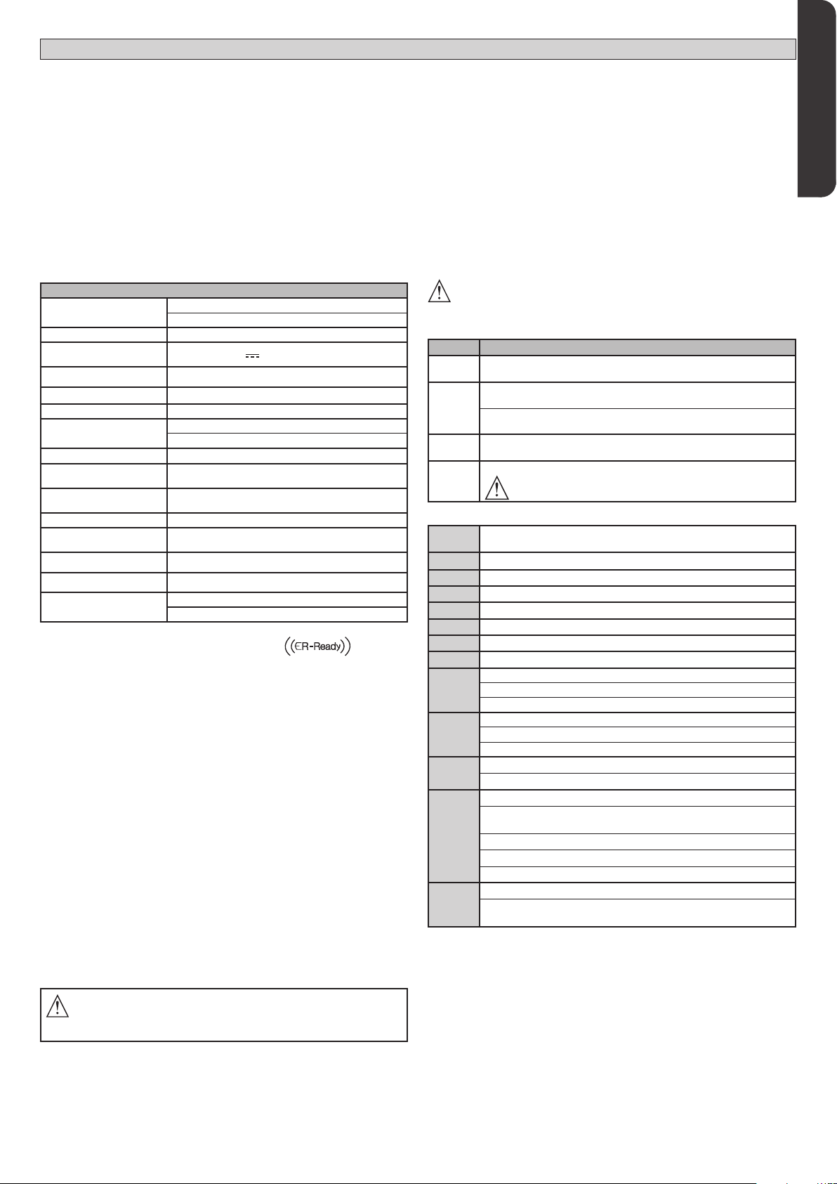
2) DATI TECNICI
Alimentazione 120V 60Hz (SHYRA AC SL / SHYRA AC BA 120V)
220-230V50/60Hz(SHYRAACSL/SHYRAACBA230V)
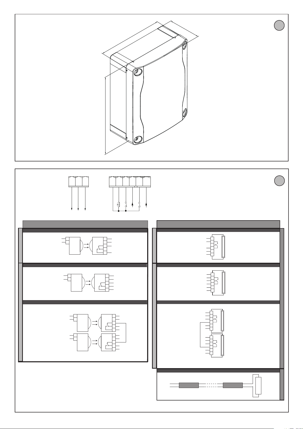
Dimensioni quadro Fig. F
Isolamento
rete/bassa tensione > 2MOhm 500V
Temperaturadi funzionamento
-20 / +55°C
Rigidità dielettrica rete/bt 3750V~ per 1 minuto
Alimentazione accessori 24V~ (0,2A assorbimento max)
AUX 0 - Lampeggiante
Contatto alimentato
120V~ 40W max (SHYRA AC SL / SHYRA AC BA 120V)
230V~ 40W max (
SHYRA AC SL / SHYRA AC BA 230V
)
Fusibili Fig. C
Radioricevente
Rolling-Code incorporata frequenza 433.92MHz
Impostazione parametri
e logiche TRIMMER + DIP SWITCH
N.° combinazioni 4 miliardi
N.°max.radiocomandi
memorizzabili 63
Tempo di lavoro pedonale
8 s.
Potenza massima 500W
Tempo di lavoro massimo 120s - SHYRA AC SL
10s - SHYRA AC BA
Versioni trasmettitori utilizzabili:
Tutti i trasmettitori ROLLING CODE compatibili con
3) PREDISPOSIZIONE TUBI FIG.A
Predisporre l’impianto elettrico facendo riferimento alle norme vigenti per gli
impiantielettriciCEI64-8,IEC364,armonizzazioneHD384edaltrenormenazionali.
4) COLLEGAMENTO MORSETTIERA FIG. C
Per lo schema elettrico e per la sezione dei cavi fare riferimento al manuale
dell’attuatore.
Passati gli adeguati cavi elettrici nelle canalette e ssati i vari componenti dell’au-
tomazioneneipuntiprescelti,sipassa allorocollegamentosecondoleindicazioni
e gli schemi riportati nei relativi manuali istruzione. Eettuare la connessione
della fase, del neutro e della terra (obbligatoria).
AVVERTENZE - Nelle operazioni di cablaggio ed installazione riferirsi alle norme
vigenti e comunque ai principi di buona tecnica. I conduttori alimentati con
tensioni diverse, devono essere sicamente separati, oppure devono essere
adeguatamente isolati con isolamento supplementare di almeno 1mm.
I conduttori devono essere vincolati da un ssaggio supplementare in prossimità
dei morsetti, per esempio mediante fascette. Tutti i cavi di collegamento devono
essere mantenuti adeguatamente lontani dai dissipatori.
ATTENZIONE! Per il collegamento alla rete, utilizzare cavo multipolare di
sezione minima 3x1.5mm2e del tipo previsto dalle normative vigenti.
Per il collegamento dei motori, utilizzare cavo di sezione minima 1,5 mm2
e del tipo previsto dalle normative vigenti. Il cavo deve essere almeno pari
a H05RN-F.
5) DISPOSITIVI DI SICUREZZA
Nota: utilizzare solamente dispositivi di sicurezza riceventi con contatto
in libero scambio.
5.1) DISPOSITIVI VERIFICATI Fig. G
5.2) COLLEGAMENTO DI 1 COPPIA DI FOTOCELLULE NON VERIFICATE Fig. B
ATTENZIONE!
I valori delle forze di impatto previste dalla norma EN12453 sono rispettati
solamente con l’utilizzo di coste sensibili (attive) collegate alla scheda.
6) MEMORIZZAZIONE RADIOCOMANDO Fig. D
RADIO
- NOTA IMPORTANTE: CONTRASSEGNARE IL PRIMO TRASMETTITORE ME-
MORIZZATO CON IL BOLLINO CHIAVE (MASTER).
Il primo trasmettitore, nel caso di programmazione manuale, assegna il CODICE
CHIAVE DELLA RICEVENTE; questo codice risulta necessario per poter eettuare
la successiva clonazione dei radiotrasmettitori.
La ricevente di bordo incorporato Clonix dispone inoltre di alcune importanti
funzionalità avanzate:
• Clonazione del trasmettitore master (rolling-code).
• Clonazione per sostituzione di trasmettitori già inseriti nella ricevente.
• Gestione database trasmettitori.
• Gestione comunità di ricevitori.
Perl’utilizzodiquestefunzionalitàavanzatefateriferimentoalleistruzionidelpro-
grammatorepalmareuniversaleedallaGuidageneraleprogrammazioniriceventi.
7) INVERSIONE DELLA DIREZIONE DI APERTURA (Fig. E)
8 PROCEDURA DI REGOLAZIONE
Prima dell’accensione vericare i collegamenti elettrici.
Eseguire l’impostazione dei seguenti parametri:
Tempo Chiusura Automatica,
Tempo Lavoro (solo per SHYRA AC SL)
Eseguire l’impostazione delle logiche.
ATTENZIONE!Un’errataimpostazionepuòcrearedanniapersone,animaliocose.
ATTENZIONE: Verificare che il valore della forza d’impatto
misuratoneipuntiprevistidallanormaEN12445, siainferiorea quanto
indicato nella norma EN 12453.
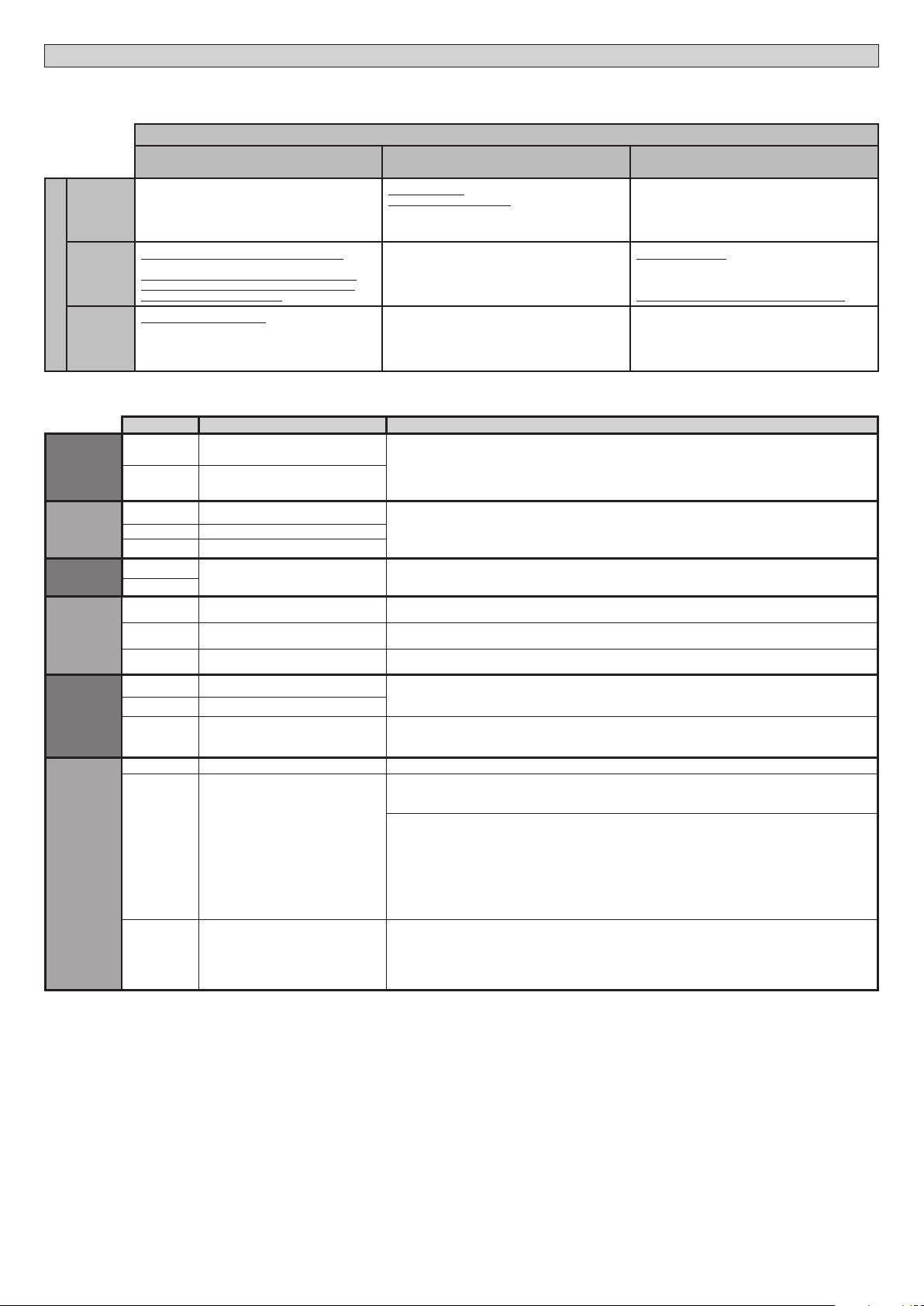
TASTI
TASTI Descrizione
S1 Aggiungi Tasto start
associa il tasto desiderato al comando Start.
S2
Aggiungi Tasto pedonale (SHYRA AC SL)
associa il tasto desiderato al comando pedonale.
Aggiungi Tasto open (SHYRA AC BA)
associa il tasto desiderato al comando open.
S2
>5s Convalidalemodicheapportateallaregolazionedeiparametri
e alle logiche di funzionamento.
S1+S2
>10s
Elimina Lista
ATTENZIONE! Rimuove completamente dalla memoria della
ricevente tutti i radiocomandi memorizzati.
SEGNALAZIONI LEDS:
POWER Rimane acceso: - Presenza di rete - Scheda alimentata - Fusibili
integri
START Acceso: attivazione ingresso START
OPEN Acceso: attivazione ingresso pedonale OPEN
STOP Spento: attivazione ingresso STOP
PHOT Spento: attivazione ingresso fotocellula PHOT
FAULT 1 Diagnostica dell’ingresso verica sicurezze ingresso PHOT
BAR Spento: attivazione ingresso costa BAR
FAULT 2 Diagnostica dell’ingresso verica sicurezze ingresso BAR
SWC
Spento: anta tutta chiusa
Acceso: il necorsa del motore è libero
Lampeggiante: ne del tempo di lavoro in chiusura
SWO
Spento: anta tutta aperta
Acceso: il necorsa del motore è libero
Lampeggiante: ne del tempo di lavoro in apertura
ERR SPENTO: nessun errore
ACCESO: vedi tabella diagostica errori
RADIO
(VERDE)
Spento: programmazione radio disattiva
Lampeggiante solo led Radio: Programmazione radio attiva, atte-
sa tasto nascosto.
Lampeggiante sincrono con led Set: Cancellazione radiocomandi in corso
Acceso: programmazione radio attiva, attesa tasto desiderato.
Acceso 1s: attivazione canale della ricevente radio
SET
Acceso: vedi tabella diagnostica errori
Lampeggiante sincrono con led Radio: cancellazione radiocoman-
di in corso
SHYRA - 5
D812090 00100_09

MANUALE PER L’INSTALLAZIONE
Morsetto Denizione Descrizione
Alimentazione
L FASE
Alimentazione monofase
N NEUTRO
Motore
10
MARCIA + CONDENSATORE
Collegamento motore e condensatore
11 COM
12
MARCIA + CONDENSATORE
Aux
20
AUX 0 -CONTATTO ALIMENTATO
230V (N.O.) (40W MAX) Uscita per lampeggiante.
Il contatto rimane chiuso durante la movimentazione delle ante.
21
Finecorsa
41 +REF SWE Comune necorsa
42 SWC Finecorsa di chiusura SWC (N.C.).
43 SWO Finecorsa di apertura SWO (N.C.).
Alim.
Accessori
50 0V~ Uscita alimentazione accessori.
51 24V~
52 24 Vsafe
Uscita alimentazione per dispositivi di sicurezza vericati (trasmettitore fotocellule e trasmetti-
tore costa sensibile).
Uscita attiva solo durante il ciclo di manovra.
Comandi
60 Comune Comune ingressi START, OPEN
61 START
SHYRA AC SL
Pulsante di comando START (N.O.)
Funzionamento secondo logiche“Funzionamento residenziale / condominiale”
SHYRA AC BA
Se trimmer T2 al massimo:
Pulsante di comando START (N.O.)
Funzionamento secondo logiche“Funzionamento residenziale / condominiale”
Se trimmer T2 al minimo:
Pulsante di comando CLOSE (N.O.)
Il comando esegue una chiusura. Se il l’ingresso rimane chiuso, le ante rimangono chiuse
no all’apertura del contatto.
62 OPEN
Pulsante di comando OPEN (N.O.)
Il comando esegue un’apertura. Se il l’ingresso rimane chiuso, le ante rimangono aperte
no all’apertura del contatto. A contatto aperto l’automazione chiude dopo il tempo di
tca, se attivato.
TABELLA ERRORI:
Led ERR
Acceso Lampeggiante lento Lampeggiante veloce
Led SET
Spento
Test Fotocellule,
Costa o Costa 8k2 fallito
-
Vericare collegamento fotocellule e/o impo-
stazioni logiche
Acceso
Erroreinternodicontrollosupervisionesistema
-
Provare a spegnere e riaccendere la scheda o
premere il pulsante S2. Se il problema persiste
contattare l’assistenza tecnica.
Errore necorsa
- vericare collegamenti dei necorsa
Lampeg-
giante
lento
Errore test hardware scheda
-
Vericare collegamenti al motore
- Problemi hardware alla scheda (contattare
l’assistenza tecnica)
Modicati parametri e/o Logiche di funziona-
mento premere per 5s S2 per convalidare.
6 - SHYRA
D812090 00100_09

ITALIANO
MANUALE PER L’INSTALLAZIONE
Morsetto Denizione Descrizione
Sicurezze
70 Comune Comune ingressi STOP, PHOT e BAR
71 STOP Il comando interrompe la manovra. (N.C.)
Se non si utilizza lasciare il ponticello inserito.
72 PHOT (*) Ingresso FOTOCELLULA (N.C.)
Funzionamento secondo le logiche“FOTOCELLULA/ FOTOCELLULA IN CHIUSURA”. Se non
si utilizza lasciare il ponticello inserito.
73 FAULT 1 Ingresso verica dispositivi di sicurezza collegati al PHOT.
74
BAR /
BAR CL /
BAR TEST /
BAR CL TEST /
BAR 8K2 /
BAR CL 8K2
(*)
Ingresso costa sensibile (N.C.)
Se non si utilizza lasciare il ponticello inserito
SHYRA AC SL
Dip
BAR/8K2 Dip
verica
ingresso
costa
Dip
funzionamento
costa
OFF OFF OFF Ingresso NC, senza verica, inversione in
apertura e chiusura (BAR)
OFF OFF ON Ingresso NC, senza verica, inversione solamente
chiusura, in apertura si ottiene lo stop (BAR CL)
OFF ON OFF Ingresso NC, con verica, inversione in apertura e
chiusura (BARTEST)
OFF ON ON Ingresso NC, con verica, inversione solamente
chiusura, in apertura si ottiene lo stop (BAR CL
TEST)
ON OFF OFF Ingresso 8K2, inversione in apertura e chiusura
(BAR 8K2)
ON OFF ON Ingresso 8K2, inversione solamente chiusura, in
apertura si ottiene lo stop (BAR CL 8K2)
SHYRA AC BA
Dip
BAR/8K2 Dip
verica
ingresso
costa
OFF OFF Ingresso NC, senza verica, inversione solamente
chiusura, in apertura si ottiene lo stop (BAR CL)
OFF ON Ingresso NC, con verica, inversione solamente
chiusura, in apertura si ottiene lo stop (BAR CL TEST)
ON OFF Ingresso 8K2, inversione solamente chiusura, in
apertura si ottiene lo stop (BAR CL 8K2)
75 FAULT 2 Ingresso verica dispositivi di sicurezza collegati al BAR / BAR CL
Antenna
Y ANTENNA Ingresso antenna.
Usare una antenna accordata sui 433MHz. Per il collegamento Antenna-Ricevente usare
cavo coassiale RG58. La presenza di masse metalliche a ridosso dell’antenna, può distur-
bare la ricezione radio. In caso di scarsa portata del trasmettitore, spostare l’antenna in un
punto più idoneo.
# SHIELD
(*) Se si si installano dispositivi di tipo “D” (come deniti dalla EN12453), collegati in modalità non vericata, prescrivere una manutenzione obbligatoria
con frequenza almeno semestrale.
(*) Nell’Unione Europea applicare la EN12453 per i limiti di forza, e la EN12445 per il metodo di misura.
TABELLA “A” PARAMETRI
Ogni modica di parametri/logiche deve essere confermata dalla pressione di S2 > 5s
TRIMMER Parametro +
min. +
max. +
default
Descrizione
T1 Tempo chiusura
automatica [s] 0 120 0 Tempo di attesa prima della chiusura automatica.
NOTA: Impostare a 0 se non utilizzato.
T2 Tempo di lavoro
[s] 5 120 50%
SHYRA AC SL
Regola il tempo di lavoro dei motori, trascorso il quale, i motori si fermano.
Nel caso si impieghino necorsa elettrici, regolare per qualche secondo in più
rispetto al momento di arresto dell’anta del cancello.
SHYRA AC BA
Tempo di lavoro del/i motore/i sso a 15 secondi.
trimmer al minimo: ingresso 60-61 CLOSE.
trimmer al massimo: ingresso 60-61 START.
SHYRA - 7
D812090 00100_09

MANUALE PER L’INSTALLAZIONE
TABELLA “B” LOGICHE
Ogni modica di parametri/logiche deve essere confermata dalla pressione di S2 > 5s
DIP Logica Default Barrare il
settaggio
eseguito Descrizione
1Programmazione
radiocomandi ON
ON
Abilita la memorizzazione via radio dei radiocomandi:
1-
Premere in sequenza il tasto nascosto e il tasto normale (T1-T2-T3-T4) di un radiocomando già
memorizzato in modalità standard attraverso il menu radio.
2- Premere entro 10s il tasto nascosto ed il tasto normale (T1-T2-T3-T4) di un radiocomando da
memorizzare.
La ricevente esce dalla modalità programmazione dopo 10s, entro questo tempo è possibile inserire
ulteriori nuovi radiocomandi.
Questa modalità non richiede l’accesso al quadro comando.
IMPORTANTE: Abilita l’inserimento automatico di nuovi radiocomandi, cloni e replay.
OFF
Disabilita la memorizzazione via radio dei radiocomandi e l’inserimento automatico dei cloni.
I radiocomandi vengono memorizzati solo utilizzando l’apposito menu Radio o in automatico con i
replay.
IMPORTANTE: Disabilita l’inserimento automatico di nuovi radiocomandi, cloni
2 BAR / 8K2 OFF
ON Ingresso congurato come Bar 8k2 (Fig.G). Ingresso per bordo resistivo 8K2.
Il comando inverte il movimento per 1 sec.
OFF Ingresso congurato come Bar, costa sensibile (Fig.G).
Il comando inverte il movimento per 1 sec.
3Verica ingresso
fotocellula OFF ON
Abilita la verica delle sicurezze sugli ingressi PHOT.
(Fig.G)
OFF
Verica delle sicurezze sull’ingresso PHOT non abilitata.
(Fig.G)
4Verica ingresso
costa OFF ON Abilita la verica delle sicurezze sull’ingresso BAR. (Fig.G)
OFF Verica delle sicurezze sull’ingresso BAR non abilitata. (Fig.G)
5Fotocellule in
chiusura OFF
ON In caso di oscuramento è escluso il funzionamento della fotocellula in apertura. In fase di chiusura,
inverte immediatamente.
OFF
In caso di oscuramento, le fotocellule sono attive sia in apertura che in chiusura. Un oscuramento della foto-
cellula in chiusura, inverte il moto solo dopo il disimpegno della fotocellula.
6Funzionamento
ingresso costa OFF
SHYRA AC SL
ON Costa con inversione attiva solo in chiusura, durante l’apertura si ottiene lo stop del movimento
OFF
Costa con inversione attiva in entrambe le direzioni
SHYRA AC BA
ON NON UTILIZZATO
OFF
NON UTILIZZATO
7 Chiusura rapida OFF ON
SHYRA AC SL
Chiude dopo 3 secondi dal disimpegno delle fotocellule prima di attendere il termine del TCA
impostato
SHYRA AC BA
Chiude dopo 1 secondo dal disimpegno delle fotocellule prima di attendere il termine del TCA
impostato
OFF Logica non attiva
8Funzionamento
residenziale /
condominiale OFF
ON
Imposta il tipo
di funzionamento
dell’automazione:
ON = Condominiale
Reazione all’ingresso START (cablato o radio):
Residenziale Condominale
CHIUSA Apre Apre
IN CHIUSURA Stop Apre
APERTA Chiude Chiude
IN APERTURA Stop + TCA Nessun eetto
DOPO STOP Apre Apre
Reazione all’ingresso OPEN (cablato):
Residenziale Condominale
CHIUSA Apre Apre
IN CHIUSURA Apre Apre
APERTA Mantiene aperto + TCA Mantiene aperto + TCA
IN APERTURA Nessun eetto Nessun eetto
DOPO STOP Apre Apre
Reazione all’ingresso PEDONALE (radio):
Residenziale Condominale
CHIUSA Apre parziale Apre parziale
IN CHIUSURA Stop Apre parziale
APERTA Chiude Chiude
IN APERTURA Stop + TCA Nessun eetto
DOPO STOP Apre parziale Apre parziale
OFF OFF = Residenziale
8 - SHYRA
D812090 00100_09

ENGLISH
INSTALLATION MANUAL
1) GENERAL INFORMATION
The SHYRA AC SL / SHYRA AC BA control panel comes with standard factory
settings.
Any change must be set by means of the TRIMMER and DIP SWITCH settings.
Its main features are:
- Control of 1 single-phase motor
- Separate inputs for safety devices
- Built-in radio receiver rolling code with transmitter cloning.
The board has a terminal strip of the removable kind to make maintenance or re-
placementeasier.Itcomeswitha seriesofprewiredjumperstomaketheinstaller’s
job on site easier. The jumpers concern terminals: 70-71, 70-72, 70-74. If the
above-mentioned terminals are being used, remove the relevant jumpers.
TESTING
The SHYRA AC SL / SHYRA AC BA panel controls (checks) the start relays and
safety devices (photocells) before performing each opening and closing cycle.
If there is a malfunction, make sure that the connected devices are working
properly and check the wiring.
2) TECHNICAL SPECIFICATIONS
Power supply
120V60Hz(SHYRAACSL/ SHYRAACBA120V)
220-230V 50/60 Hz
(SHYRA AC SL / SHYRA
AC BA 230V)
Panel dimensions Fig. F
Low voltage/mains insulation > 2MOhm 500V
Operating temperature range -20 / +55°C
Dielectric rigidity mains/LV 3750V~ for 1 minute
Accessories power supply 4V~ (demand max. 0,2A)
AUX 0 - Flashing
Contact powered
120V~ 40W max (
SHYRA AC SL / SHYRA AC
BA 120V
)
230V~ 40W max (SHYRA AC SL / SHYRA AC
BA 230V)
Fuses Fig. C
Built-in Rolling-Code
radio-receiver frequency 433.92MHz
Setting of parameters and logics TRIMMER + DIP SWITCH
N° of combinations 4 billion
Max. n° of remotes that can be
memorized 63
Pedestrian work time 8 s.
Maximum power 500W
Maximum work time 120s - SHYRA AC SL
10s - SHYRA AC BA
Usable transmitter versions:
All ROLLING CODE transmitters compatible with .
3) TUBE ARRANGEMENT Fig. A
Install the electrical system referring to the standards in force for electrical systems
CEI 64-8, IEC 364, harmonization document HD 384 and other national standards.
4) TERMINAL BOARD WIRING Fig. C
For the electric diagram and the cross section of the cables refer to the
manual of the actuator.
Once suitable electric cables have been run through the raceways and the auto-
mated device’s various components have been fastened at the predetermined
points,thenext stepis toconnectthem asdirectedand illustratedin thediagrams
containedin the relevantinstruction manuals. Connectthe live,neutral and earth
wire (compulsory).
WARNINGS - When performing wiring and installation, refer to the standards
in force and, whatever the case, apply good practice principles. Wires carrying
dierent voltages must be kept physically separate from each other, or they must
be suitably insulated with at least 1mm of additional insulation.
Wires must be secured with additional fastening near the terminals, using devi-
ces such as cable clamps. All connecting cables must be kept far enough away
from dissipaters.
WARNING! For connection to the mains power supply, use a multicore cable
with a cross-sectional area of at least 3x1.5mm2of the kind provided for by
the regulations in force.
To connect the motors, use a cable with a cross-sectional area of at least
1.5mm2of the kind provided for by the regulations in force.
The cable must be type H05RN-F at least.
5) SAFETY DEVICES
Note: only use receiving safety devices with free changeover contact.
5.1) TESTED DEVICES Fig.G
5
.2 CONNECTION OF 1 PAIR OF NONTESTED PHOTOCELLS FIG. B
WARNING!
The values of the impact force according to EN 12453 are only observed with
the use of safety edges (active) connected to the board.
6 MEMORIZING TRANSMITTERS FIG. D
RADIO
- IMPORTANT NOTE: THE FIRST TRANSMITTER MEMORIZED MUST BE
IDENTIFIED BY ATTACHING THE KEY LABEL (MASTER).
In the event of manual programming, the rst transmitter assigns the RECEIVER’S
KEY CODE: this code is required to subsequently clone the radio transmitters.
TheClonixbuilt-inon-boardreceiveralsohasanumberofimportantadvancedfeatures:
• Cloning of master transmitter (rolling code).
• Cloning to replace transmitters already entered in receiver.
• Transmitter database management.
• Receiver community management.
To use these advanced features, refer to the universal handheld programmer’s
instructions and to the general receiver programming guide.
7) REVERSING THE OPENING DIRECTION (Fig.E)
8 ADJUSTMENT PROCEDURE
Before turning the unit on, check electrical connections.
- Set the following parameters:
Automatic Closing Time,
Work Time (for SHYRA AC SL only).
- Set the logics.
WARNING! Incorrect settings can result in damage to property and injury
to people and animals.
WARNING: Check that the force of impact measured at the points pro-
vided for by standard EN 12445 is lower than the value laid down by
standard EN 12453.
KEYS
KEYS Description
S1 Add Start Key
associates the desired key with the Start command.
S2
Add Pedestrian Key (SHYRA AC SL)
associates the desired key with the pedestrian command.
Add Open key (SHYRA AC BA)
associates the desired key with the open command.
S2
>5s Conrms the changes made to parameter settings and operating
S1+S2
>10s Erase List
WARNING! Erases all memorized transmitters from the
receiver’s memory.
LED INDICATORS:
POWER Steadily lit: - Mains power on - Board powered - Fuses intact
START Lit: START input activated
OPEN Lit: OPEN pedestrian input activated
STOP Unlit: STOP input activated
PHOT Unlit: PHOT photocell input activated
FAULT 1 PHOT input safety device test input diagnostics
BAR Unlit: BAR safety edge input activated
FAULT 2 BAR input safety device test input diagnostics
SWC
Unlit: leaf fully closed
Lit: motor limit switch is disengaged
Flashing: end of the work time while closing
SWO
Unlit: leaf fully open
Lit: motor limit switch is disengaged
Flashing: end of the work time while opening
ERR Unlit: no error
LIT: see error diagnostics table
RADIO
(GREEN)
Unlit: remote programming not active
Radio LED only ashing: Remote programming active, waiting for
hidden key.
Flashing in sync with Set LED: Transmitter deletion in progress
Lit: remote programming active, waiting for desired key.
Lit 1s: Radio receiver channel activated
SET Lit: see error diagnostics table
Flashing in sync with Radio LED: Transmitter deletion in progress
SHYRA - 9
D812090 00100_09

INSTALLATION MANUAL
Terminal Denition Description
Power
supply
LLINE
Single-phase power supply
NNEUTRAL
Motor
10 START + CONDENSER
Motor and condenser connection
11 COM
12 START + CONDENSER
Aux
20 AUX 0 – POWERED CONTACT
230V (N.O.) (40W MAX) Exit due to FLASHING LIGHT
Contact stays closed while leaves are operating.
21
Limit
switches
41 +REF SWE Limit switch common
42 SWC Closing limit switch SWC (N.C.)
43 SWO Opening limit switch SWO (N.C.)
Accessories
power supply
50 0V- Accessories power supply output.
51 24V+
52 24 Vsafe+
Tested safety device power supply output (photocell transmitter and safety edge transmitter).
Output act ive only during operating cycle.
Commands
60 Common START and OPEN inputs common
61 START
SHYRA AC SL
START command button (N.O.).
Operation according to “Residential / apartment building operation” logic
SHYRA AC BA
If trimmer T2 at maximum:
START command button (N.O.).
Operation according to “Residential / apartment building operation” logic
If trimmer T2 at minimum:
CLOSE command button (N.O.).
The command causes the device to close. If the input stays closed, the leaves stay open until
the contact is opened.
62 OPEN
OPEN command button (N.O.).
Gate opened with this command. If the input stays closed, the leaves stay open until the
contact is opened.
When the contact is open, the automated device closes following the TCA time, where
activated.
TABLE ERR
Led ERR
Lit slow ashing fast ashing
Led SET
Unlit
Photocell test,
Costa o Costa 8k2 failed
- Check photocell connection and/or logic
settings
Lit
Internal system supervision control error
- Try switching the card o and on again or
press the S2 button. If the problem persists
contact technical assistance.
Limit switch error
- check connections of the limit switches
slow
ashing
Test hardware card error
- Check the connection to the motor
- Hardware problems to the card (contact
technical assistance)
Changed settings and/or Operating logics
press S2 for 5s to conrm.
10 - SHYRA
D812090 00100_09

ENGLISH
INSTALLATION MANUAL
Terminal Denition Description
Safety devices
70 Common STOP, PHOT and BAR inputs common
71 STOP The command stops movement. (N.C.)
If not used, leave jumper inserted.
72 PHOT (*) PHOTOCELL input (N.C.).
Operation according to “PHOTOCELL/PHOTOCELL DURING CLOSING”logic. If not used, leave
jumper inserted.
73 FAULT 1 Test input for safety devices connected to PHOT.
74
BAR /
BAR CL /
BAR TEST /
BAR CL TEST /
BAR 8K2 /
BAR CL 8K2
(*)
Safety edge input (N.C.).
If not used, leave jumper inserted
SHYRA AC SL
BAR/8K2
dip Safety edge
check
dip
Safety edge
operation
dip
OFF OFF OFF NC input, no verication, reversal while
opening and closing (BAR)
OFF OFF ON NC input, no verication, reversal only
when closing, stop when opening (BAR
CL)
OFF ON OFF NC input, with verication, reversal
while opening and closing (BAR TEST)
OFF ON ON NC input, with verication, reversal only
when closing, stop when opening (BAR
CL TEST)
ON OFF OFF 8K2 input, reversal when opening and
closing (BAR 8K2)
ON OFF ON 8K2 input, reversal only when closing,
stop when opening (BAR CL 8K2)
SHYRA AC BA
BAR/8K2
dip Safety edge
check
dip
OFF OFF NC input, no verication, reversal only when closing, stop
when opening (BAR CL)
OFF ON NC input, with verication, reversal only when closing,
stop when opening (BAR CL TEST)
ON OFF 8K2 input, reversal only when closing, stop when opening
(BAR CL 8K2)
75 FAULT 2 Test input for safety devices connected to BAR / BAR CL
Antenna
YANTENNA Antenna input.
Use an antenna tuned to 433MHz. Use RG58 coax cable to connect the Antenna and Receiver.
Metal bodies close to the antenna can interfere with radio reception. If the transmitter’s
range is limited, move the antenna to a more suitable position.
#SHIELD
(*) If“D” type devices are installed (as dened by EN12453), connect in unveried mode, foresee mandatory maintenance at least every six months.
(*) In the European Union, apply standard EN 12453 for force limitations, and standard EN 12445 for measuring method.
TABLE “A” PARAMETERS
Any modication of parameters/logics must be conrmed by pressing S2 > 5s
TRIMMER Parameter +
min. +
max. +
default
Description
T1 Automatic
closing time [s] 0 120 0 Waiting time before automatic closing.
NOTE: Set to 0 if not used.
T2 Work time [s] 5 120 50%
SHYRA AC SL
Sets the motor working time (from 0 to 90s), after which the motors stop.
In the case where electrical limit switches are used, add a few extra seconds after the gate leaf
stopping time.
SHYRA AC BA
Motor(s) work time set to 15 seconds.
trimmer at minimum: input 60-61 CLOSE.
trimmer at maximum: input 60-61 START.
SHYRA - 11
D812090 00100_09

INSTALLATION MANUAL
TABLE “B” LOGICS
Any modication of parameters/logics must be conrmed by pressing S2 > 5s
DIP Logic Default Cross out
setting used Description
1Transmitter
programming ON
ON
Enables wireless memorizing of transmitters:
1- Press in sequence the hidden key and normal key (T1-T2-T3-T4) of a transmitter that has already been
memorized in standard mode via the radio menu.
2-
Press within 10 sec. the hidden key and normal key (T1-T2-T3-T4) of a transmitter to be memorized.
The receiver exits programming mode after 10 sec.: you can use this time to enter other new transmitters.
This mode does not require access to the control panel.
IMPORTANT: Enables the automatic addition of new transmitters, clones and replays.
OFF
Disables wireless memorizing of transmitters and automatic addition of clones.
Transmitters are memorized only using the relevant Radio menu or automatically with replays.
IMPORTANT: Disables the automatic addition of new transmitters and clones
2 BAR / 8K2 OFF
ON Input congured as Bar 8k2 (Fig.G). Input for resistive edge 8K2.
The command reverses movement for 1 sec.
OFF Input congured as Bar, safety edge (Fig.G).
The command reverses movement for 1 sec..
3Photocell input
check OFF ON Enable safety check on the PHOT input. (Fig.G)
OFF Safety check on PHOT input not enabled. (Fig.G)
4 Edge input check OFF ON Enable safety check on the BAR input. (Fig.G)
OFF Safety check on BAR input not enabled. (Fig.G)
5Photocells
during closing OFF
ON In the event beam is broken, photocell operation is disabled during opening. During closing, move-
ment is reversed immediately.
OFF When beam is broken, photocells are active during both opening and clo-
sing. When beam is broken during closing, movement is reversed only once the
photocell is cleared.
6Safety edge
input operation OFF
SHYRA AC SL
ON Safety edge with active reversal only when closing, when opening the movement stops
OFF
Safety edge with active reversal in both directions
SHYRA AC BA
ON Not used
OFF
Not used
7 Fast closing OFF ON
SHYRA AC SL
Closes 3 seconds after the photocells are cleared before waiting for the set TCA to elapse.
SHYRA AC BA
Closes 1 second after the photocells are cleared before waiting for the set TCA to elapse.
OFF Logic not enabled
8
Residential /
apartment
building
operation
OFF
ON
Sets the
automation type
of operation:
ON = Apartment building
Reaction to the START input (wired or radio):
Residential Apartment building
CLOSED Opens Opens
WHILE CLOSING Stops Opens
OPEN Closes Closes
WHILE OPENING STOPS + TCA No eect
AFTER STOP Opens Opens
Reaction to the OPEN input (wired):
Residential Apartment building
CLOSED Opens Opens
WHILE CLOSING Opens Opens
OPEN Keep open + TCA Keep open + TCA
WHILE OPENING No eect No eect
AFTER STOP Opens Opens
Reaction to the PEDESTRIAN input (radio):
Residential Apartment building
CLOSED Opens partially Opens partially
WHILE CLOSING Stops Opens partially
OPEN Closes Closes
WHILE OPENING STOPS + TCA No eect
AFTER STOP Opens partially Opens partially
OFF OFF = Residential
12 - SHYRA
D812090 00100_09

FRANÇAIS
MANUEL D’INSTALLATION
1) GÉNÉRALITÉS
Le tableau de commande SHYRA AC SL / SHYRA AC BA est fourni par le fabricant
avec un réglage standard. Toutes les variations doivent être congurées à l’aide
des DÉCLENCHEURS et des COMMUTATEURS DIP
Les caractéristiques principales sont:
- Contrôle d’1 moteur monophasé
- Entrées séparées pour les dispositifs de sécurité
- Récepteur radio intégré rolling-code avec clonage des émetteurs.
Lacarteestmunie d’unbornierextractible ,pour faciliterlesopérationsd’entretien
ou le remplacement. Elle est équipée de plusieurs barrettes pré-câblées pour
faciliter la pose. Les barrettes intéressent les bornes : 70-71, 70-72, 70-74. Si
vous utilisez les bornes ci-dessus , retirez les barrettes.
VÉRIFICATION
Le tableau SHYRA AC SL / SHYRA AC BA accomplit le contrôle (vérication) des
relais de marche et des dispositifs de sécurité (photocellules) avant chaque cycle
d’ouverture et de fermeture.
Encasdemauvaisfonctionnement,vériezsilesdispositifsbranchés fonctionnent
correctement et contrôlez les câblages.
2) DONNÉES TECHNIQUES
Alimentation
120V60Hz (SHYRAACSL /SHYRA ACBA120V)
220-230V 50/60 Hz (SHYRA AC SL / SHYRA
AC BA 230V)
Dimensions du tableau Fig. F
Isolation/basse tension > 2MOhm 500V
Température de fonctionnement
-20 / +55°C
Rigidité diélectrique secteur/bt 3750V~ pendant 1 minute
Alimentation des accessoires 24V~ (0,2A absorption maxi)
AUX 0 - Clignotant
Contact sous tension
120V~ 40W maxi (SHYRA AC SL / SHYRA AC
BA 120V)
230V~ 40W maxi (SHYRA AC SL / SHYRA AC
BA 230V)
Fusivel Fig. C
Récepteur radio code rolling intégré
fréquence 433,92MHz
Réglage des paramètres et
logiques DÉCLENCHEURS + COMMUTATEURS DIP
N.° combinaisons 4 milliards
N° maxi radiocommandes
mémorisables 63
Temps de travail piéton 8 s.
Puissance maximum 500W
Temps de travail maximum 120s - SHYRA AC SL
10s - SHYRA AC BA
Versions d’émetteurs utilisables :
Tous les émetteurs ROLLING CODE compatibles .
3) AMÉMAGEMENT TUYAUX FIG. A
Préparez l’installation électrique en respectant les normes en vigueur sur les
installations électriques CEI-64-8, IEC 364, harmonisation HD384 et les autres
normes du pays où est installé l’appareil.
4) CONNEXION PLAQUE À BORNES Fig. C
Se référer au manuel de l’actionneur pour le schéma électrique et pour la
section des câbles.
Une fois que les câbles électriques adaptés ont été passés dans les gaines et que les
diérents composants de l’automatisation ont été xés au niveau des points choisis
préalablement, branchez-les selon les indications et les schémas indiqués dans les
manuels d’instruction correspondants. Accomplissez la connexion de la phase, du
neutre et de la terre (obligatoire).
AVERTISSEMENTS – Pendant les opérations de câblage et de montage, respectez
les normes en vigueur et les principes de la bonne technique. Les conducteurs ali-
mentés avec des tensions diérentes doivent être séparés physiquement entre eux
ouisolésdefaçonadéquateavecunecouched’isolantde1mmd’épaisseurminimum.
Les conducteurs doivent êtres xés par un système supplémentaire à proximité
des bornes, par exemple à l’aide de bandes.Tous les câbles de connexion doivent
être maintenus à l’écart du dissipateur.
ATTENTION ! Pour la connexion sur le secteur, utilisez un câble multipolaire
ayant une section d’au moins 3x1,5 mm2et conforme aux normes en vigueur.
Pourlaconnexiondesmoteurs,utilisezuncâblemultipolaireayantunesection
d’au moins 1,5 mm2et conforme aux normes en vigueur.
Le câble doit être au moins égal à H05RN-F.
5) DISPOSITIFS DE SÉCURITÉ
Remarque: utiliser uniquement les dispositifs de sécurité récepteurs avec
contact en libre échange.
5.1) DISPOSITIFS VÉRIFIÉS Fig. G
5.2) CONNEXION D’1 PAIRE DE PHOTOCELLULES NON VÉRIFIÉES Fig. B
ATTENTION!
Les valeurs des forces d’impact prévues par la norme EN12453 sont re-
spectées seulement en utilisant des barres palpeuses actives connectées à
la carte de commande.
6)
MÉMORISATION RADIO COMMANDE
Fig. D
MENU RADIO
- REMARQUEIMPORTANTE:MARQUEZLEPREMIERÉMETTEURMÉMORISÉ
AVEC LE TIMBRE CLÉ (MASTER).
En programmation manuelle, le premier émetteur attribue le CODE CLÉ DU
RÉCEPTEUR; ce code est nécessaire pour accomplir ensuite le clonage des
émetteurs radio.
LerécepteurdebordintégréClonixdisposeégalementdequelquesfonctionnalités
avancées importantes:
• Clonage de l’émetteur master (rolling code)
• Clonage par substitution d’émetteurs déjà intégrés au récepteur
• Gestion bases de données des émetteurs
• Gestion communauté de récepteurs
Pour savoir comment utiliser ces fonctionnalités avancées consultez les instructions du
programmateurpalmaireuniverseletleGuidegénéraldeprogrammationdesrécepteurs.
7) VANTAUX COULISSANTS OPPOSÉS (Fig. E)
8 PROCÉDURE DE RÉGLAGE
Avant d’allumer l’appareil vériez les connexions électriques.
-
Congurez les paramètres suivants:
Temps Fermeture Automatique,
Temps de Travail (uniquement pour SHYRA AC SL).
- Congurez les logiques.
ATTENTION ! Toute erreur de conguration peut causer des préjudices aux
personnes, aux animaux et aux biens.
ATTENTION:Vériezsila valeur dela forcede chocmesurée aux endroitsprévus
par la norme EN12445 est inférieure à celle indiquée dans la norme EN 12453.
TOUCHES
TOUCHES
Description
S1 AjouterToucheStartassocielatouchevoulueàlacommandeStart
S2
Ajouter Touche piétonne (SHYRA AC SL)
associe la touche voulue à la commande piétonne
Ajouter Touche Open (SHYRA AC BA)
associe la touche voulue à la commande ouvert.
S2
>5s Valide les changements apportés aux réglages des paramètres et
aux logiques de fonctionnement
S1+ S2
>10s
Supprimer Liste
ATTENTION! Supprime complètement de la mémoire du
récepteur toutes les radiocommandes mémorisées.
SIGNAUX PAR LED:
POWER
Reste éclairée: - Présence tension - Carte sous tension - Fusible en bon état
START Eclairé: activation entrée START
OPEN Eclairé: activation entrée OPEN
STOP Eteint: activation entrée STOP
PHOT Eteint: activation entrée photocellule PHOT
FAULT 1
Diagnostic de l’entrée de vérication des sécurités de l’entrée PHOT
BAR Eteint: activation entrée linteau BAR
FAULT 2 Diagnostic de l’entrée de vérication des sécurités de l’entrée BAR
SWC
Eteint: vantail complètement fermé
Eclairé: le n de course du moteur est libre
Clignotant: n du temps de travail à la fermeture
SWO
Eteint: vantail complètement ouvert
Eclairé: le n de course du moteur est libre
Clignotant: n du temps de travail à l’ouverture
ERR Eteint: aucune erreur
ÉCLAIRÉ: cf. tableau diagnostic erreurs
RADIO
(VERT)
Eteint: programmation radio désactive
Clignotante uniquement Radio: Programmation radio active, atten-
te touche cachée
Clignotante synchrone avec Led Set : Suppression radiocommandes en cours
Eclairé: programmation radio active, attente touche voulue
Eclairée 1s: Activation canal du récepteur radio
SET
Eclairée: cf. tableau diagnostic erreurs
Clignotante synchrone avec Led Radio : suppression
radiocommandes en cours
SHYRA - 13
D812090 00100_09

MANUEL D’INSTALLATION
Borne Dénition Description
Alimentation
L PHASE
Alimentation monophasée
N NEUTRE
Moteur
10 MARCHE + CONDENSATEUR
Connexion moteur et condensateur
11 COM
12 MARCHE + CONDENSATEUR
Aux
20 AUX 0 - CONTACT ALIMENTÉ
EN 230V~(N.O.) (40W MAXI) Sortie pour CLIGNOTANT
Le contact reste fermé pendant la manœuvre des vantaux.
21
Finecorsa
41 +REF SWE Común nal de carrera
42 SWC Final de carrera de cierre SWC (N.C.)
43 SWO Final de carrera de apertura SWO (N.C.)
Alimentation
des
accessoires
50 0V~ Sortie alimentation accessoires.
51 24V~
52 24 Vsafe Sortie alimentation des dispositifs de sécurité vériés (émetteur photocellules et émetteur linteau
sensible).
Sortie active uniquement pendant le cycle de manœuvre.
Commandes
60 Commun Commun entrées START et OPEN
61 START
SHYRA AC SL
Touche de commande START/(N.O.)
Fonctionnement suivant logiques « Fonctionnement résidentiel / copropriété »
SHYRA AC BA
Si déclencheur T2 au maximum:
Touche de commande START/(N.O.)
Fonctionnement suivant logiques « Fonctionnement résidentiel / copropriété »
Si déclencheur T2 au minimum:
Touche de commande CLOSE (N.O.)
La commande accomplit une fermeture. Si l’entrée reste fermée, les vantaux restent fermés jusqu’à
l’ouverture du contact.
62 OPEN Touche de commande OPEN (N.O.)
La commande accomplit une ouverture. Si l’entrée reste fermée, les vantaux restent ouverts jusqu’à l’ou-
verture du contact. Avec le contact ouvert l’automatisation se ferme après le temps de TCA, s’il est activé.
TABLEAU ERR:
Led ERR
Eclairé Clignotante lente Clignotante rapide
CONFIGURATION Led
Eteinte
Essai Photocellules,
Linteau ou Linteau 8k2 échoué
- Vériez branchement photocellules et/ou
congurations logiques
Eclairée
Erreur interne de contrôle supervision
système
- Essayez d’éteindre et de rallumer la carte
ou appuyez sur la touche S2. Si le problème
persiste contactez le service après-vente.
Erreur n de course
- vériez les connexions des ns de course
Cligno-
tante
lente
Erreur essai matériel carte
- Vériez les connexions sur le moteur
- Problèmes matériels sur la carte (contactez le
service après-vente)
Paramètres et/ou logiques de fonctionne-
ment modiés appuyez pendant 5s sur S2
pour valider.
14 - SHYRA
D812090 00100_09

FRANÇAIS
MANUEL D’INSTALLATION
Borne Dénition Description
Sécurités
70 Commun Commun entrées STOP, PHOT et BAR
71 STOP La commande interrompt la manœuvre. (N.F.)
Si vous ne l’utilisez pas, laissez la barrette en place.
72 PHOT (*) Entrée PHOTOCELLULE (N.F.)
Fonctionnement suivant les logiques PHOTOCELLULE/PHOTOCELLULE EN FERMETURE. Si vous ne
l’utilisez pas, laissez la barrette en place.
73 FAULT 1 Entrée de vérication des dispositifs de sécurité connectés sur le PHOT
74
BAR /
BAR CL /
BAR TEST /
BAR CL TEST /
BAR 8K2 /
BAR CL 8K2
(*)
Entrée linteau sensible (NF)
Si vous ne l’utilisez pas, laissez la barrette en place.
SHYRA AC SL
Commutateur
dip BAR/8K2 Commutateur
dip vérication
entrée linteau
Commutateur dip
fonctionnement
linteau
OFF OFF OFF Entrée NF, sans vérication, inversion à
l’ouverture et à la fermeture (BAR)
OFF OFF ON Entrée NF, sans vérication, inversion
uniquement à la fermeture, à l’ouverture
on obtient l’arrêt (BAR CL)
OFF ON OFF Entrée NF, avec vérication, inversion à
l’ouverture et à la fermeture (BAR TEST)
OFF ON ON Entrée NF, avec vérication, inversion
uniquement à la fermeture, à l’ouverture
on obtient l’arrêt (BAR CL TEST)
ON OFF OFF Entrée 8K2, inversion à l’ouverture et à
la fermeture (BAR 8K2)
ON OFF ON Entrée 8K2, inversion uniquement à
la fermeture, à l’ouverture on obtient
l’arrêt (BAR CL 8K2)
SHYRA AC BA
Commutateur
dip BAR/8K2 Commutateur
dip vérication
entrée linteau
OFF OFF Entrée NF, sans vérication, inversion uniquement à la
fermeture, à l’ouverture on obtient l’arrêt (BAR CL)
OFF ON Entrée NF, avec vérication, inversion uniquement à la
fermeture, à l’ouverture on obtient l’arrêt (BAR CL TEST)
ON OFF Entrée 8K2, inversion uniquement à la fermeture, à l’ouverture
on obtient l’arrêt (BAR CL 8K2)
75 FAULT 2 Entrée de vérication des dispositifs de sécurité connectés sur le BAR
Antenne
Y ANTENNE Entrée de l’antenne
Utilisez une antenne syntonisée sur 433 MHz. Pour la connexion Antenne Récepteur utilisez un câble
coaxial RG58. La présence de masses métalliques près de l’antenne risque de déranger la réception
radio. Si l’émetteur a une portée réduite, déplacez l’antenne dans un endroit plus adéquat.
# SHIELD
(*) Si on installe des dispositifs du type D (tels que dénis par la EN12453), branchés en mode non vérié, prescrire un entretien obligatoire au moins tous
les six mois.
(*) Dans l’Union européenne appliquez la EN12453 pour les limites de force et la EN12445 pour la méthode de mesure.
TABLEAU“A”PARAMÈTRES
Toutes les modications des paramètres/logiques doivent être conrmées par la pression de la touche S2 > 5s
DÉCLENCHEUR Paramètre +
mini. +
maxi +
default
Description
T1 Temps
fermeture
automatique [s] 0 120 0 Temps de pause avant la fermeture automatique
REMARQUE: Congurez sur 0 si vous ne l’utilisez pas.
T2 Temps de travail
[s] 5 120 50%
SHYRA AC SL
Codie le temps de travail des moteurs (de 0 à 90 secondes). Les moteurs s’arrêtent
lorsque ce temps est terminé.
Si des ns de course électriques sont utilisées, programmer quelques secondes de
plus par rapport au moment d’arrêt du battant du portail.
SHYRA AC BA
Temps de travail du/des moteur/s xe sur 15 secondes
déclencheur au minimum: entrée 60-61 CLOSE.
déclencheur au maximum: entrée 60-61 START.
SHYRA - 15
D812090 00100_09

MANUEL D’INSTALLATION
TABLEAU“B”LOGIQUES
Toutes les modications des paramètres/logiques doivent être conrmées par la pression de la touche S2 > 5s
DIP Logique Default Cochez le réglage
accompli Description
1Programmation
radiocommande ON
ON
EActive la mémorisation via radio des radiocommandes:
1- Appuyer en séquence sur la touche cachée et sur la touche normale (T1-T2-T3-T4) d’une
radiocommande déjà mémorisée en mode standard à travers le menu radio.
2- Appuyer dans les 10 secondes sur la touche cachée et sur la touche normale (T1-T2-T3-T4) d’une
radiocommande à mémoriser.
Le récepteur sort du mode programmation après 10 secondes, durant ce laps de temps on peut
ajouter de nouvelles radiocommandes.
Ce mode ne demande pas d’accéder au tableau de commande.
IMPORTANT: Active l’introduction automatique de nouvelles radiocommandes, clones et replay.
OFF
Désactive la mémorisation via radio des radiocommandes.
Les radiocommandes ne sont mémorisées qu’en utilisant le menu Radio prévu à cet eet.
IMPORTANT: Désactive l’introduction automatique de nouvelles radiocommandes, clones et replay.
2 BAR/8K2 OFF
ON
Entrée congurée comme Bar 8k2 (Fig. G). Entrée pour linteau résistif 8K2.
La commande invertit le mouvement pendant 1 secondes.
OFF
Entrée congurée comme Bar, linteau sensible (Fig. G).
La commande invertit le mouvement pendant 1 secondes.
3Vérication
sur l’entrée cellule
photoélectrique OFF ON
Active la vérication des sécurités sur l’entrée PHOT.
(Fig. G)
OFF
Vérication des sécurités sur l’entrée PHOT non activée.
(Fig. G)
4Vérication sur
l’entrée côté OFF ON Active la vérication des sécurités sur l’entrée BAR.
(Fig. G)
OFF Vérication des sécurités sur l’entrée BAR non activée.
(Fig. G)
5Photocellule en
fermeture OFF
ON En cas d’obscurcissement, le fonctionnement de la photocellule en ouverture est exclu. En phase
de fermeture, inverse immédiatement.
OFF
En cas d’obscurcissement, les photocellules sont actives en ouverture et en fermeture. Un
obscurcissement de la photocellule en fermeture inverse le mouvement que lorsque la photocellule
est libérée.
6Fonctionnement
entrée linteau OFF
SHYRA AC SL
ON Linteau avec inversion active uniquement à la fermeture, à l’ouverture on obtient l’arrêt du
mouvement.
OFF Linteau avec inversion active dans les deux sens
SHYRA AC BA
ON
Non utilisé
OFF Non utilisé
7 Fermeture rapide OFF ON
SHYRA AC SL
Se ferme 3s après le dégagement des photocellules avant d’attendre la n du TCA conguré.
SHYRA AC BA
Se ferme 1s après le dégagement des photocellules avant d’attendre la n du TCA conguré.
OFF Logique non active.
8Fonctionnement
résidentiel /
copropriété OFF
ON
Congure le type de
fonctionnement
de l’automatisation
ON = Copropriété
Réaction à l’entrée START (câblée ou radio):
Résidentiel Copropriété
FERMÉE Ouvre Ouvre
EN FERMETURE Stop Ouvre
OUVERTE Ferme Ferme
EN OUVERTURE Stop + TCA Aucun eet
APRÈS STOP Ouvre Ouvre
Réaction à l’entrée OPEN (câblée):
Résidentiel Copropriété
FERMÉE Ouvre Ouvre
EN FERMETURE Ouvre Ouvre
OUVERTE Maintient ouvert + TCA Maintient ouvert + TCA
EN OUVERTURE Aucun eet Aucun eet
APRÈS STOP Ouvre Ouvre
Réaction à l’entrée PIETONNE (radio):
Résidentiel Copropriété
FERMÉE Ouverture partielle Ouverture partielle
EN FERMETURE Stop Ouverture partielle
OUVERTE Ferme Ferme
EN OUVERTURE Stop + TCA Aucun eet
APRÈS STOP Ouverture partielle Ouverture partielle
OFF OFF = Résidentiel
16 - SHYRA
D812090 00100_09

DEUTSCH
MONTAGEANLEITUNG
1) ALLGEMEINES
Die Steuerungstafel SHYRA AC SL / SHYRA AC BA wird vom Hersteller mit der
Standardeinstellung geliefert. Alle Änderungen müssen durch Kongurierung
der TRIMMER und DIP SWITCH eingegeben werden.
Einstellung der Parameter und Logiken.
Die Haupteigenschaften sind:
- Steuerung eines Einphasen-Motors
- Separate Eingänge für die Sicherheitsvorrichtungen
- integrierte Rolling-Code-Funkempfänger mit Sender-Clonung
Die Karte weist zur Vereinfachung der Wartungs- und Ersetzungsarbeiten eine
abnehmbare Klemmleiste auf. Wird zur Vereinfachung der Arbeit des Monteurs
vorverkabelt geliefert. Die Jumper betreen die Klemmen: 70-71, 70-72 und
70-74. Falls die vorgenannten Klemmen verwendet werden, müssen die
entsprechenden Jumper entfernt werden.
ÜBERPRÜFUNG
DieTafel SHYRA AC SL / SHYRA AC BA kontrolliert (überprüft) die Betriebsrelais und
dieSicherheitsvorrichtungen(Fotozellen)vorallenÖnungs-undSchließungszyklen.
Überprüfen Sie bei Funktionsstörungen den ordnungsgemäßen Betrieb der
angeschlossenen Geräte und die Verkabelungen.
2) TECHNISCHE DATEN
Stromversorgung
120V60Hz(SHYRAACSL/SHYRAACBA120V)
220-230V 50/60 Hz (SHYRA AC SL /SHYRA
AC BA 230V)
Abmessungen der Schalttafel Fig. F
Isolierung Netz/ Niederspannung > 2MOhm 500V
Betriebstemperatur -20 / +55°C
Dielektrische Starrheit
Netz/Niederspannung3750V~ füreineMinute
Stromversorgung Zubehör 24V~ (max. Aufnahme 0,2A)
AUX 0 - Blinkleuchte
Gespeister Kontakt
120V~ 40W max (
SHYRA AC SL /SHYRA
AC BA 120V
)
230V~ 40W max (
SHYRA AC SL /SHYRA
AC BA 230V
)
Schmelzsicherungen Fig. C
Eingebauter Funkempfänger Rolling-Code
Frequenz 433,92MHz
Einstellung der Parameter und Logiken
TRIMMER und DIP SWITCH
Kombinationen 4 Milliarden
Max. Anzahl abspeicherbare Fernbe-
dienungen 63
Arbeitszeit Fußgänger 8 s.
Max. Leistung 500W
Max. Betriebszeit 120s - SHYRA AC SL
10s - SHYRA AC BA
Verwendbare Sendertypen:
Alle kompatiblen Sender mit ROLLING CODE .
3) VOBEREITUNG ROHRE Fig. A
Bereiten Sie die elektrische Anlage vor und nehmen Sie dabei auf die geltenden
Bestimmungen für elektrische Anlagen CEI 64-8, IEC364, Harmonisierung HD384
sowie die sonstigen nationalen Normen Bezug.
4) ANSCHLUSS KLEMMLEISTE Fig. C
FürdaselektrischeSchaltbildunddenKabelquerschnittsiehedasHandbuch
des Antriebs.
Nach der Verlegung der Kabel in den Kabelkanälen und der Befestigung der
verschiedenen Komponenten der Automatisierung an den vorgesehenen
Punkten wird der Anschluss gemäß den Angaben auf den Schaltplänen in den
entsprechenden Anweisungshandbüchern vorgenommen. Schließen Sie die
Phase, den Nullleiter und die Erdung an (obligatorisch).
HINWEISE–BittebeachtenSiebeidenVerkabelungs-undInstallationsarbeitendie
geltenden Bestimmungen sowie die Regeln der gutenTechnik. Die Leiter, die mit
unterschiedlichen Spannungen gespeist werden, müssen physisch voneinander
getrenntodermitzusätzlichenIsolierungenvonzumindest1mmisolieertwerden.
Die Leiter müssen in der Nähe der Klemmen an einer zusätzlichen Befestigung
verankertwerden,zumBeispielmitKabelbindern.AlleVerbindungskabelmüssen
vom Poller fern gehalten werden.
ACHTUNG! Verwenden Sie für den Anschluss an das Stromnetz mehradrige
Kabel mit einem Mindestquerschnitt von 3 x 1,5 mm² vomTyp, der von den
geltenden Bestimmungen vorgeschrieben wird. Verwenden Sie für den
Anschluss der Motoren Kabel mit einem Mindestquerschnitt von 1,5 mm²
vom Typ, der von den geltenden Bestimmungen vorgeschrieben wird.
Das Kabel muss zumindest H05RN-F sein.
5) SICHERHEITSVORRICHTUNGEN
Anmerkung: Nur empfangende Sicherheitsvorrichtungen mit freiem
Austauschkontakt verwenden.
5.1) ÜBERPRÜFTE GERÄTE Fig. G
5.2) ANSCHLUSS VON EINEM PAAR NICHT ÜBERPRÜFTEN FOTOZELLEN Fig. D
ACHTUNG!
Die von der Norm EN 12453 vorgesehenen Werte der Stoßkräfte werden nur
bei Verwendung von an die Karte angeschlossenen (aktiven) Tastleisten ein-
gehalten.
6 ABSPEICHERUNG FERNBEDIENUNG FIG. D
MENÜ FUNK radio
- WICHTIGERHINWEIS:KENNZEICHNENSIEDENERSTENABGESPEICHERTEN
SENDER MIT DER SCHLÜSSEL-MARKE (MASTER).
BeidermanuellenProgrammierungvergibtderersteSenderdenSCHLÜSSELCODE
DES EMPFÄNGERS; dieser Code ist für das anschließende Clonen der
Funkbedienungen erforderlich.
Der eingebaute Empfänger Clonix weist außerdem einige wichtige erweiterte
Funktionen auf:
• Clonen des Master-Senders (Rolling-Code)
• Clonen zur Ersetzung von bereits in den Empfänger eingegebenen Sendern
• Verwaltung der Datenbank der Sender
• Verwaltung Empfängergruppe
Bitte nehmen Sie für die Benutzung dieser erweiterten Funktionen auf die
Anleitung des Universal-Programmiergeräts und die allgemeine Anleitung für
die Programmierung der Empfänger Bezug.
7) INVERSION DER ÖFFNUNGSRICHTUNG Fig. E
8 EINSTELLVERFAHREN
- Überprüfen Sie vor dem Einschalten die elektrischen Anschlüsse.
- Nehmen Sie die Einstellung der folgenden Parameter vor:
Zeit automatische Schließung,
Arbeitszeit (nur für SHYRA AC SL)
- Nehmen Sie die Einstellung der Logiken vor.
ACHTUNG! Ein falsche Einstellung kann zur Verletzung von Personen oder
Tieren sowie zu Sachschäden führen.
ACHTUNG: Stellen Sie sicher, dass der Wert der Kraft, gemessen an den
gemäß Norm EN 12445 vorgesehenen Punkte, kleiner als der in der
Norm EN 12453 angegeben ist.
TASTEN
TASTEN Beschreibung
S1 Hinzufügen Taste Start
Ordnet die gewünschte Taste dem Befehl Start zu
S2
Hinzufügen Taste Fußgänger (SHYRA AC SL)
Ordnet die gewünschte Taste dem Befehl Fußgänger zu
Taste open hinzufügen (SHYRA AC BA)
Die gewünschte Taste dem Befehl open zuordnen.
S2
> 5s
Bestätigt die an der Einstellung der Parameter und der Funktion-
slogiken vorgenommenen Änderungen
S1+ S2
> 10s
Liste löschen
ACHTUNG! Entfernt alle abgespeicherten Fernbedienungen
vollständig aus dem Speicher des Empfängers.
LEDANZEIGEN:
POWER Bleibt an: - Netz vorhanden - Karte gespeist - Sicherungen intakt
START An: aktivierung Eingang START
OPEN An: aktivierung Eingang OPEN
STOP Aus: aktivierung Eingang STOP
PHOT Aus: aktivierung Eingang Fotozelle PHOT
FAULT 1 Diagnose des Eingangs Überprüfung Sicherheit Eingang PHOT
BAR Aus: Aktivierung Eingang Tastleiste BAR
FAULT 2 Diagnose des Eingangs Überprüfung Sicherheit Eingang BAR
SWC
Aus: Torügel ganz geschlossen
An: der Anschlag des Motors ist frei
Blinken: Ende Arbeitszeit Schließung
SWO
Aus: Torügel ganz oen
An: der Anschlag des Motors ist frei
Blinken: Ende Arbeitszeit Önung
ERR Aus: kein Fehler
AN: siehe Tabelle Fehlerdiagnose
RADIO
(GRÜN)
Aus: Funkprogrammierung deaktiviert
Nur LED Radio blinkend: Funkprogrammierung aktiv, warten
versteckte Taste.
Synchron mit LED Set blinkend: Löschen der Funkbefehle läuft
An: Funkprogrammierung aktiv, warten gewünschte Taste.
An 1s: Aktivierung des Kanals des Funkempfängers
SET An: siehe Tabelle Fehlerdiagnose
Synchron mit LED Radio blinkend: Löschen der Funkbefehle läuft
SHYRA - 17
D812090 00100_09

MONTAGEANLEITUNG
Klemme Denition Beschreibung
Stromversor-
gung
L PHASE
Einphasige Speisung
N NULLLEITER
Motor
10 BETRIEB + KONDENSATOR
Anschluss Motor und Kondensator
11 COM
12 BETRIEB + KONDENSATOR
Aux
20 AUX 0 – KONTAKT, GESPEIST MIT
230 V (EINSCHALTGLIED) (MAX. 40 W)
Ausgang für BLINKLEUCHTE.
Der Kontakt bleibt während der Bewegung des Flügels geschlossen.
21
Endschalter
41 + REF SWE Gemein Endschalter
42 SWC Endschalter Schließung SWC (Ausschaltglied).
43 SWO Endschalter Önung SWO (Ausschaltglied).
Stromversorgung
Zubehör
50 0V- Ausgang Stromversorgung Zubehör.
51 24V+
52 24 Vsafe+
Ausgang Stromversorgung für überprüfte Sicherheitsvorrichtungen (Sender Fotozellen und Sender
Tastleiste).
Ausgang nur aktiv während des Manöverzyklusses.
Bedienelemente
60 Gemein Gemeine Eingänge START und BAR
61 START
SHYRA AC SL
Taste Befehl START (N.O.)
Funktionsweise nach Logiken“Funktionsweise Einfamilienhaus/Mehrfamilienhaus”.
SHYRA AC BA
Wenn der Trimmer T2 auf dem Maximum:
Taste Befehl START (N.O.)
Funktionsweise nach Logiken“Funktionsweise Einfamilienhaus/Mehrfamilienhaus”.
Wenn der Trimmer T2 auf dem Minimum:
Taste Befehl CLOSE (Einschaltglied)
Der Befehl führt eine Schließung aus. Wenn der Eingang geschlossen bleibt, bleiben die Flügel bis
zur Önung des Kontakts geschlossen.
62 OPEN
Taste Befehl OPEN (N.O.)
Der Befehl führt eine Önung aus. Wenn der Eingang geschlossen bleibt, werden die Torügel
geönet bis zur Önung des Kontakts. Bei oenem Kontakt schließt die Automatisierung nach der
Zeit TCA, falls aktiv.
TABELLE ERR
Led ERR
An langsames Blinken schnelles Blinken
Led SET
Aus
Test Fotozellen,
Leiste oder Leiste 8k2 fehlgeschlagen
- Anschluss Fotozellen und/oder Einstellun-
gen
Logiken kontrollieren
An
Interner Fehler Kontrolle Systemüberwa-
chung
-
Versuchen Sie, die Karte aus- und wiederein-
zuschalten, oder drücken Sie die Taste S2. Bitte
wenden Sie sich an den Technischen Kunden-
dienst, falls das Problem fortbesteht.
Fehler Endschalter
- Anschlüsse der Endschalter kontrollieren
Blin-
kleuchte
langsam
Fehler Test Hardware Karte
-
Anschlüsse am Motor kontrollieren
- Hardware-Probleme an der Karte (Kunden-
dienst kontaktieren)
Geänderte Parameter und/oder Funktionslo-
giken zur Bestätigung für 5s S2 drücken.
18 - SHYRA
D812090 00100_09

DEUTSCH
MONTAGEANLEITUNG
Klemme Denition Beschreibung
Sicherheitsvorrichtungen
70 Gemein Gemeine Eingänge STOP, PHOT und BAR
71 STOP Der Befehl unterbricht das Manöver. (N.C.)
Falls nicht verwendet, überbrückt lassen.
72 PHOT (*) Eingang FOTOZELLE (N.C.)
Funktionsweise nach Logiken “FOTOZELLE/ FOTOZELLE BEI SCHLIESSUNG”. Bei Nichtverwendung
den Jumper eingesetzt lassen.
73 FAULT 1 Eingang Überprüfung an PHOT angeschlossenen Sicherheitsvorrichtungen.
74
BAR /
BAR CL /
BAR TEST /
BAR CL TEST /
BAR 8K2 /
BAR CL 8K2
(*)
Eingang Tastleiste (N.C.)
Falls nicht verwendet, überbrückt lassen.
SHYRA AC SL
Dip
BAR/8K2 überprüfte
DIP Eingang
Leiste
DIP
Funktionsweise
Leiste
OFF OFF OFF Eingang NC, ohne Überprüfung, Inversion bei
Önung und Schließung (BAR)
OFF OFF ON Eingang NC, ohne Überprüfung, Inversion nur
bei Schließung, bei Önung Anhalten (BAR CL)
OFF ON OFF Eingang NC, ohne Überprüfung, Inversion bei
Önung und Schließung (BAR TEST)
OFF ON ON Eingang NC, mit Überprüfung, Inversion nur
bei Schließung, bei Önung Anhalten (BAR
CL TEST)
ON OFF OFF Eingang 8K2, Inversion bei Önung und
Schließung (BAR 8K2)
ON OFF ON Eingang 8K2, Inversion nur bei Schließung, bei
Önung Anhalten (BAR CL 8K2)
SHYRA AC BA
Dip
BAR/8K2 überprüfte
DIP Eingang
Leiste
OFF OFF Eingang NC, ohne Überprüfung, Inversion nur bei Schließung, bei
Önung Anhalten (BAR CL)
OFF ON Eingang NC, mit Überprüfung, Inversion nur bei Schließung, bei
Önung Anhalten (BAR CL TEST)
ON OFF Eingang 8K2, Inversion nur bei Schließung, bei Önung Anhalten
(BAR CL 8K2)
75 FAULT 2 Eingang Überprüfung an BAR/BAR CL angeschlossenen Sicherheitsvorrichtungen.
Antenne
Y ANTENNE Eingang Antenne.
Verwenden Sie eine auf 433 MHz abgestimmte Antenne. Verwenden Sie die Verbindung Antenne-
Empfänger ein Koaxialkabel RG58. Das Vorhandensein von metallischen Massen in der Nähe der
Antenne kann den Funkempfang stören. Montieren Sie die Antenne bei ungenügender Reichweite
des Senders an einer geeigneteren Stelle.
# SHIELD
(*) Bei Installation von Vorrichtungen vom Typ “D” (wie deniert von EN 12453) mit nicht überprüftem Anschluss wird eine obbligatorische Wartung mit zumindest halbjährli-
cher Frequenz vorgeschrieben.
(*) In der Europäischen Union EN 12453 zur Begrenzung der Kraft und EN 12445 für das Messverfahren anwende
TABELLE “A” PARAMETER
Jede Änderung der Parameter/Logiken muss durch Drücken von S2 > 5s bestätigt werden.
Potis Parameter +
min. +
max. +
default
Beschreibung
T1 Zeit Schließung
automatisch [s] 0 120 0 Wartezeit vor der automatischen Schließung.
ANMERKUNG: auf 0 einstellen, falls nicht verwendet.
T2 Arbeitszeit [s] 5 120 50%
SHYRA AC SL
Regelt die Arbeitszeit der Motoren (von 0 bis 90s), nach deren Ablauf die Motoren ausgestellt
werden.
Falls elektrische Endtaster verwendet werden, müssen nach dem Anhalten des Torügels einige
zusätzliche Sekunden eingestellt werden.
SHYRA AC BA
Feste Arbeitszeit des Motors / der Motoren von 15 Sekunden.
Trimmer auf Minimum: Eingang 60-61 CLOSE.
Trimmer auf Maximum: Eingang 60-61 START.
SHYRA - 19
D812090 00100_09

MONTAGEANLEITUNG
TABELLE “B”LOGIKEN
Jede Änderung der Parameter/Logiken muss durch Drücken von S2 > 5s bestätigt werden.
DIP Logik Default Die vorgenommene
Einstellung
markieren Beschreibung
1Programmierung
Fernbedienungen ON
ON
Aktiviert die Abspeicherung der Fernbedienungen über Funk:
1- Drücken Sie nacheinander die versteckte Taste und die normale Taste (T1-T2-T3-T4) eines bereits in der
Standardmodalität mit dem Menü Funk abgespeicherten Senders.
2- Drücken Sie innerhalb von 10 Sek. Die versteckteTaste und die normale Taste (T1-T2-T3-T4) einer abzuspei-
chernden Fernbedienung.
Der Empfänger verlässt die Programmiermodalität nach 10 Sekunden, innerhalb dieser Zeit können weitere
neue Fernbedienungen eingegeben werden.
Diese Modalität macht den Zugang zur Steuerungskarte nicht erforderlich.
WICHTIG: Aktiviert die automatische Eingabe von neuen Fernbedienungen, Clonen und
Replay.
OFF
Deaktiviert die Abspeicherung der Fernbedienungen über Funk und die automatische Einschaltung der Clo-
nen.
Die Fernbedienungen werden nur mit dem entsprechenden Menü Funk oder automatisch mit den Replay
abgespeichert.
WICHTIG: Deaktiviert die automatische Eingabe von neuen Fernbedienungen und Clonen.
2 BAR / 8K2 OFF
ON Als Bar 8k2 kongurierter Eingang (Fig. G). Eingang für Widerstandskante 8K2.
Der Befehl kehrt die Bewegung für 1 Sekunden um.
OFF Als Bar kongurierter Eingang, Tastleiste (Fig. G).
Der Befehl kehrt die Bewegung für 1 Sekunden um.
3Überprüfung
Eingang Fotozelle OFF ON
Befähigt die Überprüfung der Sicherheitsvorrichtung am Eingang PHOT.
(Fig. G)
OFF
Überprüfung der Sicherheitsvorrichtungen am Eingang PHOT nicht befähigt.
(Fig. G)
4Überprüfung
Eingang Leiste OFF ON Befähigt die Überprüfung der Sicherheitsvorrichtungen am Eingang BAR. (Fig. G)
OFF Überprüfung der Sicherheitsvorrichtungen am Eingang BAR nicht befähigt. (Fig. G)
5Fotozelle
Schließung OFF
ON Deaktiviert beim Önen das Funktionieren der Fotozelle bei Abdunkelung. Beim Schließen schaltet
sie direkt um.
OFF
Bei Abdunklung sind die Fotozellen sowohl beim Önen, als auch beim Schließen aktiv. Eine Abdunklung
der Fotozelle beim Schließen schaltet die Bewegungsrichtung erst nach der Freigabe der Fotozelle um.
6Funktionsweise
Eingang Leiste OFF
SHYRA AC SL
ON Leiste mit Inversion nur aktiv bei Schließung, bei önung Anhalten der Bewegun
OFF Leiste mit Inversion aktiv in beiden Richtungen
SHYRA AC BA
ON Nicht verwendet
OFF Nicht verwendet
7Schnelle
Schließung OFF ON
SHYRA AC SL
SchließtdreiSekundennachderFreigabederFotozellen,ohnedasEndedereingestelltenTCAabzuwarten.
SHYRA AC BA
Schließt a Sekunden nach der Freigabe der Fotozellen, ohne das Ende der eingestelltenTCA abzuwarten.
OFF Logik nicht aktiv
8Funktionsweise
Einfamilienhaus/
Mehrfamilienhaus OFF
ON
Einstellung der Funktionswei-
se der Automatisierung
ON = Mehrfamilienhaus
Reaktion bei Eingang START (verkabelt oder über Funk):
Einfamilienhaus Mehrfamilienhaus
GESCHLOSSEN Önet Önet
SCHLIESSUNG Stopp Önet
OFFEN Schließt Schließt
ÖFFNUNG Stop + TCA Keine Auswirkung
NACH STOPP Önet Önet
Reaktion beim Eingang OPEN (verkabelt):
Einfamilienhaus Mehrfamilienhaus
GESCHLOSSEN Önet Önet
SCHLIESSUNG Önet Önet
OFFEN Oen halten + TCA Oen halten + TCA
ÖFFNUNG Keine Auswirkung Keine Auswirkung
NACH STOPP Önet Önet
Reaktion beim Eingang FUSSGÄNGER (Funk):
Einfamilienhaus Mehrfamilienhaus
GESCHLOSSEN Önet teilweise Önet teilweise
SCHLIESSUNG Stopp Önet teilweise
OFFEN Schließt Schließt
ÖFFNUNG Stop + TCA Keine Auswirkung
NACH STOPP Önet teilweise Önet teilweise
OFF OFF = Einfamilienhaus
20 - SHYRA
D812090 00100_09
Other manuals for SHYRA AC SL
2
This manual suits for next models
3
Table of contents
Languages:
Other BFT Control Panel manuals

BFT
BFT SIRIO CBA 230 INV User manual

BFT
BFT LEO B CBB DL2 3 230 L02 User manual

BFT
BFT TLB User manual

BFT
BFT HYDRA-N User manual

BFT
BFT ZARA BT A80 User manual

BFT
BFT ZARA BTL2 User manual

BFT
BFT LEO B CBB 3 230 L02 User manual

BFT
BFT VENTIMIGLIA NS User manual

BFT
BFT SHYRA AC F SL User manual

BFT
BFT SHYRA AC F SL User manual
Popular Control Panel manuals by other brands

Aritech
Aritech 1X-E4 Series Quick installation guide

MCM Electronics
MCM Electronics iRIS 8 user guide

Statpower
Statpower Prosine 2.5 owner's manual

HORNER
HORNER HE-XC1E0 user manual

LEGRAND
LEGRAND Wattstopper installation instructions

Digital Equipment
Digital Equipment Pro-face FP-3710K Series installation guide