BFT LEO User manual

LEO
CONTROL UNIT
FOR ICARO
D80000 00-00-99 Vers. 00

346
LEO
LEO
Thank you for buying this product, our company is sure that you will be more
than satisfied with its performance.
This product is supplied with an “Instruction Manual”which should be read
carefully as it provides important information about safety, installation,
operation and maintenance.
This product complies with recognised technical standards and safety
regulations. We declare that it is in conformity with the following European
Directives: 89/336/EEC, 73/23/EEC and subsequent amendments.
1) GENERAL SAFETY
WARNING! An incorrect installation or improper use of the product
can cause damage to persons, animals or things.
•The “Warnings”leaflet and “Instruction booklet”supplied with this
product should be read carefully as they provide important information
about safety, installation, use and maintenance.
•Scrap packing materials (plastic, cardboard, polystyrene etc) according
to the provisions set out by current standards. Keep nylon or polystyrene
bags out of children’s reach.
•Keep the instructions together with the technical brochure for future
reference.
•This product was exclusively designed and manufactured for the use
specified in the present documentation. Any other use not specified in
this documentation could damage the product and be dangerous.
•The Company declines all responsibility for any consequences resulting
from improper use of the product, or use which is different from that
expected and specified in the present documentation.
•Do not install the product in explosive atmosphere.
•The construction components of this product must comply with the
following European Directives: 89/336/CEE, 73/23/EEC, 98/37/EEC
and subsequent amendments. As for all non-EEC countries, the above-
mentioned standards as well as the current national standards should
be respected in order to achieve a good safety level.
•The Company declines all responsibility for any consequences resulting
from failure to observe Good Technical Practice when constructing
closing structures (door, gates etc.), as well as from any deformation
which might occur during use.
•The installation must comply with the provisions set out by the following
European Directives: 89/336/CEE, 73/23/EEC, 98/37/EEC and
subsequent amendments.
•Disconnect the electrical power supply before carrying out any work on
the installation. Also disconnect any buffer batteries, if fitted.
•Fit an omnipolar or magnetothermal switch on the mains power supply,
having a contact opening distance equal to or greater than 3mm.
•Check that a differential switch with a 0.03A threshold is fitted just before
the power supply mains.
•Check that earthing is carried out correctly: connect all metal parts for
closure (doors, gates etc.) and all system components provided with an
earth terminal.
•Fit all the safety devices (photocells, electric edges etc.) which are
needed to protect the area from any danger caused by squashing,
conveying and shearing.
•Position at least one luminous signal indication device (blinker) where
it can be easily seen, and fix a Warning sign to the structure.
•The Company declines all responsibility with respect to the automation
safety and correct operation when other manufacturers’components
are used.
•Only use original parts for any maintenance or repair operation.
•Do not modify the automation components, unless explicitly authorised
by the company.
•Instruct the product user about the control systems provided and the
manual opening operation in case of emergency.
•Do not allow persons or children to remain in the automation
operation area.
•Keep radio control or other control devices out of children’s reach, in
order to avoid unintentional automation activation.
•The user must avoid any attempt to carry out work or repair on the
automation system, and always request the assistance of qualified
personnel.
•Anything which is not expressly provided for in the present instructions,
is not allowed.
2) GENERAL OUTLINE
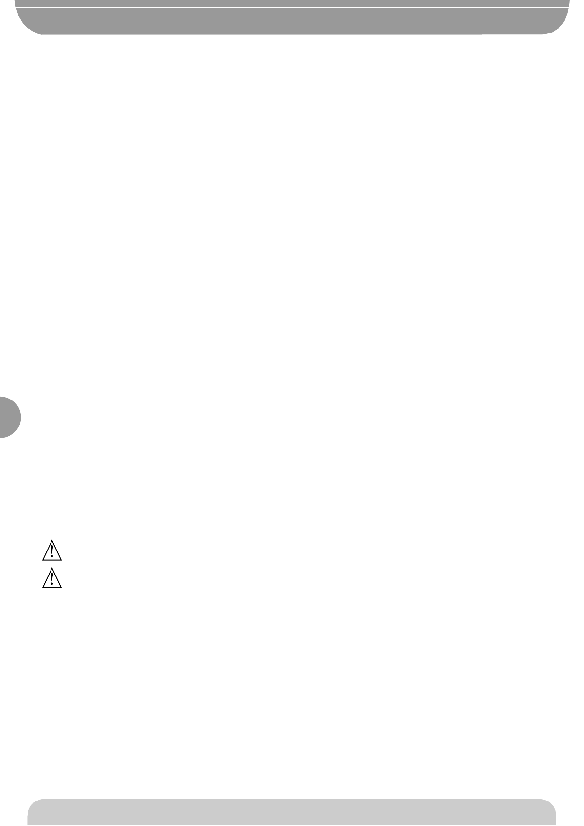
The LEO control panel is supplied by the manufacturer with standard
setting. Any alteration must be set by means of the incorporated display
programmer or by means of UNIPRO. The Control unit completely supports
the EELINK protocol, including the programmer self-supply from the control
unit.
It is available in two versions: one for external installation, inside the SD
box, the other fitted and pre-wired inside the ICARO controller.
Its main characteristics are:
- Electronic torque setting
- Adjustable electrodynamic braking
- Closing / opening limit-switch inputs
- Separate inputs for safety devices
- Clock input
- Serial protocol connection input
- Incorporated radio receiver
The board is provided with a terminal board which can be pulled out for
easier maintenance or replacement. The board is supplied with a series of
pre-wired jumpers to facilitate the installer’s work.
The jumpers relate to the following terminals: 21-23, 21-24 and 21-30. If the
above-mentioned terminals are in use, remove their respective jumpers.
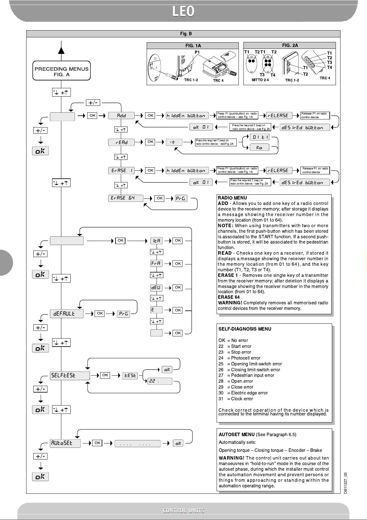
3) TECHNICAL SPECIFICATIONS
Power supply: ................................................................ 230V±10% 50Hz*
Mains/low voltage insulation: ....................................... > 2MOhm 500Vdc
Dielectric strength: ..................... mains/low voltage 3750Vac for 1 minute
Motor output current: .................................................................... 1.5Amax
Maximum motor power: ................................................................... 750W
Supply to accessories: ................................... 24Vac (1A max absorption)
Gate-open warning light: ................................................... 24Vac 3W max
Blinker: ............................................................................... 230V 40W max
Dimensions: ............................................................................. see figure 1
Fuses: ...................................................................................... see figure 2
(* other voltages available on request)
4) TERMINAL BOARD CONNECTIONS (Fig.3)
WARNING –During the wiring and installation operations, refer to the
current standards as well as principles of good technical practice.
The cables must be tied by additional fastening next to the terminals, by
means of clips for example.
All the operator wiring operations must be carried out by qualified personnel.
JP1
1
GND terminal
2-3 Single-phase mains supply 230V±10% 50Hz (2=N) (3=L)
JP2
4-5 Blinker connection (mains voltage) 40W Max.
6-7-8-9 Motor connection:
6 operation 1 + capacitor
7 common (blue)
8 operation 2
9 capacitor
JP3
10-11 Output 24V~ 1A max –power supply for photocells or other
devices.
12-13 Gate-open warning light output (24V 3W max)
JP5 Encoder connection
WARNING! The maximum length of the connection cable of
the encoder should not exceed 3.00 mt.
JP8
21-22 Open-Close button (N.O. Start), key selector.
21-23 Block button (N.C. Stop). If not used, leave jumped.
21-24 Photocell input (N.C.). If not used, leave jumped.
21-25 Opening limit switch connection (N.C. SWO). If not used,
leave jumped.
21-26 Closing limit switch connection (N.C. SWC). If not used, leave
jumped.
21-27 Pedestrian button connection (N.O. Ped)
21-28 Open-Button connection (N.O. Open)
21-29 Close-Button connection (N.O. Close)
21-30 Rubber edge connection (N.C.). If not used, leave jumped.
21-31 Timer input connection (N.O.). If the contact is open the leaves
close and the gate is ready for normal operation. If the contact
is closed (N.C.), the leaves open and remain open until the
contact is opened.
JP9
34 TX1 serial output
35 TX2 serial output
36 RX1 serial imput
37 RX2 serial input
38-39 Antenna input for snap-in radio receiver board (38 signal - 39
braid). Cable RG58
40-41 Second radio channel output of twin-channel receiver board
D811327_03
CONTROL UNITS
CONTROL UNITS

347
5) PROGRAMMING
The control panel provided with a microprocessor is supplied with function
parameters preset by the manufacturer, suitable for standard installations.
The predefined parameters can be altered by means of either the
incorporated display programmer or UNIPRO.
In the case where programming is carried out by means of UNIPRO,
carefully read the instructions relating to UNIPRO, and proceed in the
following way.
Connect the UNIPRO programmer to the control unit through the UNIFLAT
accessory (See fig. 5). Enter the “CONTROL UNITS”menu, and the
“PARAMETERS”submenu, then scroll the display screenfuls using the up/
down arrows, and set the numerical values of the parameters listed below.
For the function logics, refer to the “LOGIC”submenu.
In the case where programming is carried out by means of the incorporated
programmer, refer to Fig. A and B and to the “configuration”paragraph.
6) CONFIGURATION
The display programmer is used to set all the LEO control panel functions.
The programmer is provided with three pushbuttons for menu scrolling and
function parameter configurations (Fig. 2):
+ menu scrolling/value increment key
- menu scrolling/value reduction key
OK Enter (confirm) key
The simultaneous pressure of the + and –keys is used to exit the active
menu and move to the preceding menu.
If the + and –keys are pressed simultaneously at the main menu level
(parameters,logics,radio,language, autosetting,self-diagnosis),programming
is exited and the display is switched off (the OK message is displayed).
The modifications made are only set if the OK key is subsequently pressed.
When the OK key is pressed for the first time, the programming mode is
entered.
The following pieces of information appear on the display at first:
- Display Software version
- Control unit Software version
- Number of total manoeuvres carried out (the value is expressed in
thousands, therefore the display constantly shows 0000 during the first
thousand manoeuvres)
- Number of manoeuvres carried out since the latest maintenance operation
(the value is expressed in thousands, therefore the display constantly
shows 0000 during the first thousand manoeuvres)
- Number of memorised radio control devices.
When the OK key is pressed during the initial presentation phase, the first
menu (parameters) can be accessed directly.
Here follows a list of the main menus and the respective submenus
available.
The predefined parameter is shown between square brackets [ 0 ].
The writing appearing on the display is indicated between round brackets.
Refer to Figures A and B for the control unit configuration procedure.
6.1) Parameter Menu (PARAM)
1- Pedestrian opening (Mt. ped) [ 001.0 m ]
Set the numerical value of the pedestrian opening from 10 cm (000.1)
to 6m (006.0).
2- Automatic Closing Time (TCA) (tca) [ 40s ]
Set the numerical value of the automatic closing time from 1 to 180
seconds.
3- Encoder (Encoder) [ 80 ]
Set the encoder sensitivity value from 1 to 99. A higher value corresponds
to greater sensitivity, whereas a lower value corresponds to lesser
sensitivity.
WARNING: Check that the impact force value measured at the
points established by the EN 12445 standard is lower than that
specified in the EN 12453 standard.
Incorrect sensitivity setting can cause injuries to persons or
animals, or damage to things.
4- Opening torque (open torque) [ 50% ]
Set the motor opening torque value between 1% and 99%.
5- Closing torque (cls. torque) [ 50% ]
Set the motor closing torque value between 1% and 99%.
6- Brake (Brake) [ 0% ]
Set the required brake value between 0 and 99%, compatibly with the
weight of the gate and the existing stresses.
7- Zone (zone) [ 0 ]
Set the zone number between a minimum value of 0 and a maximum
value of 127. See paragraph 7 on “Serial connection”.
6.2) Logic Menu (lo ic.)
- TCA ( tca ) [ ON ]
ON Activates automatic closing
OFF Excludes automatic closing
- 3 Steps (3 step) [ OFF ]
ON Enables 3-step logic. A start impulse has the following effects:
door closed: ............................................................................ opens
on opening: ............................ stops and enters TCA (if configured)
door open: .............................................................................. closes
on closing: ....................................... stops and reverses movement
after stopping: ......................................................................... opens
OFF Disables 3-step logic
- Opening Impulse lock (Ibl open) [ OFF ]
ON The Start impulse has no effect during the opening phase.
OFF The Start impulse becomes effective during the opening phase.
- Impulse lock TCA (ibl TCA ) [ OFF ]
ON The Start impulse has no effect during the TCA dwell period.
OFF The Start impulse becomes effective during the TCA dwell period.
- Pre alarm (pre-alarM) [ OFF ]
ON The blinker comes on about 3 seconds before the motor starts.
OFF The blinker comes on at the same time as the motor starts.
- Hold-to-run (hold-to-run ) [ OFF ]
ON Hold-to-run operation: the manoeuvre continues as long as the
command key is kept pressed.
OFF Impulse operation: one impulse opens the gate if closed, and closes
it if open.
- Rapid closing (fast cls ) [ OFF ]
ON Closes the gate after photocell disengagement, before waiting for
the end of the TCA (automatic closing time) set.
OFF Command not entered.
- Photocells on opening (photc. open) [ OFF ]
ON: In case of obscuring, this excludes photocell operation on opening.
During the closing phase, it immediately reverses the motion.
OFF: In case of obscuring, the photocells are active both on opening and
on closing. When a photocell is obscured on closing, it reverses the
motion only after the photocell is disengaged.
- Master/Slave (Master) [ OFF ]
ON The control panel is set as Master in a centralised connection (see
Paragraph 7).
OFF The control panel is set as Slave in a centralised connection (see
Paragraph 7).
- Loop (loop) [ OFF ]
ON In the case of a closed loop centralised connection (Fig.5), set the
control unit to ON.
OFF In the case of an open centralised connection (Fig.5), set the control
unit to OFF.
6.3) Radio Menu (radio)
- Add (add)
Allows you to add one key of a radio control device to the receiver memory;
after storage it displays a message showing the transmitter number in the
memory location (from 01 to 64).
NOTE: When using transmitters with two or more channels, the first push-
button which has been stored is associated to the START function. If a
second push-button is stored, it will be associated to the pedestrian
function.
- Read (read)
Checks one key of a receiver; if stored it displays a message showing the
receiver number in the memory location (from 01 to 64), and the key number
(T1, T2, T3 or T4).
- Delete (erase 1)
Removes one single key of a transmitter from the receiver memory; after
deletion it displays a message showing the receiver number in the memory
location (from 01 to 64).
- Eliminate list (erase 64)
WARNING! Completely removes all memorised radio control devices from
the receiver memory.
6.4) Language Menu (Lan ua e)
Allows you to set the language on the display programmer.
5 languages are available:
- ITALIAN (TA)
- FRENCH (FRA)
- GERMAN (DEU)
- ENGLISH (ENG)
- SPANISH (ESP)
6.5) DEFAULT MENU (default)
Restores the preset default values on the control unit.
D811327_03
LEO
LEO
CONTROL UNITS
CONTROL UNITS

348
6.6) Self-diagnosis Menu (selftest)
Allows you to carry out control unit self-diagnosis.
If, at the end of the diagnosis, the answer is OK, it means that the control
unit and connected devices operate correctly.
In case of error, the display indicates the number of the terminal which does
not operate correctly; thus proceed to checking the devices connected to
this, making reference to the following table:
22 Start error
23 Stop error
24 Photocell error
25 Opening limit-switch error
26 Closing limit-switch error
27 Pedestrian input error
28 Open error
29 Close error
30 Electric edge error
31 Clock error
6.7) Autoset Menu (Autoset)
Allows you to automatically set the following parameters:
Opening torque
Closing torque
Encoder
Brake
To carry out autosetting, connect two N.O. pushbuttons, if not provided, to
inputs 21-28 (Open) and 21-29 (Close).
WARNING!! The autoset operation is only to be carried out after checking
the exact leaf (opening/closing) movement, and correct limit-switch
activation.
Therefore, during display of the (.... .... ....) message, carry out about fifteen
opening and closing manoeuvres in “Hold-to-run”mode, by pressing and
keeping the OPEN or CLOSE pushbutton alternatively pressed until the
opening or closing limit switches are activated.
During this phase, the control panel carries out tests with various levels of
opening/closing torque, encoder sensitivity and brake value.
Moreover, during autosetting, the leaf may be stopped, due to the checks
which are being carried out by the control panel.
After this, if autosetting is successfully completed, the control unit
automatically exits the (.... .... ....) phase, and displays the “OK”message
which indicates correct autoset execution.
If, on the other hand, the control unit remains in the (.... .... ....) phase after
the 15 expected manoeuvres, it means that there are certain resistance
points along the gate which do not allow the control unit to set optimum
operation values.
Proceed to find out whether there are any mechanical obstructions which
might prevent regular leaf movement.
WARNING! About 10 manoeuvres are carried out in “Hold-to-run”mode in
the course of the autoset phase, during which the installer must control the
automation movement and prevent persons or things from approaching or
standing within the automation working range.
WARNING: Check that the impact force value measured at the
points established by the EN 12445 standard is lower than that
specified in the EN 12453 standard.
Incorrect sensitivity setting can cause injuries to persons or
animals, or damage to things.
6.8) Statistics
Having connected the UNIPRO programmer to the control unit, enter the
CONTROL UNIT / STATISTICS menu and scroll the screenful showing the
statistical parameters:
- Board microprocessor software version.
- Number of cycles carried out. If motors are replaced, count the number
of manoeuvres carried out up to that time.
- Number of cycles carried out from the latest maintenance operation.
It is automatically set to zero after each self-diagnosis or parameter writing.
- Date of latest maintenance operation. To be updated manually from the
appropriate menu “Update maintenance date”.
- Installation description. 16 characters can be entered for installation
identification.
7) SERIAL CONNECTION (Fig.5)
The LEO control panel allows several automation units to be connected in
a centralised way by means of appropriate serial inputs and outputs. This
makes it possible to use one single command to open and close all the
automation units connected.
Following the diagram in Fig. 5, proceed to connecting all the LEO control
panels, exclusively using a telephone-type line.
Should a telephone cable with more than one pair be needed, it is
indispensable to use wires from the same pair.
The length of the telephone cable between one appliance and the next must
not exceed 250 m.
At this point, each of the LEO control panels must be appropriately
configured, by setting a MASTER unit first of all, which will have control over
all the others, to be necessarily set as SLAVE (see logic menu).
Also set the Zone number (see parameter menu) between 0 and 127.
The zone number allows you to create groups of automation units,
each one answering to the Zone Master unit. Each zone can only be
assigned one Master unit, the Master unit in zone 0 also controls the Slave
units in the other zones.
Loop closing of the serial connection (indicated by a dotted line in Fig.5) is
only needed if you require to check the no. of the connected devices by
means of UNIPRO.
7.1) Opposite sliding leaves (Fig. 6)
Serial connection also provides centralized control of two opposite
sliding gates (Fig. 6a).
In this case, the Master M1 control board will perform closing and opening
of Slave M2 control board simultaneously.
In case of opposite sliding leaves, the M1 (master) control board and the M2
(slave) control board should bear the same area number without other
devices being connected in such area.
If the opening direction of one of the two motors is incorrect, invert the
connection 6 and 8 of the motor as well as the connections 25 and 26 of
the opening and closing limiting devices.
The safety devices (photocells and sensing edges) should be connected
according to the diagram in Fig. 6b.
The Start, Open, Close, push-buttons and the Timer contact should be
normally connected to the M1 (master) control board.
The pedestrian command is to be connected to the M2 panel (slave).
The Stop command provides greater safety and is generated by a double
contact NC push-button connected to both control boards as shown in Fig. 6b.
NOTE: Disable the TCA function from the M2 (slave) panel.
8) SCRAPPING
Warning: This operation should only be carried out by qualified
personnel. Materials must be disposed of in conformity with the current
regulations. In case of scrapping, the automation devices do not entail any
particular risks or danger. In case of materials to be recycled, these should be
sorted out by type (electrical components, copper, aluminium, plastic etc.).
9) DISMANTLING
Warning: This operation should only be carried out by qualified
personnel. When the control unit is disassembled to be reassembled on
another site,proceed as follows:
•Disconnect the power supply and the entire electrical installation.
•In the case where some of the components cannot be removed or are
damaged, they must be replaced.
The descriptions and illustrations contained in the present manual
are not binding. The Company reserves the right to make any alterations
deemed appropriate for the technical, manufacturing and commercial
improvement of the product, while leaving the essential product
features unchanged, at any time and without undertaking to update
the present publication.
D811327_03
LEO
LEO
CONTROL UNITS
CONTROL UNITS

349
LEGENDA
Fig. A
OK
Press the OK key
BFT
Disp 1.0
LEO 1.0
0000
0000
00
PARAM.
LOGIC.
[
00
]
Parameter increment/reduction
or ON/OFF commutation
Menu scrolling
(+ = preceding - = following)
Press OK key (Enter/confirm)
OK! message (confirms modification made)
Mt.ped
PRG
PRG
[
001.0
]
ENCOder
OK
OK OK
OK
OK OK
OK OK
OK OK
OK OK
OK
OK
OK
OK
+
/
-
+
/
-
+
/
-
OK
brake
[
000
]
PRG
cls torque
[
050
]
PRG
open torque
[
050
]
PRG
[
080
]
PRG
TCA
[
040
]
PRG
ZONe
[
000
]
PRG
ACCESS TO MENUS
FOLLOWING MENUS
FIG. B
-+
/ON
/OFF
-+
-+
-+
-+
-+
-+
-+
-+
Display software version
Control unit software version
No. total manoeuvres
(in thousands)
No. manoeuvres since latest
maintenance(in thousands)
No. radio control devices
memorised
KO! message (value or function error)
PRG
ÒWaitÓ message (enter value or function)
OK
8888
PARAMETER MENU
Pedestrian opening
- value expressed in m
(default 001.0=1m, min 000.1=0,1m, max
006.0=6m)
TCA -
value expressed in seconds (default
40=40s, min 1=1s, max 180=180s)
Encoder
Ð value expressed in % (default
80%, min 1%, max 99%)
Opening torque
Ð value expressed in %
(default 50%, min 1%, max 99%)
Closing torque Ð
value expressed in %
(default 50%, min 0%, max 99%)
Brake Ð
value expressed in % (default 0%,
min 1%, max 99%)
Zone Ð
numerical value (default 0, min 0,
max 127)
+
/
-
Simultaneously press the + and - keys.
Simultaneous pressure of the + and Ð keys
allows you to exit the active menu and return
to the preceding menu; if this takes place at
the main menu level, programming is exited
and the display switched off.
The modifications made are only confirmed if
the OK key is subsequently pressed.
Preset value
PRG
OK
+
/
-
OK
-+
-+
-+
-+
-+
-+
-+
-+
-+
PRG
OK
PRG
OK
PRG
OK
PRG
OK
PRG
OK
PRG
OK
PRG
OK
PRG
OK
PRG
OK
OK
photoc. open
ON
OFF
[
off
]
OK
Mast
er
ON
OFF
[
off
]
OK
LOOP
ON
OFF
[
off
]
OK
fast cls
ON
OFF
[
off
]
OK
hold-to-run
ON
OFF
[
off
]
OK
PRE-ALarm
ON
OFF
[
off
]
OK
ibl
tca
ON
OFF
[
off
]
OK
ON
OFF
[
off
]
iblopen
OK
3 step
ON
OFF
[
off
]
OK
TCA
ON
OFF
[
on
]
D811327_03
LEO
LEO
CONTROL UNITS
CONTROL UNITS

350
Fig. B
22 . .. 31
lan ua e
P1
T1
T2
T1
T2
T3
T4
TRC 1-2 TRC 4
FIG. 1A FIG. 2A
TRC 1-2 TRC 4
MITTO 2-4
T1 T2 T1 T2
T3 T4
P1
RADIO
Press P1 (pushbutton) on radio
control device Ð see Fig. 1A
Press the required T (key) on
radio control device Ð see Fig. 2A
Press the required T (key) on
radio control device Ð see Fig. 2A
Release P1 on radio
control device
ADD hidden button release
desired button
01
erase 1
PRG.
read
SELF-DIAGNOSIS MENU
OK = No error
22 = Start error
23 = Stop error
24 = Photocell error
25 = Opening limit-switch error
26 = Closing limit-switch error
27 = Pedestrian input error
28 = Open error
29 = Close error
30 = Electric edge error
31 = Clock error
Check correct operation of the device which is
connected to the terminal having its number displayed.
AUTOSET MENU
(See Paragraph 6.5)
Automatically sets:
Opening torque Ð Closing torque Ð Encoder Ð Brake
WARNING!
The control unit carries out about ten
manoeuvres in Òhold-to-runÓ mode in the course of the
autoset phase, during which the installer must control
the automation movement and prevent persons or
things from approaching or standing within the
automation operating range.
RADIO MENU
ADD
- Allows you to add one key of a radio control
device to the receiver memory; after storage it displays
a message showing the receiver number in the
memory location (from 01 to 64).
NOTE:
When using transmitters with two or more
channels, the first push-button which has been stored
is associated to the START function. If a second push-
button is stored, it will be associated to the pedestrian
function.
READ
- Checks one key on a receiver, if stored it
displays a message showing the receiver number in
the memory location (from 01 to 64), and the key
number (T1, T2, T3 or T4).
ERASE 1
- Removes one single key of a transmitter
from the receiver memory; after deletion it displays a
message showing the receiver number in the memory
location (from 01 to 64).
ERASE 64
WARNING!
Completely removes all memorised radio
control devices from the receiver memory.
ITA
01
FRA
DEU
ENG
esp
PRECEDING MENUS
FIG. A
OK
OK
OK
Press P1 (pushbutton) on radio
control device Ð see Fig. 1A
Press the required T (key) on
radio control device Ð see Fig. 2A
Release P1 on radio
control device
hidden button release
desired button
OK
OK
OK OK
OK
OK
OK
OK
OK
OK
PRG
+
/
-
-+
-+
-+
-+
-+
. . . . . . . .
OK
AUTOset
selftest
test
ERASE 64
+
/
-
+
/
-
+
/
-
+
/
-
+
/
-
DEFAULT
-+
-+
-+
-+
-+
-+
-+
01 t1
D811327_03
LEO
LEO
CONTROL UNITS
CONTROL UNITS

351
Fig. 2
Fig. 3
Fig. 1
JP1 JP2
123
C
456789
21 22 23 24 25 26 27 28 29 30 31
L
N
GND
1
2
3
JP8
START
COM
NO NC NC NO NC NO NO NO NC NO
STOP
M
ANT.
SWC
PED
OPEN
CLOSE
TIMER
COSTA
II¡CH.R
24 V~
PHOT
SW0
10 11 12 13
JP3
ANT
SHIELD
24 V~
40W max.
34 35 36 37 38 39 40 41
JP9
4
5
6
7
8
9
21 22 23 24 25 26 27 28 29 30 31 34 35 36 37 38 39 40 41
+
OK Enter
8888
236
194
100
LEO
SD
8888
24V
3W max. SCA
TX1
RX1
RX2
TX2
Fig. 5
10
11
12
13
6,3 AF
0,315 AT
2AT
D811327_03
LEO
LEO
CONTROL UNITS
CONTROL UNITS

352
Fig. 4
Fig. 5
LEO
UNIPRO
TX1
RX1
RX2
TX2
TX1
RX1
RX2
TX2
TX1
RX1
RX2
TX2
TX1
RX1
RX2
TX2
Max. 250m
UNIFLAT
8888
21 22 23 24 25 26 27 28 29 30 31
34 35 36 37 38 39 40 41
21 22 23 24 25 26 27 28 29 30 31
34 35 36 37 38 39 40 41
21 22 23 24 25 26 27 28 29 30 31
34 35 36 37 38 39 40 41
21 22 23 24 25 26 27 28 29 30 31
34 35 36 37 38 39 40 41
D811327_03
LEO
LEO
CONTROL UNITS
CONTROL UNITS

353
Fig. 6
TX1
TX2
RX1
RX2
SWO1
SWC1
CC1
TX1
RX1 CC1 CC2
TX2 RX2
1
2
3
4
5
6
7
8
9
21 22 23 24 25 26 27 28 29 30 31 34 35 36 37 38 39 40 41
10
11
12
13
5 AF
0,315 AT
2AT
M2
SLAVE
M1
MASTER
FIG. 6a
FIG. 6b
LEO
M1 (MASTER)
1
2
3
4
5
6
7
8
9
21 22 23 24 25 26 27 28 29 30 31 34 35 36 37 38 39 40 41
10
11
12
13
5 AF
0,315 AT
2AT
LEO
M2 (SLAVE)
TCA OFF
STOP
SWO2
SWC2
CC2
NC
PHOT
NC
NC
NC
NC NC NC
D811327_03
LEO
LEO
CONTROL UNITS
CONTROL UNITS
Table of contents
Other BFT Control Unit manuals