BFT CAPRI User manual

CAPRI
D811282 26-03-02 Vers. 03
CONTROL UNIT

373
CAPRI
CAPRI
CONTROL UNITS
CONTROL UNITS
D811282_03
Thank you for buying this product, our company is sure that you will be more
than satisfied with the performance of the product.
Read the “Instruction Manual”supplied with this product carefully, as it
provides important information about safety, installation, operation and
maintenance. This product complies with recognised technical standards
and safety regulations. We declare that this product is in conformity with the
following European Directives: 89/336/EEC (amended by RL 91/263/EEC,
92/31/EEC and 93/68/EEC), 73/23/EEC, 99/5/EEC.
1) GENERAL OUTLINE
Capri is a control unit especially designed for tubular motors controlling
roller shutters and sunblinds and is compatible with the EElink protocol. It
is available in the CAPRI and CAPRI RIC versions. Besides the functions
of mod. CAPRI, the control unit mod. CAPRI RIC provides the radio control
by means of the transmitters of the TRC series. Both models can be
equipped with additional attachments such as anemometers, twilight
sensors, solar cells and opening, closing and stop buttons. Furthermore, it
is possible to connect special safety devices when necessary.
The commands can also be sent by radio by means of a transmitter of the
rolling code series. Memorization on the transmitters is obtained based on
the self-learning method. The unit provides a centralized wire control
system that can be subdivided into 8 or more zones regardless of the wiring.
2) GENERAL SAFETY
WARNING! An incorrect installation or improper use of the product
can cause damage to persons, animals or things.
•The “Warnings”leaflet and “Instruction booklet”supplied with this
product should be read carefully as they provide important information
about safety, installation, use and maintenance.
•Scrap packing materials (plastic, cardboard, polystyrene etc) according
to the provisions set out by current standards. Keep nylon or polystyrene
bags out of children’s reach.
•Keep the instructions together with the technical brochure for future
reference.
•This product was exclusively designed and manufactured for the use
specified in the present documentation. Any other use not specified in
this documentation could damage the product and be dangerous.
•The Company declines all responsibility for any consequences resulting
from improper use of the product, or use which is different from that
expected and specified in the present documentation.
•Do not install the product in explosive atmosphere.
•The Company declines all responsibility for any consequences resulting
from failure to observe Good Technical Practice when constructing
closing structures (door, gates etc.), as well as from any deformation
which might occur during use.
•The installation must comply with the provisions set out by the following
European Directives: 89/336/EEC, 73/23/EEC, 98/37/ECC and
subsequent amendments.
•Disconnect the electrical power supply before carrying out any work on
the installation. Also disconnect any buffer batteries, if fitted.
•Fit an omnipolar or magnetothermal switch on the mains power supply,
having a contact opening distance equal to or greater than 3mm.
•Check that a differential switch with a 0.03A threshold is fitted just
before the power supply mains.
•Check that earthing is carried out correctly: connect all metal parts for
closure (doors, gates etc.) and all system components provided with an
earth terminal.
•The Company declines all responsibility with respect to the automation
safety and correct operation when other manufacturers’components
are used.
•Only use original parts for any maintenance or repair operation.
•Do not modify the automation components, unless explicitly authorised
by the company.
•Instruct the product user about the control systems provided and the
manual opening operation in case of emergency.
•Do not allow persons or children to remain in the automation
operation area.
•Keep radio control or other control devices out of children’s reach, in
order to avoid unintentional automation activation.
•The user must avoid any attempt to carry out work or repair on the
automation system, and always request the assistance of qualified
personnel.
•Anything which is not expressly provided for in the present instructions,
is not allowed.
3) TECHINCAL SPECIFICATIONS
Mains power supply: ..................................................230Vac ±10%, 50Hz
Motor current: .........................................................................................2A
Motor power: ......................................................................................350W
Number of storable radio-controls: ........................................................ 64
Reception frequency (CAPRI RIC only):................................. 433.92MHz
Current for external attachments: .................................................... 70mA
Number of zones with wire control (master): ................................8 or 127
Max. connection length: .................................................................... 250m
Protection degree of case: .............................................................IP20 (*)
Dimensions: ............................................................................. see figure 1
Weight: .................................................................................... 350g approx
(*) The protection degree of the enclosure is brought to IP55 by applying a
special accessory supplied on request. Only use fittings suited to the
container dimensions and cable diameter.
4) INSTALLATION
The unit is usually installed inside the shutter box as shown in figure 2; in
case of blinds, the unit should possibly be installed in a dry and sheltered
place. Always choose a position, which grants access to the shutter or blind
when these are completely rolled up or unrolled. When selecting the
installation position, also consider the availability of a connector block in the
electric installation or the possibility of installing visible or hidden pipes.
Make some openings in which to pass the cables and use the cable-holders
or the PG9 joints supplied depending on the protection degree to be
reached with the case, and based on the installation conditions.
Fasten the support (fig.3) marking the two holes by using the two slots
provided on the container as a template. Use the screws supplied directly
or make a 4mm hole to insert the anchors supplied depending on the
material the support is made of. Tighten the screws completely and correct
any centering difference using the slots on the container.
NOTE: when drilling or tightening the screws, be careful not to
damage the ducts or the cables underneath.
The sensors must be installed so as they can detect the operating
conditions of the corresponding devices: the anemometer should be place
in a position where the conditions are the same as for the shade and the
twilight sensor should be place in a sufficiently lit position.
5) ELECTRICAL CONNECTIONS
CAUTION:The electrical connections must be workmanlike performed
only by qualified and specialized technicians who also have to
observe any current directives and use suitable materials.
A knife switch must be installed before the appliance, with an opening
distance between the contacts equal to or greater than 3 mm, with
magnetothermal and differential protection having a capacity suited to the
consumption of the appliance.
Only use cables in compliance with harmonized or national standards for
wiring, with a section appropriate for the protections located upstream, the
consumption and the installation conditions.
Connect the accessories, safety and control devices to the motor unit,
making sure that the mains voltage connections are kept totally separate
from the low voltage accessory connections. Make reference to figure 4 for
the single system connection or to figure 5 for the connection of the units
of a centralized system.To ensure continuity of the ground protection
circuit, connect the earth wire of the operator to the earth wire of the
power supply unit using the terminal supplied. The serial connections
to obtain a centralized wire control must only be made using telephone-type
pair. When using a telephone wire with several pairs it is necessary to use
the wires of the same pair. The length of the telephone wire between the
unitsmust not exceed 250m. The control push-buttons should be provided
with symbols indicating the actual operation direction (fig.6).
If other devices have to be connected onto the STOP and PHOTOCELL
terminals, it is necessary to remove the jumpers connected by the
manufacturer. When connecting several devices to one of these
inputs, they must be connected in series.
6) WIRE CONTROL
To obtain a local wire control, it is sufficient to connect the inputs of the
board according to the instructions given in paragraph 4 and fig.4.
If a centralized wire control has to be obtained, it is necessary to carry out
the connections of fig.5 following the instructions given in paragraph 4 in
addition to the connections described above. Furthermore, it is necessary
to identify the master board and set the zone addresses. The master board
is the one in which all the controls are carried out by all the other boards
belonging to the same zone. To configurate the board as a master board,
move the DIP switch 5 to “ON”. Only one master board can be identified in
each zone. The zone includes all the boards with the same address; the
address is set by mean of the three DIP switches n°6, 7, 8.
Therefore, it is possible to define up to 8 different zones regardless of the
wiring.
A master device having the zone configuration set to value 0 controls all the

374
D811282_03
CONTROL UNITS
CONTROL UNITS
CAPRI
CAPRI
other connected devices (overall control), regardless of their configuration
(master or slave).If a system requires more than 8 zones, it is possible to
define different addresses from 8 to 127 using the UNIPRO universal
programmer and setting the number of the zone in the advanced parameter
“Address 1”. In this case, the address programmed using the UNIPRO will
prevail over the one programmed using the DIP switches. To return to the
configuration function using the dip switches, set the advanced parameter
“Address 1”to 0, using the UNIPRO, or erase the memory completely as
described below (in this case all information stored in the board will be
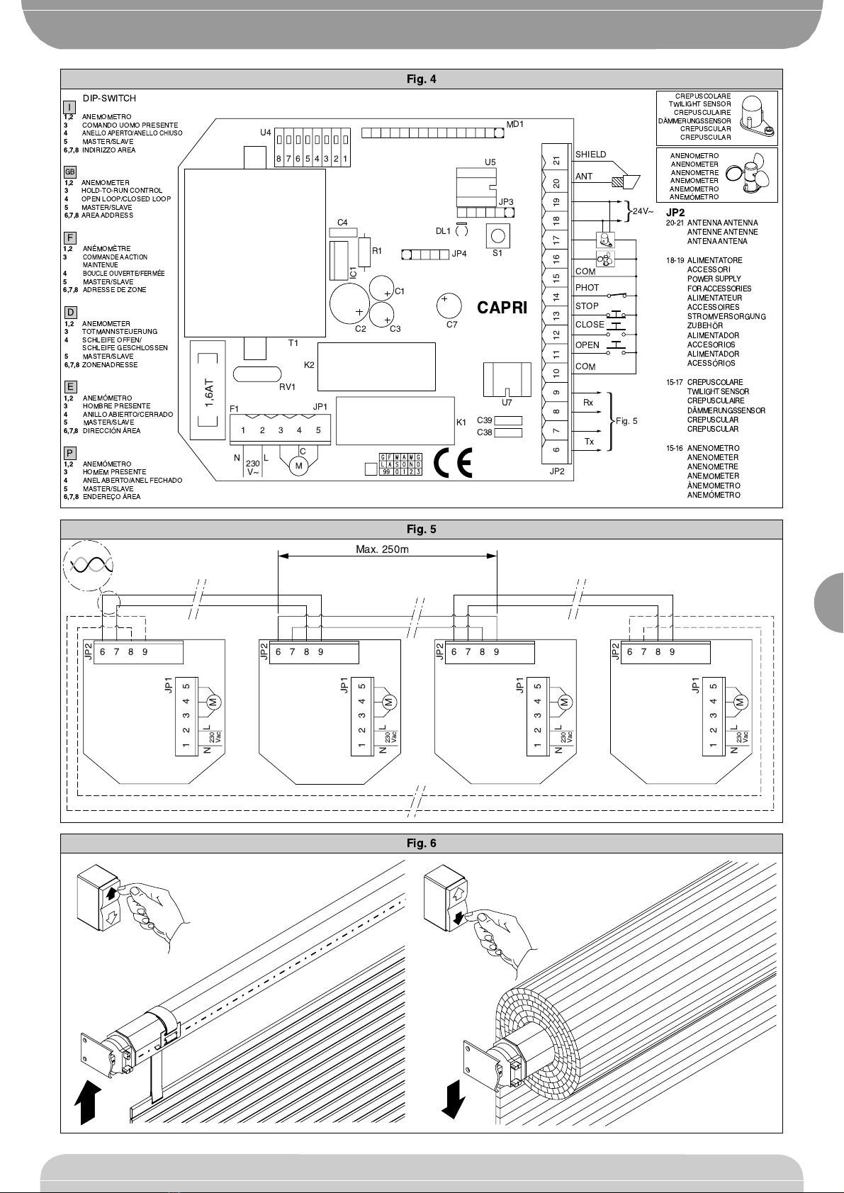
erased). A centralized wire system can be created both by closing the loop
(carrying out the connections marked with a broken line in fig.5 and setting
to ON the dip switch n°4 of the master boards), or by leaving the loop open
(without carrying out the connections marked with a broken line in fig.5 and
leaving on OFF the dip switch n°4 of all boards).
When the loop is closed, each zone master checks the execution of the
commands by the slave boards and updates a part of the statistics relating
to the loop composition. The unsuccessful commands will be repeated after
a few minutes. When the loop is open, these operations are not possible
while all the other functions remain unaltered. The panels preset for radio
control can also be connected via wire. In this case, and when they are
defined as master, or overall control master devices, only the centralised
radio controls related to the T2, T3 and T4 keys (stop, open and close) are
sent via cable, whereas the T1 key (four-step logic) operates locally and is
not sent via cable.
NOTE: The maximum number of devices, including master and slave
types, which can be connected to an individual network, is equal to 255,
consequently a master panel can control up to a maximum of 254 slave
panels.
In the case of installations with a high number of slave panels, the
transmission delay of a command sent by the master to the subsequent
slave device is about 0.5s. Therefore, to give an example, the 50th slave
panel on the line will have a delay in executing the command of about 25s
with respect to the master panel.
7) ANEMOMETER CONFIGURATION
The anemometer can be connected as described in paragraph 4 (fig.4) to
obtain the automatic closure when the wind speed is greater than a certain
preset threshold. The threshold causing the anemometer to step in is set by
using the DIP switches n°1 and 2. The table given below shows the
approximate speed of the wind corresponding to the threshold relating to
theaccessory P111182 (anemometer performing 2impulses per revolution):
Dip n°1 Dip n°2Threshold Hz m/s km/h
OFF OFF 11,5 4,2 15
OFF
ON
ON
ON
OFF
ON
23
35
47
8,4
12,6
16,8
30
45
60
The control of the anemometer on the master board acts in a
centralized way, while the controls of the anemometer on the slave
boards act locally.
8) TWILIGHT SWITCH
It is possible to connect a twilight switch (see paragraph and fig.4).
The closure of the twilight switch contact originates a closing command in
the actuator. When the contact re-opens, it originates an opening command
in the actuator. The twilight control of the master board acts in a centralized
way, while the twilight commands of the slave boards only act locally.
9) SAFETY DEVICE
In case of automatic or semi-automatic control, it is possible to connect a
safety device (see paragraph and fig.4) as may be prescribed by the safety
standards. The opening of the contact during the closing phase originates
an opening command. Such a command only acts locally.
The safety device can be supplied with 24Vac power from the terminals 19
and 20 (max 70mA).
10) HOLD-TO-RUN CONTROLS
By setting to ON the dip Switch n°3 the input controls of the board become
hold-to-run controls. In this case, the functions of the receiver and external
sensors are inhibited. In case of a centralized wire system, the command
originated by the serial network are not processed.
11) RADIO CONTROL (FOR MOD. CAPRI RIC ONLY)
The radio-controls combined with the CAPRI RIC control board, can
feature 1, 2 or 4 keys. The functions of each key are the following:
Key 1: local control with 4-step logic (the first impulse opens, the second
impulse stops on opening, the third impulse closes, the fourth
stops on closing).
Key 2: local and zone stop control.
Key 3: local and zone opening control.
Key 4: local and zone closing control.
11.1) MANUAL PROGRAMMING OF RECEIVER
For receiver programming, press the key S1 located on the Capri board, the
LED DL1 will flash with a frequency of 2Hz to confirm that the transmitters
are operating in the self-learning mode. Press the key hidden by the
transmitters with 1 or 2 keys (see fig.8) within 10 seconds or jump the 4-key
transmitters (see fig.8). The LED DL1 will stay on permanently. Press the
correct key of the transmitter within 10 seconds. When selecting the key,
bear in mind that if the key 1 is pressed after pressing the hidden key, all
the keys of the transmitter are stored in the receiver. If the key 2 is pressed,
the keys 2, 3, 4 will be stored. If the keys of the transmitters are stored
correctly on the different receivers, a centralized system can be obtained
without connecting the control boards to one another. To this purpose, use
single-channel or double-channel transmitters for local commands or four-
channel transmitters for centralized commands. An example is given in
figure 7: the TX1 has been stored using the key 1 on the CAPRI 1 control
unit and using the key 2 on the CAPRI 2 and CAPRI 3 control units.
Furthermore, the transmitter TX2 has been stored in CAPRI 2 control unit
using the key 1 while the transmitter TX3 has been stored in the CAPRI 3
control unit always using the key T1. Under these circumstances, the key
T1 of the transmitter TX1 will control the motor M1 based on the 4-step logic
M1 (local control) and the keys T2,T3 and T4 of the transmitter TX1 will
control stopping, opening and closing of all the 3 motors respectively
(centralized control). The transmitters TX2 and TX3, on the other hand,
perform a local command with 4-step logic onto M2 and M3 respectively.
By repeating the method, it is possible to perform the centralized control of
several zones with great flexibility as far as activation and subdivision are
concerned. Obviously, with this type of centralized control, the commands
sent by wire (opening, closing, stop, photocell, twilight sensor, anemometer
metro) will only be of local nature.
11.2) RADIO PROGRAMMING OF RECEIVER
After manual programming of the first radio-control, it is possible to perform
a radio programming (without having to operate on the control unit again).
To start this programming mode, press the hidden key of a transmitter
already programmed and then press a key on the same transmitter within
10 seconds. In this way, the transmitter operated by the control unit will
switch to self-learning mode and it will be possible to execute all the steps
described for the manual programming of the receiver.
11.3) PROGRAMMING OFTHERECEIVERUSING THEEELINKPROTOCOL
The receiver can also be programmed using the EElinkprotocol, connecting
the UNIPRO terminal by means of the UNIFLAT and UNIDA accessories.
Before connecting the UNIDA accessory to the board, remove the jumper
J1. Upon completion of cancellation, remember to reposition the jumper J1
on pin 1 and 2 of the connector JP3, otherwise the parameters stored in the
board will not be protected from accidental overwriting. The arrangement
of the connections is shown in fig. 8. When programming the receiver make
reference to the instructions for the UNIPRO terminal. Up to 64 radio-
controls can be stored and the control unit can control both standard and
personalized radio-controls. As far as the arrangement of the outputs is
concerned, the control unit CAPRI acts as a 4-channel receiver in which the
outputs have the following functions regardless of the mode programmed:
Output 1: local control with 4-step logic (the first impulse opens, the
second impulse stops on opening, the third impulse closes,
the fourth stops on closing).
Output 2: local and zone stop control.
Output 3: local and zone opening control.
Output 4: local and zone closing control.
The control unit CAPRI does not supply power to the programming
terminal. For transmitter personalization, use the UNITRC and UNIFLAT
accessories and follow the instructions supplied with the programmer.
Note: the personalization of a transmitter acts in an irreversible way
on the code stored therein. The personalized code can be changed but
the transmitter cannot be configurated as standard again.
12) ERASURE OF STORAGE
To erase the storage of the board, move the jumper J1 on pin 2 and 3 of
connector JP3, press the key S1 for 10 seconds. The LED DL1 flashes with
a frequency of 5Hz and then stays on permanently for a few seconds until
the storage has been erased. This operation will erase all data from the
board memory, and its configuration will be the same as the original one set
by the manufacturer. Upon completion of cancellation, remember to

375
CAPRI
CAPRI
CONTROL UNITS
CONTROL UNITS
D811282_03
reposition the jumper J1 on pin 1 and 2 of the connector JP3 otherwise the
parameters stored in the board will not be protected from accidental
overwriting.
13) STATISTICS
By connecting a programmer compatible with the EElink protocol it is
possible to read some statistical parameters of the system such as:
Board version: indicates the name and version of the board.
List description: indicates the description assigned to the system.
This description can be inserted ormodified by means of the UNIPRO terminal.
Number of manoeuvres: indicates the number of manoeuvres that the
board has performed since its installation.
Number of manoeuvres since maintenance: indicates the number of
manoeuvres performed since last maintenance operation, including any
configuration operation of the board and self-diagnosis.
Maintenance date: indicates the date of the last maintenance
operation performed.
Maintenance updating: allows the number of manoeuvres to be updated
since last maintenance operation.
Zoneexecutors (advancedstatistics) “Address16”:indicatesthe number
of the actuators belonging to the same master zone (it is updated by the
master boards only).
Total executors “Configuration 17”:indicates the total quantity of the
actuators connected (it is updated by the master boards only).
14) SELF-DIAGNOSIS
The board features a luminous diode DL1 which indicates the current state
according to the table given below:
On Leds Diagnosis
DL1 Off or On for more than 10s Microprocessor fault.
DL1 On for less than 10s Key in stand-by for storage of a
radio-control or erasure of storage.
DL1 1Hz flashing Activeboard in stand-byor command
execution.
DL1 2Hz flashing Activation of code storage
DL1 5Hz flashing Activation of total storage erasure.
DL1 10Hz flashing Transmitter reception in course.
Besides the signals given by the LED, the CAPRI board provides the self-
diagnosis functions offered by the EElink protocol. When performing the
self-diagnosis by means of the UNIPRO terminal it is possible to obtain a
diagnostic message identifying the active inputs, that is the ones in a state
different from the stand-by position.
The stand-by position is defined as a condition in which no control signals
are active and no safety devices have stepped in.
15) MAINTENANCE AND DEMOLITION
The maintenance of the system should only be carried out by qualified
personnel regularly. The materials making up the set and its packing must
be disposed of according to the regulations in force.
Batteries must be properly disposed of.
16) SUMMARY OF DIP-SWITCH FUNCTIONS
The control unit comprises 8 dip-switches, which allow to select the
operation modes according to the table given below:
n°DIP Description
1,2 Anemometer See paragraph 6
3 Hold-to-run control ON: The opening and closing
controls are hold-to-run type and
onlylocal. The operation of the serial
unit and the radio functions receiver
are not included.
OFF: The opening and closing
controls are semi-automatic and all
configurated are operative.
4 Open/closed loop ON: The connections marked with a
(for master boards broken line in fig.5 have been made,
only, leave Off for the advanced statistics are being
slave boards) managed.
OFF: The connections marked with
a broken line in fig.5 have not been
made, the advanced statistics are
not being managed.
5 Master / Slave ON: The board sends global and
zone commands to the telephone
pair
OFF: The board performs the global
and zone commands received by
the telephone pair.
6,7,8 Zone address 0=OFF, 1=ON
0,0,0 All system
0,0,1 Zone 1
0,1,0 Zone 2
0,1,1 Zone 3
1,0,0 Zone 4
1,0,1 Zone 5
1,1,0 Zone 6
1,1,1 Zone 7
The descriptions and illustrations contained in the present manual
arenot binding. The Company reserves the rightto makeany alterations
deemed appropriate for the technical, manufacturing and commercial
improvement of the product, while leaving the essential product
features unchanged, at any time and without undertaking to update
the present publication.

376
D811282_03
CONTROL UNITS
CONTROL UNITS
CAPRI
CAPRI
Fig. 2
Fig. 1
Fig. 3
110
147
34
S1
U4
DL1
JP3

377
CAPRI
CAPRI
CONTROL UNITS
CONTROL UNITS
D811282_03
Fig. 5
Fig. 4
Fig. 6
JP1
1
876
2345
NL M
230
Vac
JP2
JP1
12345
NL M
230
Vac
JP2
JP1
12345
NL M
230
Vac
JP2
JP1
12345
NL M
230
Vac
JP2
Max. 250m
9 876 9 876 9 876 9
ANENOMETRO
ANENOMETER
ANENOMETRE
ANEMOMETER
ANEMOMETRO
ANEMîMETRO
CREPUSCOLARE
TWILIGHT SENSOR
CREPUSCULAIRE
DMMERUNGSSENSOR
CREPUSCULAR
CREPUSCULAR
P
1,2
ANEMîMETRO
3
HOMEM PRESENTE
4
ANEL ABERTO/ANEL FECHADO
5
MASTER/SLAVE
6,7,8
ENDEREO çREA
I
1,2
ANEMOMETRO
3
COMANDO UOMO PRESENTE
4
ANELLO APERTO/ANELLO CHIUSO
5
MASTER/SLAVE
6,7,8
INDIRIZZO AREA
GB
1,2
ANEMOMETER
3
HOLD-TO-RUN CONTROL
4
OPEN LOOP/CLOSED LOOP
5
MASTER/SLAVE
6,7,8
AREA ADDRESS
F
1,2
ANMOMéTRE
3
COMMANDE A ACTION
MAINTENUE
4
BOUCLE OUVERTE/FERME
5
MASTER/SLAVE
6,7,8
ADRESSE DE ZONE
D
1,2
ANEMOMETER
3
TOTMANNSTEUERUNG
4
SCHLEIFE OFFEN/
SCHLEIFE GESCHLOSSEN
5
MASTER/SLAVE
6,7,8
ZONENADRESSE
E
1,2
ANEMîMETRO
3
HOMBRE PRESENTE
4
ANILLO ABIERTO/CERRADO
5
MASTER/SLAVE
6,7,8
DIRECCIîN çREA
JP2
20-21 ANTENNA ANTENNA
ANTENNE ANTENNE
ANTENA ANTENA
18-19 ALIMENTATORE
ACCESSORI
POWER SUPPLY
FOR ACCESSORIES
ALIMENTATEUR
ACCESSOIRES
STROMVERSORGUNG
ZUBEHR
ALIMENTADOR
ACCESORIOS
ALIMENTADOR
ACESSîRIOS
15-17 CREPUSCOLARE
TWILIGHT SENSOR
CREPUSCULAIRE
DMMERUNGSSENSOR
CREPUSCULAR
CREPUSCULAR
15-16 ANENOMETRO
ANENOMETER
ANENOMETRE
ANEMOMETER
ËNEMOMETRO
ANEMîMETRO
DIP-SWITCH
T1
C4
C2 C3
C1
IC1
R1
U5
U4
JP3
K1 C39
C38
RV1
JP1
1,6AT
1
6 7 8 9 10 11 12 13 14 15 16 17 18 19 20 21
2345
F1
NL C
M
S1
U7
K2
MD1
24V~
SHIELD
ANT
Tx
Rx
Fig. 5
230
V~ JP2
12345678
DL1
C7
JP4
CAPRI
COM
PHOT
STOP
CLOSE
OPEN
COM

378
D811282_03
CONTROL UNITS
CONTROL UNITS
CAPRI
CAPRI
Fig. 7
Fig. 8
UNIDA
UNIFLAT
UNITRC
UNITRC
UNIFLAT
UNIPRO
UNIFLAT
TRC1-2-4
CAPRI
J1
JP1
CAPRI 1
TX1
M1
1
181920
2345
NL
230
Vac
JP2
TRC4
T1
T2
T3
T4
JP1
CAPRI 2
TX2
M2
1
181920
2345
NL
230
Vac
JP2
TRC4
T1
T2
T3
T4
JP1
CAPRI 3
TX3
M3
1
181920
2345
NL
230
Vac
JP2
TRC4
T1
T2
T3
T4
CONNETTORE JP3 ¥ CONNECTOR JP3
CONNECTEUR JP3 ¥ STECKVERBINDER JP3
CONECTOR JP3 ¥ CONECTOR JP3
CONTATTI ¥ CONTACTS
CONTACTS ¥ KONTAKTE
CONTACTOS ¥ CONTACTOS
CONTATTI ¥ CONTACTS
CONTACTS ¥ KONTAKTE
CONTACTOS ¥ CONTACTOS
This manual suits for next models
1
Table of contents
Other BFT Control Unit manuals

BFT
BFT RIGEL 5 User manual

BFT
BFT ME BT User manual

BFT
BFT B EBA RS 485 LINK User manual

BFT
BFT Sirio TN1 User manual

BFT
BFT PERSEO CBE User manual

BFT
BFT MOOVI BT 30 User manual

BFT
BFT LIBRA C MA Installation and operating instructions

BFT
BFT SIRIO FR-TMA User manual

BFT
BFT MOOVI 30 User manual

BFT
BFT BOX User manual