10 -
SIRIO FR - TMA - Ver. 09
D811231 0001_09
MANUALE PER L’INSTALLAZIONE
ITALIANO
Nel ringraziarVi per la preferenza accordata a questo prodotto, la ditta è
certa che da esso otterrete le prestazioni necessarie al Vostro uso. Leggete
attentamente l’opuscolo ”Libretto istruzioni” che lo accompagna in quan-
to esso fornisce importanti indicazioni riguardanti la sicurezza, l’installazio-
ne, l’uso e la manutenzione. Questo prodotto risponde alle norme ricono-
sciute della tecnica e delle disposizioni relative alla sicurezza.Confermiamo
che è conforme alle seguenti direttive europee: 89/336/CEE, 73/23/CEE,
98/37/CE (e loro modifiche successive), applicando le seguenti norme
tecniche EN60335-1, PrEN12453, PrEN12445.
AVVERTENZE
Nelle operazioni di cablaggio ed installazione riferirsi alle norme vigenti e
comunque ai principi di buona tecnica.
AVVERTENZE
Qualunque intervento sui componenti dell’automazione deve essere ese-
guito da personale qualificato (installatore).
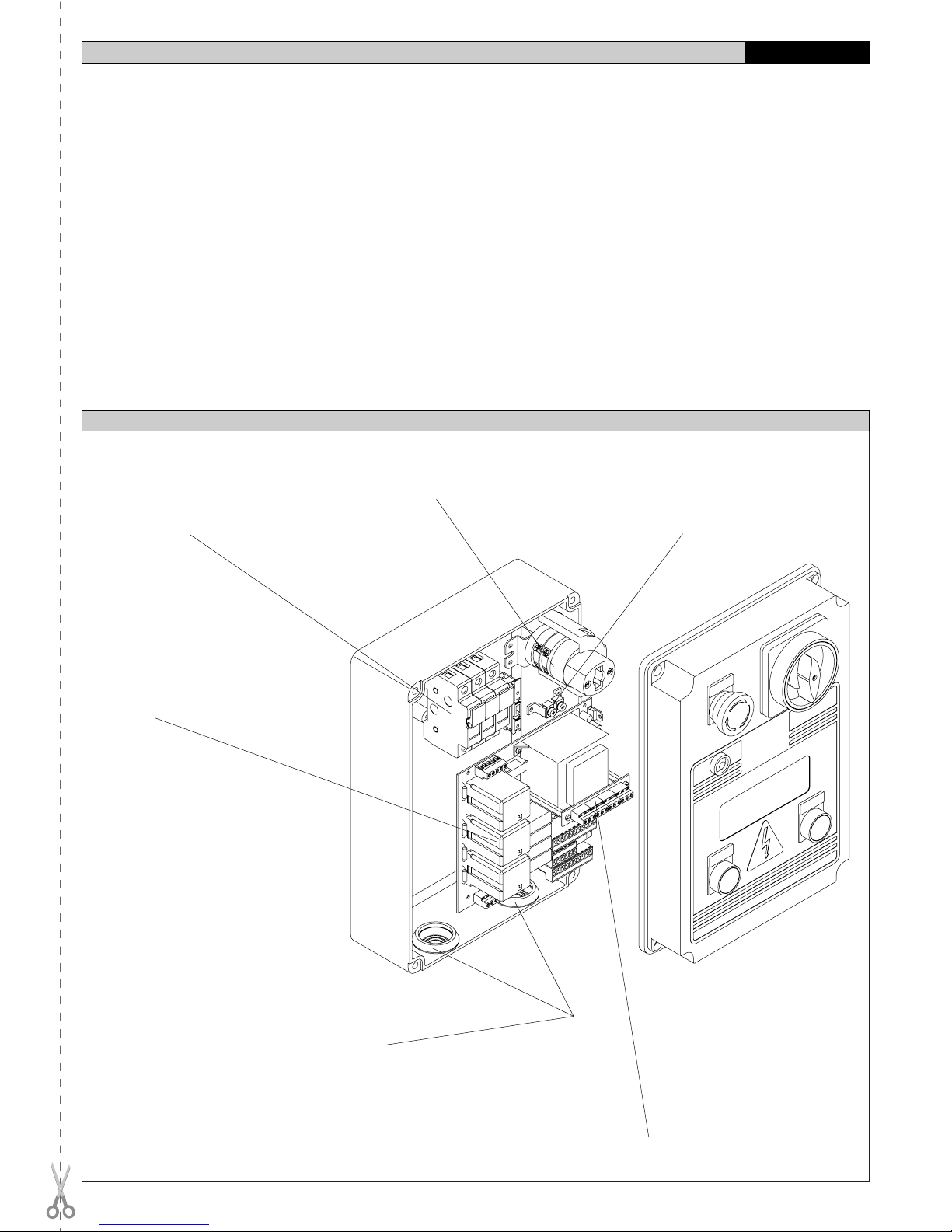
1) GENERALITÀ (Fig.1)
Il quadro, dotato di centralina a microprocessore, è adatta a controllare un
attuatore monofase o trifase per cancello scorrevole oppure sezionale.
Dispone di interruttore lucchettabile, pulsanti di apre, chiude, stop e di luce
spia di segnalazione anomalie (es.: sblocco attivo, intervento extracorsa).
Una serie di leds consente la verifica o l’individuazione di anomalie di
funzionamentodellacentralinastessaodeidispositivicollegati.Lacentralina
è dotata di Dip-switch e Trimmer che ne consentono la configurazione e la
taratura. Autodiagnosi: la centralina consente di effettuare il controllo dei
relè di marcia e dei dispositivi di sicurezza (fotocellule, costa sensibile,
ecc.), prima di eseguire ogni manovra.
2) SICUREZZA GENERALE
ATTENZIONE! Una installazione errata o un uso improprio del prodot-
to, può creare danni a persone, animali o cose.
• Leggete attentamente l’opuscolo ”Avvertenze” ed il ”Libretto istruzio-
ni” che accompagnano questo prodotto, in quanto forniscono importanti
indicazioni riguardanti la sicurezza, l’installazione, l’uso e la manuten-
zione.
• Smaltire i materiali di imballo (plastica, cartone, polistirolo, ecc.) secon-
do quanto previsto dalle norme vigenti. Non lasciare buste di nylon e
polistirolo a portata dei bambini.
• Conservare le istruzioni per allegarle al fascicolo tecnico e per consul-
tazioni future.
• Questo prodotto è stato progettato e costruito esclusivamente per
l’utilizzo indicato in questa documentazione. Usi non indicati in questa
documentazione potrebbero essere fonte di danni al prodotto e fonte di
pericolo.
• La Ditta declina qualsiasi responsabilità derivante dall’uso improprio o
diverso da quello per cui è destinato ed indicato nella presente docu-
mentazione.
• Non installare il prodotto in atmosfera esplosiva.
• La Ditta declina qualsiasi responsabilità dall’inosservanza della Buona
Tecnica nella costruzione delle chiusure (porte, cancelli, ecc.), nonché
dalle deformazioni che potrebbero verificarsi durante l’uso.
• L’installazione deve essere in accordo con quanto previsto dalle Direttive
Europee: 89/336/CEE, 73/23/CEE, 98/37/CEE e loro modifiche succes-
sive.
• Togliere l’alimentazione elettrica, prima di qualsiasi intervento sull’im-
pianto. Scollegare anche eventuali batterie tampone se presenti.
• Prevedere sulla rete di alimentazione dell’automazione, un interruttore
o un magnetotermico onnipolare con distanza di apertura dei contatti
uguale o superiore a 3mm.
• Verificare che a monte della rete di alimentazione, vi sia un interruttore
differenziale con soglia da 0.03A.
• Verificare se l’impianto di terra è realizzato correttamente: collegare
tutte le parti metalliche della chiusura (porte, cancelli, ecc.) e tutti i
componenti dell’impianto provvisti di morsetto di terra.
• La Ditta declina ogni responsabilità ai fini della sicurezza e del buon
funzionamento dell’automazione se vengono impiegati componenti di
altri produttori.
• Usare esclusivamente parti originali per qualsiasi manutenzione o
riparazione.
• Non eseguire alcuna modifica ai componenti dell’automazione se non
espressamente autorizzata dalla Ditta.
• Istruire l’utilizzatore dell’impianto per quanto riguarda i sistemi di coman-
do applicati e l’esecuzione dell’apertura manuale in caso di emergenza.
• Non permettere a persone e bambini di sostare nell’area d’azione
dell’automazione.
• Non lasciare radiocomandi o altri dispositivi di comando alla portata dei
bambini onde evitare azionamenti involontari dell’automazione.
• L’utilizzatore deve evitare qualsiasi tentativo di intervento o riparazione
dell’automazione e rivolgersi solo a personale qualificato.
• Tutto quello che non è espressamente previsto in queste istruzioni, non
è permesso.
3) DATI TECNICI
Alimentazione (*): ................................ trifase 400Vac: monofase 230Vac
Corrente uscita motore: ................................................................... 2A: 4A
Corrente commutaz.motori:........................................................... 8A: 12A
Isolamento rete - bassa tensione: ................................ > 2MOhm 500Vdc
Rigidità dielettrica rete/bt: ........................................................ 3750Vac 1'
Potenza massima motore: .................................................... 750W: 375W
Alimentazione accessori: ................................... 24Vac/0.5A: 24Vac/0.5A
Spia cancello aperto: ...................................................... 24V/3W: 24V/3W
Lampeggiatore:....................................................... 230V/40W: 230V/40W
Dimensioni: .................................................................................. vedi fig.1
(*)(altre tensioni a richiesta)
4) COLLEGAMENTI (Fig.3)
AVVERTENZE - Nelle operazioni di cablaggio ed installazione riferirsi alle
norme vigenti e comunque ai principi di buona tecnica.
I conduttori alimentati con tensioni diverse, devono essere fisicamente
separati, oppure devono essere adeguatamente isolati con isolamento
supplementare di almeno 1mm.
I conduttori devono essere vincolati da un fissaggio supplementare in
prossimità dei morsetti, per esempio mediante fascette.
ATTENZIONE! Per il collegamento alla rete, utilizzare cavo multipolare
di sezione minima 3x1.5mm2e del tipo previsto dalle normative
vigenti. A titolo di esempio, se il cavo è all’esterno (all’aperto), deve
essere almeno pari a H07RN-F mentre, se all’interno (in canaletta),
deve essere almeno pari a H05 VV-F con sezione 3x1.5mm2.
N.B.: Prima di collegare la centralina alla rete, controllare che il morsetto
JP5 (cambio tensione), sia predisposto per la giusta tensione di lavoro.
La scheda viene fornita con una serie di morsetti ponticellati. I ponti
riguardano i morsetti: 26-29, 26-30, 26-31, 26-35. Se questi morsetti non
vengano utilizzati, lasciarli ponticellati. Nella morsettiera ausiliaria SSBB1,
sono ponticellati i morsetti 6-7, 8-9, 10-11. Nel caso questi morsetti non
vengano utilizzati, lasciarli ponticellati.
QUADRO
Importante: L’alimentazione del quadro, va collegata ai morsetti del
sezionatore “S”.
S - TRIFASE
R-S-T-N ...............................................Trifase 400V ±10% 50Hz + Neutro.
ATTENZIONE! (cambio tensione JP5/39-40).
S - MONOFASE
R-N ............................................................... Monofase 230V ±10% 50Hz.
ATTENZIONE! (cambio tensione JP5/40-41).
CENTRALINA
JP1 - TRIFASE
1-2-3-4 Alimentazione trifase+neutro 400V.
(1 Neutro, 2-3-4 fase)(N.B.: ponte di JP5 tra 39-40).
5-6-7 Collegamento motore trifase.
8-9 Uscita 230Vac per luce lampeggiante.
JP1 MONOFASE
1-2 Alimentazione monofase 230V.
(1 Neutro, 2 fase) (N.B.: ponte di JP5 tra 40-41).
5-6-7 Collegamento motore monofase (5-7 marcia motore e condensa-
tore, 6 comune).
8-9 Uscita 230Vac per luce lampeggiante.
JP2
10-11 Uscita 24Vac (3W) per luce spia di segnalazione sblocco motore
e/o porta pedonale. La spia si accende a motore sbloccato
(manovra manuale) o a porta pedonale aperta.
11-12 Alimentazione accessori 24Vac e ricevitori dispositivi di sicurez-
za non sottoposti a verifica.
12-13 Alimentazione 24VTx solo per trasmettitori dispositivi di sicurez-
za sottoposti a verifica.
14 Ingresso LOOP1 dell’anello di verifica sicurezze (vedere fig.5).
15 Ingresso LOOP2 dell’anello di verifica sicurezze (vedere fig.5).
16-17 Uscita secondo canale radio scheda ricevente bicanale (n.o.).
18-19 Ingresso antenna scheda radioricevente (18 segnale, 19 calza).
JP7
20-21-22
23-24-25 Ingressi per il collegamento dei dispositivi di sicurezza da verifi-
care (vedere fig.5).