12
- ARIES/ARIES-P - Ver. 04
D811184A_04
INSTALLATION MANUAL
ENGLISH
Thank you for buying this product, our company is sure that you will be more
than satisfied with the product’s performance. The product is supplied with
a“WARNINGS”leaflet and an “INSTRUCTION MANUAL”.
These should both be read carefully as they provide important information
about safety, installation, operation and maintenance.
This product complies with the recognised technical standards and safety
regulations. We declare that this product is in conformity with the following
European Directives: 89/336/EEC and 73/23/EEC (and subsequent
amendments).
1) GENERAL OUTLINE
The ARIES control unit has been designed for swing gates. It can be used
for one or two gate controllers.
The control unit mod. ARIES P can also be used to perform opening of a
single actuator while keeping the other one closed (pedestrian access).
2) GENERAL SAFETY
WARNING! An incorrect installation or improper use of the product
can cause damage to persons, animals or things.
•The “Warnings”leaflet and “Instruction booklet”supplied with this
product should be read carefully as they provide important information
about safety, installation, use and maintenance.
•Scrap packing materials (plastic, cardboard, polystyrene etc) according
to the provisions set out by current standards. Keep nylon or polystyrene
bags out of children’s reach.
•Keep the instructions together with the technical brochure for future
reference.
•This product was exclusively designed and manufactured for the use
specified in the present documentation. Any other use not specified in
this documentation could damage the product and be dangerous.
•The Company declines all responsibility for any consequences resulting
from improper use of the product, or use which is different from that
expected and specified in the present documentation.
•Do not install the product in explosive atmosphere.
•The Company declines all responsibility for any consequences resulting
from failure to observe Good Technical Practice when constructing
closing structures (door, gates etc.), as well as from any deformation
which might occur during use.
•The installation must comply with the provisions set out by the following
European Directives: 89/336/EEC, 73/23/EEC, 98/37/ECC and
subsequent amendments.
•Disconnect the electrical power supply before carrying out any work on
the installation. Also disconnect any buffer batteries, if fitted.
•Fit an omnipolar or magnetothermal switch on the mains power supply,
having a contact opening distance equal to or greater than 3mm.
•Check that a differential switch with a 0.03A threshold is fitted just
before the power supply mains.
•Check that earthing is carried out correctly: connect all metal parts for
closure (doors, gates etc.) and all system components provided with an
earth terminal.
•The Company declines all responsibility with respect to the automation
safety and correct operation when other manufacturers’components
are used.
•Only use original parts for any maintenance or repair operation.
•Do not modify the automation components, unless explicitly authorised
by the company.
•Instruct the product user about the control systems provided and the
manual opening operation in case of emergency.
•Do not allow persons or children to remain in the automation
operation area.
•Keep radio control or other control devices out of children’s reach, in
order to avoid unintentional automation activation.
•The user must avoid any attempt to carry out work or repair on the
automation system, and always request the assistance of qualified
personnel.
•Anything which is not expressly provided for in the present instructions,
is not allowed.
3) TECHNICAL SPECIFICATIONS
Power supply:...............................................................230V ±10% 50Hz
Absorption on empty:.................................................................0.5A max
Output power for accessories:..........................................24V~ 6VA max
Max relay current:................................................................................8A
Max power of motors:...............................................................300 W x 2
Torque limiter:.................................................Self-transformer with 4 pos
Limit switch:................................................................Adjustable run time
Panel dimensions:.........................................................................See fig.1
Cabinet protection:............................................................................IP55
Working temperature:...............................................................-20 +55°C
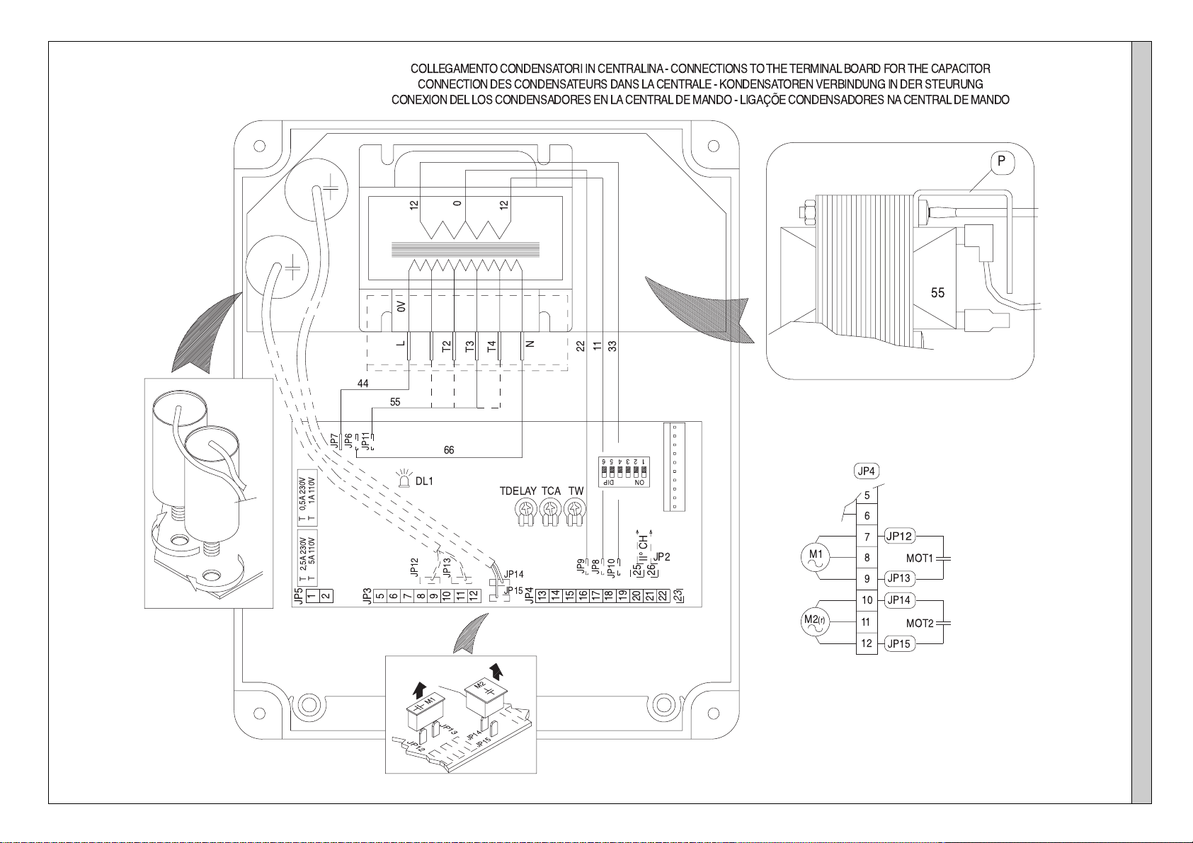
4) TERMINAL BOARD CONNECTIONS (Fig.2)
CAUTION: Keep the low voltage connections completely
separated from the power supply connections.
Fig.3 shows the fixing and connection method of the drive condensers
whenever they are not fitted to the motor.
JP5
1-2 Single-phase power supply 230V ±10%, 50 Hz (1=L/2=N).
For connection to the mains use a multiple-pole cable with a minimum
cross section of 3x1.5mm2of the type indicated in the above-mentioned
standard (by way of example, if the cable is not shielded it must be at least
equivalent to H07 RN-F while, if shielded, it must be at least equivalent to
H05 VV-F with a cross section of 3x1.5mm2).
JP3
3-4 (mod.ARIES-P) 230V 40W max. blinker connection.
5-6 (mod.ARIES) 230V 40W max. blinker connection.
7-8-9 Motor M1 connection - 8 common, 7-9 start.
10-11-12 Motor M2(r) connection - 11 common, 10-12 start.
JP4
13-14 Open-close button and key switch (N.O.).
13-15 Stop button (N.C.). If unused, leave bridged.
13-16 Photocell or pneumatic edge input (N.C.). If unused, leave bridged.
17-18 24V 3W max. gate open warning light.
18-19 24V~ 0.25A max. (6VA) output (for supplying photocell or other
device).
20-21 Antenna input for radio-receiver board (20 signal - 21 braid).
22 Common terminal (equivalent to terminal 13).
23 Terminal for pedestrian control. It moves the leaf of motor M2 connected
to terminal 10-11-12. This terminal is available only in ARIES-P control unit.
JP2
25-26 2nd radio channel output of the double-channel receiver board
(terminals not fitted on ARIES but fitted on ARIES-P) contact N.O.
JP1 Radio-receiver board connector 1-2 channels.
5) FUNCTIONS
DL1: Power-on Led
It is switched on when the board is electrically powered.
START: four-step logic: (DIP5 OFF)
gate closed:..................................................................................it opens
during opening:............................................... it stops and activates TCA
gate open:................................................................................... it closes
during closing:.................................... it stops and does not activate TCA
after stop:.........................................................................it starts opening
START: two-step logic: (DIP5 ON)
gate closed:..................................................................................it opens
during opening:................................it stops and activats TCA (if activated)
gate open:....................................................................................it closes
during closing:..............................................................................it opens
after stop:.....................................................................................it opens
STOP: In all cases: it stops the gate until a new start command is given.
PHOT: Functions can be set with DIP-SWITCH.
Activated during closing if DIP3-ON.
Activated during opening and closing if DIP3-OFF.
SCA: Gate open indicating light.
with gate closed:...................................................................................off
when gate is opening:...........................................................................on
with gate open:.......................................................................................on
when gate is closing:.....................................................................flashing
6) DIP-SWITCH SELECTION
DIP1 Rapid closing
ON: When the position of the gate photocells is exceeded, during both
opening and closing, the gate automatically starts to close even if TCA is
activated. We recommend setting DIP3 to ON (photocells only activated
during closing).
OFF: Function not activated.
DIP2 Blocks impulses
ON: During opening, START commands are not accepted.
OFF: During opening, START commands are accepted.
DIP3 Photocells
ON: Photocells only activated during closing.
OFF: Photocells activated during opening and closing.


 User manual")